2014 MITSUBISHI OUTLANDER weight
[x] Cancel search: weightPage 197 of 451

Rear-view camera (if so equipped)
Features and controls 5-119
5
Reference lines and upper surface of the rear bumper (A) are displayed on the screen. Red line (B) indicate
s approximately 20
inches (50 cm) behind the rear bumper. Two Green lines (C) indicate approxi- mately 8 inches (20 cm) outside of the vehicle body. Short transverse lines (1 to 3) indicate dis- tance from the rear bumper.
Reference lines on the screen
1: Approximately at the rear edge of the
rear bumper
2: Approximately 39 inches (100 cm) 3: Approximately 79 inches (200 cm)
CAUTION The rear-view camera uses a wide-angle lens. As a result, imag
es and distances shown
on the screen are not exact. Actual distance may
be different from dis-
tance indica
ted by the lines on the screen,
depending on the loading condition of the vehicle and road
surface condition.
The reference lines for
distance and vehicle
width are based on a level, flat road surface. In the following cases, objects shown on the screen will appear to be farther off than theyactually are.• When the rear of the vehicle is weigheddown with the weight of passengers and luggage in the ve
hicle. (Case 1)
• When there is an upward slope at the back. (Case2)
Case 1 A- Actual objects B- Objects shown on the screen
CAUTION The reference lines for distance and vehicle width are intended to i
ndicate the distance to
a flat object such as a level, flat road surface. They may not indica
te correct distance
depending on the shape of an obstacle.For example, when ther
e is an object behind
the vehicle that has uppe
r sections projecting
in the direction of the vehicle, the referencelines on the screen will
indicate that point A
is the farthest point a
nd point B is the closest
point to the vehicle. In
reality, point A and B
are actually the same distance from the vehi- cle, and point C is fa
rther off than point A
and B.Case 2 A- Actual objects B- Objects shown on the screen
BK0200500US.book 119 ページ 2013年2月12日 火曜日 午前9時46分
Page 299 of 451
Assist grips
Features and controls 5-221
5
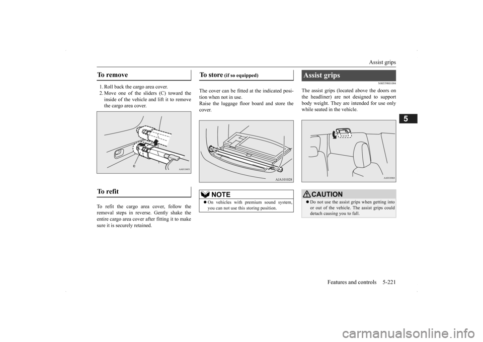
1. Roll back the cargo area cover. 2. Move one of the sliders (C) toward the inside of the vehicle and lift it to remove the cargo area cover.
To refit the cargo area cover, follow the removal steps in reverse. Gently shake theentire cargo area cover after fitting it to make sure it is securely retained.
The cover can be fitted
at the indicated posi-
tion when not in use.Raise the luggage floor board and store the cover.
N00559001084
The assist grips (located above the doors onthe headliner) are not designed to support body weight. They are intended for use onlywhile seated in the vehicle.
To remove To refit
To store
(if so equipped)
NOTE
On vehicles with premium sound system, you can not use this storing position.
Assist grips
CAUTION Do not use the assist grips when getting into or out of the vehicle.
The assist grips could
detach causing you to fall.
BK0200500US.book 221 ページ 2013年2月12日 火曜日 午前9時46分
Page 306 of 451
Parking 6-6 Driving safety
6
N00629601330
When parking on a hill, set the parking brake, and turn the front wheels toward the curb on a downhill, or away from
the curb on an uphill.
If necessary, apply chocks to the wheels. Be sure that the parki
ng brake is firmly set
when parked and that the selector lever is in the “P” (PARK) position. When parking on a hill, it
is important to set
the parking brake before moving the selector lever to the “P” (PARK) position. This pre- vents loading the parking brake against thetransaxle. When this ha
ppens, it is difficult to
move the selector lever out of the “P” (PARK) position. Never leave the engine running while you take a short nap or rest. Also, never leave the engine running in a closed or poorly venti- lated place.
Your front bumper can be damaged if you scrape it over curbs or parking stop blocks.Be careful when traveling up or down steep slopes where your bumper can scrape the road. Always remove the key from the ignition switch and lock all doors and the liftgate when leaving the
vehicle unattended.
Always try to park your vehicle in a well lit area.
Move effort could be required to turn the steering wheel.Refer to “Electric power steering system (EPS)” on page 5-89.
N00629900352
It is very important to know how much weight your vehicle can carry. This weight iscalled the vehicle ca
pacity weight and
includes the weight of
all occupants, cargo
(including the roof load), non-factory-installed options, and the tongue weight of the trailer, if any, being towed. The tire and loading information placard located on thedriver’s door sill of
your vehicle will show
how much weight it may properly carry. It is important to familiarize yourself with the following terms before
loading your vehicle:
Parking Parking on a hill Parking with the engine run- ning
WA R N I N G Leaving the engine ru
nning risks injury or
death from accidentally moving the selec-tor lever or the accumulation of toxicexhaust fumes in the passenger compart- ment.
Where you park
WA R N I N G Do not park your vehicle in areas where combustible materials
such as dry grass or
leaves can come in contact with a hotexhaust, since a fire could occur.
When leaving the vehicle
Do not keep the steering wheel fully turned for a long time Loading information
WA R N I N G Never overload your ve
hicle. Overloading
can damage your vehicle, adversely affectvehicle performance, including handling and braking, cause tire failure, and result in an accident.
BK0200500US.book 6 ページ 2013年2月12日 火曜日 午前9時46分
Page 307 of 451
Loading information Driving safety 6-7
6
Vehicle maximum load on the tire: load on an individual tire that is determined bydistributing to each axle its share of the maximum loaded vehicle weight and dividing by two. Vehicle normal load on the tire: load on an individual tire that is determined by dis- tributing to each axle its share of the curbweight, accessory weight, and normal occupant weight and dividing by two. Maximum loaded vehicle weight: the sum of - (a) Curb weight;(b) Accessory weight; (c) Vehicle capacity weight; and (d) Production options weight. Curb weight: the weight of a motor vehi- cle with standard e
quipment including the
maximum capacity of fuel, oil, and cool-ant. Accessory weight: the combined weight (in excess of those
standard items which
may be replaced) of automatic transmis- sion, power steering, power brakes, power windows, power seats, radio, and heater,to the extent that these items are available as factory- installed equipment (whether installed or not). Vehicle capacity weight: the rated cargo and luggage load plus 150 lbs (68 kg) * times the vehicle’s
designated seating
capacity.
Production options weight: the combined weight of those installed regular produc-tion options weighing over 5 lbs (2.3 kg) in excess of those standard items which they replace, not prev
iously considered in
curb weight or accessory weight, includ- ing heavy duty brakes,
ride levelers, roof
rack, heavy duty battery, and special trim. Normal occupant weight: 150 lbs (68 kg) * times the number of
specified occupants
(3 in the case of your vehicle) Occupant distribution:
Occupant distribu-
tion within the passenger compartment (Inyour vehicle the distribution is 2 in front, 1 in second row seat)
N00630101407
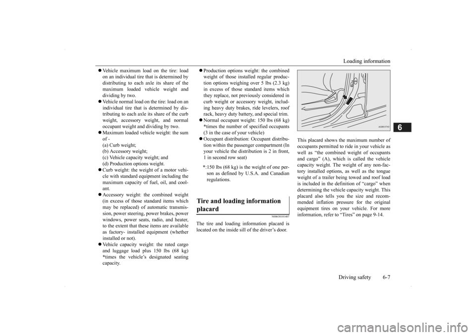
The tire and loading information placard is located on the inside sill of the driver’s door.
This placard shows the maximum number of occupants permitted to
ride in your vehicle as
well as “the combined
weight of occupants
and cargo” (A), which
is called the vehicle
capacity weight. The weight of any non-fac-tory installed options, as well as the tongue weight of a trailer being towed and roof load is included in the defi
nition of “cargo” when
determining the vehicle
capacity weight. This
placard also tells you the size and recom- mended inflation pressure for the originalequipment tires on your vehicle. For more information, refer to
“Tires” on page 9-14.
* :150 lbs (68 kg) is th
e weight of one per-
son as defined by U.S.A. and Canadian regulations.
Tire and loading information placard
BK0200500US.book 7 ページ 2013年2月12日 火曜日 午前9時46分
Page 308 of 451
Loading information 6-8 Driving safety
6
Ty p e 1 Ty p e 2
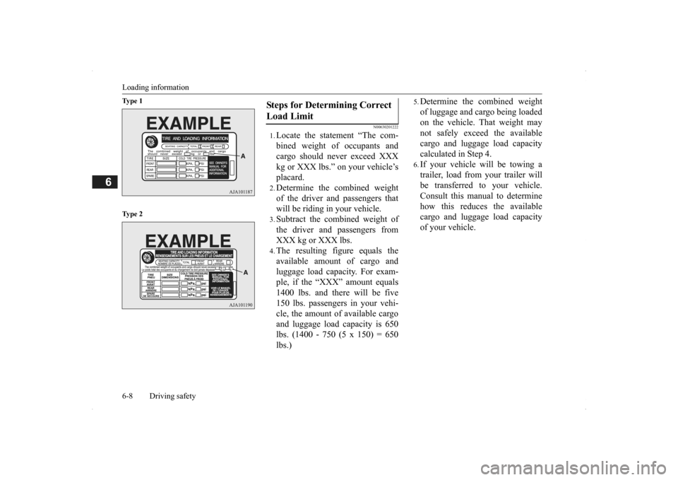
N00630201222
1.Locate the statement “The com- bined weight of occupants and cargo should never exceed XXX kg or XXX lbs.” on your vehicle’splacard.2.Determine the combined weightof the driver and passengers thatwill be riding in your vehicle.3.Subtract the combined weight ofthe driver and passengers fromXXX kg or XXX lbs.4.The resulting figure equals theavailable amount of cargo andluggage load capacity. For exam- ple, if the “XXX” amount equals 1400 lbs. and there will be five150 lbs. passengers in your vehi- cle, the amount of available cargo and luggage load
capacity is 650
lbs. (1400 - 750 (5 x 150) = 650lbs.)
5.Determine the combined weightof luggage and cargo being loaded on the vehicle. That weight may not safely exceed the availablecargo and luggage load capacity calculated in Step 4.6.If your vehicle will be towing a trailer, load from your trailer will be transferred to your vehicle. Consult this manual to determinehow this reduces the available cargo and luggage load capacity of your vehicle.
Steps for Determining Correct Load Limit
BK0200500US.book 8 ページ 2013年2月12日 火曜日 午前9時46分
Page 309 of 451
Loading information Driving safety 6-9
6
NOTE
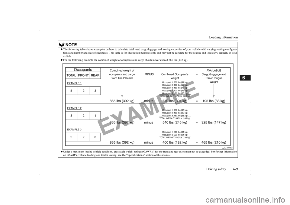
The following table shows examples on how to
calculate tota
l load, cargo/luggage and towing capa
cities of your vehicle with var
ying seating configura-
tions and number and size of occ
upants. This table is for illu
stration purposes only and may not
be accurate for the seating an
d load carry capacity of your
vehicle. For the following example the combined weight of oc
cupants and cargo should ne
ver exceed 865 lbs (392 kg).
Under a maximum loaded vehicle c
ondition, gross axle weight ratings (GAWR’s) for
the front and rear axles must not be exceeded.
For further information
on GAWR’s, vehicle loading and tr
ailer towing, see the “Specifica
tions” section of this manual.
BK0200500US.book 9 ページ 2013年2月12日 火曜日 午前9時46分
Page 310 of 451
Cargo loads 6-10 Driving safety
6
N00629700435 N00630301092
To determine the cargo load capacity for your vehicle, subtract the
weight of all vehicle
occupants from the vehi
cle capacity weight.
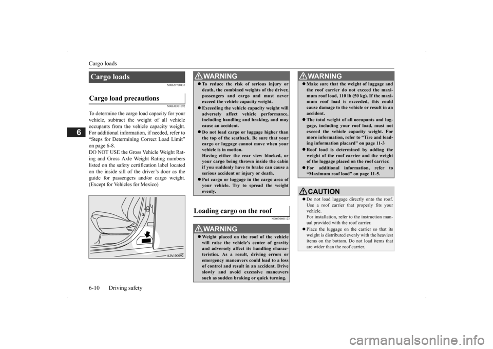
For additional information, if needed, refer to “Steps for Determining Correct Load Limit” on page 6-8. DO NOT USE the Gross Vehicle Weight Rat- ing and Gross Axle Weight Rating numberslisted on the safety certification label located on the inside sill of the driver’s door as the guide for passengers and/or cargo weight.(Except for Vehicles for Mexico)
N00630401123
Cargo loads Cargo load precautions
WA R N I N G To reduce the risk of serious injury or death, the combined weights of the driver,passengers and cargo and must neverexceed the vehicle capacity weight. Exceeding the vehicle capacity weight will adversely affect ve
hicle performance,
including handling and braking, and may cause an accident. Do not load cargo or luggage higher than the top of the seatback. Be sure that yourcargo or luggage cann
ot move when your
vehicle is in motion. Having either the re
ar view blocked, or
your cargo being thrown
inside the cabin
if you suddenly have to brake can cause a serious accident or
injury or death.
Put cargo or luggage in the cargo area of your vehicle. Try to spread the weightevenly.
Loading cargo on the roof
WA R N I N G Weight placed on the
roof of the vehicle
will raise the vehicle’
s center of gravity
and adversely affect
its handling charac-
teristics. As a result, driving errors oremergency maneuvers could lead to a loss of control and result in an accident. Drive slowly and avoid excessive maneuverssuch as sudden brak
ing or quick turning.
Make sure that the
weight of luggage and
the roof carrier do not exceed the maxi-mum roof load, 110 lb (50 kg). If the maxi-mum roof load is ex
ceeded, this could
cause damage to the ve
hicle or result in an
accident. The total weight of all occupants and lug- gage, including your r
oof load, must not
exceed the vehicle capacity weight. For more information, refer to “Tire and load- ing information placard” on page 11-3 Roof load is determined by adding the weight of the roof
carrier and the weight
of the luggage placed
on the roof carrier.
For additional information, refer to “Maximum roof load” on page 11-5.CAUTION Do not load luggage directly onto the roof. Use a roof carrier that properly fits your vehicle. For installation, refer to the instruction man-ual provided with the roof carrier. Place the luggage on the carrier so that its weight is distri
buted evenly with the heaviest
items on the bottom. Do not load items that are wider than the roof carrier.WA R N I N G
BK0200500US.book 10 ページ 2013年2月12日 火曜日 午前9時46分
Page 311 of 451
Trailer towing
Driving safety 6-11
6
N00630601112
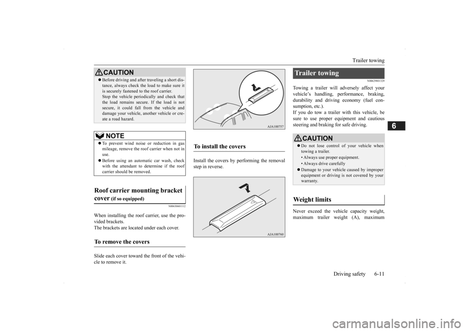
When installing the roof carrier, use the pro- vided brackets. The brackets are located under each cover. Slide each cover toward
the front of the vehi-
cle to remove it.
Install the covers by performing the removal step in reverse.
N00629801329
Towing a trailer will adversely affect your vehicle’s handling, performance, braking, durability and driving economy (fuel con-sumption, etc.). If you do tow a trailer
with this vehicle, be
sure to use proper e
quipment and cautious
steering and braking for safe driving. Never exceed the vehi
cle capacity weight,
maximum trailer weight (A), maximum
Before driving and after traveling a short dis- tance, always check the load to make sure itis securely fastened to the roof carrier.Stop the vehicle periodi
cally and check that
the load remains secure. If the load is not secure, it could fall from the vehicle anddamage your vehicle,
another vehicle or cre-
ate a road hazard.NOTE
To prevent wind noise or reduction in gas mileage, remove the roof carrier when not in use. Before using an automatic car wash, check with the attendant to determine if the roofcarrier should be removed.
Roof carrier mounting bracket cover
(if so equipped)
To remove the covers
CAUTION
To install the covers
Trailer towing
CAUTION Do not lose control of your vehicle when towing a trailer.• Always use proper equipment.• Always drive carefully Damage to your vehicle caused by improper equipment or driving is not covered by your warranty.
Weight limits
BK0200500US.book 11 ページ 2013年2月12日 火曜日 午前9時46分