2014 MITSUBISHI OUTLANDER power steering
[x] Cancel search: power steeringPage 167 of 451

Electric power steering system (EPS)
Features and controls 5-89
5
N00529201090
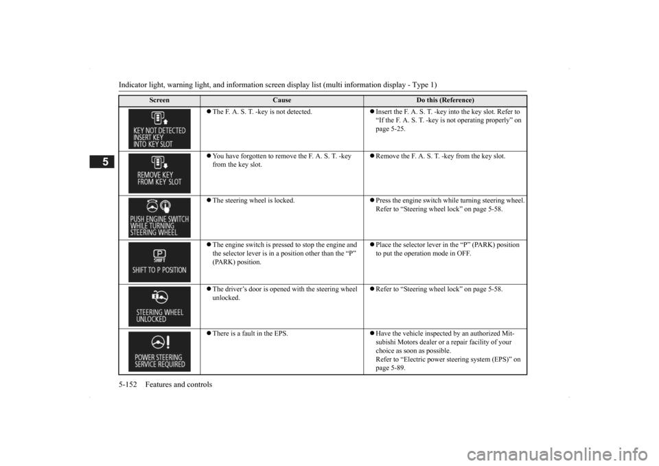
After driving on snow or icy roads, remove any snow and ice which may have be leftaround the wheels. On vehicles that have an anti-lock braking syst
em, be careful not to
damage the wheel spee
d sensors (A) or the
cables located at each wheel.
N00568401084
The power steering system operates while the engine is running. It helps reduce the effort needed to turn the steering wheel.The power steering sy
stem has mechanical
steering capability in case the power assist is lost. If the power assist is lost for some rea-son, you will still be able to steer your vehi- cle, but you will notice it takes much more effort to steer. If this happens, have your vehi- cle inspected at an authorized Mitsubishi Motors dealer or a repair facility of yourchoice.
Warning lamp Warning display
NOTE
The anti-lock braking
system warning light
and brake warning light illuminate at thesame time and the wa
rning displays appear
alternately on the information screen in the multi-information display.
After driving on icy roads Front Rear
Electric power steering sys- tem (EPS)
WA R N I N G Do not stop the engine while the vehicle is moving. Stopping the engine would make the steering wheel extremely hard to turn, possibly resulting
in an ac
cident.
NOTE
During repeated full-lock turning of the steering wheel (for example, while you aremanoeuvring the vehicle into a parkingspace), a protection f
unction may be acti-
vated to prevent overheating of the power steering system. This f
unction will make the
steering wheel graduall
y harder to turn. In
this event, limit your turning of the steering wheel for a while. When the system hascooled down, the steering effort will return to normal. If you turn the steering wheel while the vehi- cle is stationary with the headlights on, the headlights may become
dim. This behavior
is not abnormal. The he
adlights will return to
their original brightness after a short while.
Electric power steering system warning display
BK0200500US.book 89 ページ 2013年2月12日 火曜日 午前9時46分
Page 230 of 451

Indicator light, warning light, and information screen display list (multi information display - Type 1) 5-152 Features and controls
5
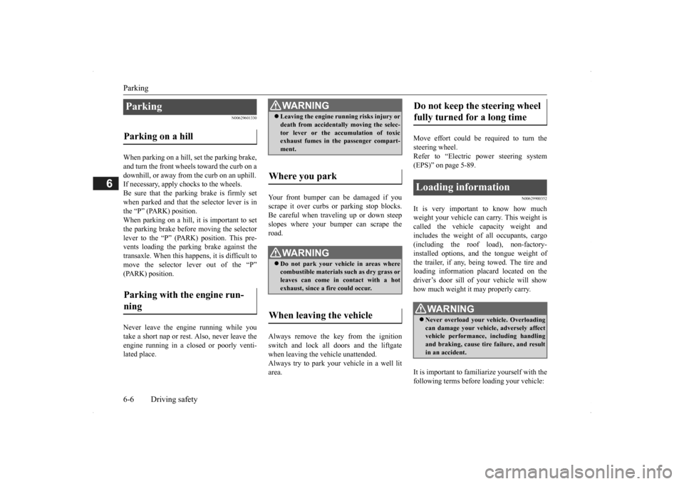
The F. A. S. T. -key is not detected.
Insert the F. A. S. T. -key
into the key slot. Refer to
“If the F. A. S. T. -key is not operating properly” on page 5-25.
You have forgotten to remove the F. A. S. T. -key from the key slot.
Remove the F. A. S. T. -key from the key slot.
The steering wheel is locked.
Press the engine switch while turning steering wheel. Refer to “Steering wheel lock” on page 5-58.
The engine switch is presse
d to stop the engine and
the selector lever is in a
position other than the “P”
(PARK) position.
Place the selector lever in the “P” (PARK) position to put the operation mode in OFF.
The driver’s door is opened with the steering wheel unlocked.
Refer to “Steering wheel lock” on page 5-58.
There is a fault in the EPS.
Have the vehicle inspected by an authorized Mit- subishi Motors dealer or
a repair facility of your
choice as soon as possible. Refer to “Electric power steering system (EPS)” on page 5-89.
Screen
Cause
Do this (Reference)
BK0200500US.book 152 ページ 2013年2月12日 火曜日 午前9時46分
Page 243 of 451

Indicator and warning light package (multi information display - Type 2)
Features and controls 5-165
5
N00519801859
Indicator and warning light package (mu
lti information display - Type 2)
1- Position indicator
P. 5-166
2- Front fog light indicator (if so
equipped)
P. 5-166
3- Turn signal indicators/hazard warning
lights
P. 5-166
4- Cruise control indicator
P. 5-92
5- Door-ajar warning light
P. 5-169
6- For details, refer to “Warning activa-
tion” on page 5-18. (if so equipped)
7- For details, refer to “Warning activa-
tion” on page 5-18. (if so equipped)
8- Electric power steering system warn-
ing light
P .5-89
9- High beam indicator
P. 5-166
10- ECO mode indicator
P .5-178
11- ECO Drive Assist
P. 5-166
12- Oil pressure warning light
P. 5-168
13- Charging system warning light
P. 5-168
14- High coolant temperature warning light
(red)
P. 5-169
15- Low coolant temperature indicator
(blue)
P. 5-166
16- Active stability control (ASC) indicator
P. 5 - 9 1
17- Active stability
control (ASC) OFF
indicator P. 5 - 9 1
18- Anti-lock braking system warning light
P. 5-87
19- Supplemental Restra
int System (SRS)
warning light
P. 4 - 3 9
20- Engine malfuncti
on indicator (“SER-
VICE ENGINE SOON” or “Check engine light”)
P. 5-167
21- Seat belt remi
nder/warning light
P. 4-22
22- The tire pressure monitoring system
warning light
P. 5 - 1 1 5
23- Brake warning light
P. 5-167
24- Multi information display
P. 5-140
BK0200500US.book 165 ページ 2013年2月12日 火曜日 午前9時46分
Page 262 of 451

Electric rear window defogger switch 5-184 Features and controls
5
N00523701413
The rear window defogger can be used when the engine is running. The indicator light (A) will come on whenyou press the electric rear window defogger switch. Electric current will flow through the heating wires on the rear window to helpclear away moisture or frost.
After about 15 to 20 minutes of operation, the system will shut off automatically.To switch the defogger OFF before 15 to 20 minutes have passed, pr
ess the switch again.
The indicator light will go out and the defog-ger will turn off. If you need the defogger for more than 15 to 20 minutes, press the switch again. This willadd 15 to 20 more minutes.
N00523801195
To honk the horn, press around the “ ” markon the steering wheel.
If the wipers become bl
ocked by ice or other
deposits on the glass, the motor may stillburn out even if the wiper switch is OFF. Ifdeposits form on the windshield, park your vehicle in a safe place, turn off the engine, and clean the glass so that the wipers canoperate smoothly. Avoid using the washer for more than 20 sec- onds at a time. Do not
operate the washer
when the washer fluid reservoir is empty or the pump may fail. During cold weather, add a recommended washer solution that will not freeze in thewasher fluid reservoir. Otherwise the washer may not work or may be damaged. Replace the wiper blades when they are worn. Use the proper size replacement blades. For further info
rmation, please con-
tact your authorized
Mitsubishi Motors
dealer.
Electric rear window defog- ger switch
NOTE
CAUTION The rear window defogge
r is not designed to
melt snow. Remove
any snow manually
before using the rear window defogger. Use the rear window de
fogger only after the
engine has started and
is running. Be sure to
turn the defogger switch off immediatelyafter the window is cl
ear to save on battery
power.
Do not place stickers
, tape, or other items
that are attached with
adhesive over the grid
wires on the rear window. When cleaning the insi
de rear window, use a
soft cloth and wipe
lightly over the grid
wires.NOTE
The rear window defogger can be turned on automatically. For further information, please contact your authorized Mitsubishi Motors dealer.On vehicles e
quipped with Mitsubishi Multi-
Communication System, screen operations can be used to ma
ke the adjustment.
Refer to the separate
owner’s manual for
details. As your vehicle is equi
pped with heated mir-
rors, mist can also be removed from the out- side rearview mirrors
when the rear window
defogger switch is pre
ssed. (Refer to “Door
mirror heater” on page 5-56.)
Horn switch
CAUTION
BK0200500US.book 184 ページ 2013年2月12日 火曜日 午前9時46分
Page 264 of 451

Bluetooth® 2.0 interface (if so equipped) 5-186 Features and controls
5
Steering control switch and microphone
P.5-186Voice recognition function
P.5-188
Useful voice commands
P.5-189
Speaker enrollment function
P.5-190
Connecting the Bluetooth
® 2.0 interface and
the Bluetooth
® device
P.5-192
Operating a music player connected via Blue- tooth
® P.5-196
How to make or receive hands-free calls
P.5-196Phonebook function
P.5-199
N00564001109
Press this button to increase the volume.
NOTE
If the ignition switch
or the operation mode
is left in ACC, the accessory power willautomatically turn off after a certain periodof time and you will no longer be able to use the Bluetooth
® 2.0 interface. The accessory
power comes on again if
the ignition switch
or the engine switch is operated. Refer to“ACC power auto-cut
out function” on page
5-18 and 5-57. The Bluetooth
® 2.0 interface cannot be used
if the Bluetooth
® device has a dead battery
or the device power is turned off. Hands-free calls
will not be possible if your
phone does not have
service available.
If you place the Bluetooth
® device in the
vehicle’s third seat or
luggage compartment,
you may not be able to
use the Bluetooth
®
2.0 interface. Some Bluetooth
® devices are not compatible
with the Bluetooth
® 2.0 interface.
You can confirm the Link System software version by pressing the HANG-UP button 3times (press and hold 2 times and then press briefly) within 10 seconds.
For detail of the Bluetooth
® 2.0 interface,
refer to the following web site: [For vehicles sold in U.S.A.] You can access the MITSUBISHI MOTORSNORTH AMERICA web site. [For vehicles sold in Canada and Mexico] You can access the MITSUBISHI MOTORSweb site. Please read and agree to the “Warning about Links to the Web Sites of Other Companies”,the websites mentioned above may connect you to websites other
than the MITSUBISHI
MOTORS web site.http://www.mitsubishi-motors.com/en/prod- ucts/index.html Software updates by ce
llular phone/digital
audio device manufacturers may change/alter devi
ce connectivity.
NOTE
Steering control switch and microphone
1- Volume up button 2- Volume down button 3- SPEECH button4- PICK-UP button 5- HANG-UP button 6- MicrophoneVolume up button
BK0200500US.book 186 ページ 2013年2月12日 火曜日 午前9時46分
Page 306 of 451

Parking 6-6 Driving safety
6
N00629601330
When parking on a hill, set the parking brake, and turn the front wheels toward the curb on a downhill, or away from
the curb on an uphill.
If necessary, apply chocks to the wheels. Be sure that the parki
ng brake is firmly set
when parked and that the selector lever is in the “P” (PARK) position. When parking on a hill, it
is important to set
the parking brake before moving the selector lever to the “P” (PARK) position. This pre- vents loading the parking brake against thetransaxle. When this ha
ppens, it is difficult to
move the selector lever out of the “P” (PARK) position. Never leave the engine running while you take a short nap or rest. Also, never leave the engine running in a closed or poorly venti- lated place.
Your front bumper can be damaged if you scrape it over curbs or parking stop blocks.Be careful when traveling up or down steep slopes where your bumper can scrape the road. Always remove the key from the ignition switch and lock all doors and the liftgate when leaving the
vehicle unattended.
Always try to park your vehicle in a well lit area.
Move effort could be required to turn the steering wheel.Refer to “Electric power steering system (EPS)” on page 5-89.
N00629900352
It is very important to know how much weight your vehicle can carry. This weight iscalled the vehicle ca
pacity weight and
includes the weight of
all occupants, cargo
(including the roof load), non-factory-installed options, and the tongue weight of the trailer, if any, being towed. The tire and loading information placard located on thedriver’s door sill of
your vehicle will show
how much weight it may properly carry. It is important to familiarize yourself with the following terms before
loading your vehicle:
Parking Parking on a hill Parking with the engine run- ning
WA R N I N G Leaving the engine ru
nning risks injury or
death from accidentally moving the selec-tor lever or the accumulation of toxicexhaust fumes in the passenger compart- ment.
Where you park
WA R N I N G Do not park your vehicle in areas where combustible materials
such as dry grass or
leaves can come in contact with a hotexhaust, since a fire could occur.
When leaving the vehicle
Do not keep the steering wheel fully turned for a long time Loading information
WA R N I N G Never overload your ve
hicle. Overloading
can damage your vehicle, adversely affectvehicle performance, including handling and braking, cause tire failure, and result in an accident.
BK0200500US.book 6 ページ 2013年2月12日 火曜日 午前9時46分
Page 307 of 451

Loading information Driving safety 6-7
6
Vehicle maximum load on the tire: load on an individual tire that is determined bydistributing to each axle its share of the maximum loaded vehicle weight and dividing by two. Vehicle normal load on the tire: load on an individual tire that is determined by dis- tributing to each axle its share of the curbweight, accessory weight, and normal occupant weight and dividing by two. Maximum loaded vehicle weight: the sum of - (a) Curb weight;(b) Accessory weight; (c) Vehicle capacity weight; and (d) Production options weight. Curb weight: the weight of a motor vehi- cle with standard e
quipment including the
maximum capacity of fuel, oil, and cool-ant. Accessory weight: the combined weight (in excess of those
standard items which
may be replaced) of automatic transmis- sion, power steering, power brakes, power windows, power seats, radio, and heater,to the extent that these items are available as factory- installed equipment (whether installed or not). Vehicle capacity weight: the rated cargo and luggage load plus 150 lbs (68 kg) * times the vehicle’s
designated seating
capacity.
Production options weight: the combined weight of those installed regular produc-tion options weighing over 5 lbs (2.3 kg) in excess of those standard items which they replace, not prev
iously considered in
curb weight or accessory weight, includ- ing heavy duty brakes,
ride levelers, roof
rack, heavy duty battery, and special trim. Normal occupant weight: 150 lbs (68 kg) * times the number of
specified occupants
(3 in the case of your vehicle) Occupant distribution:
Occupant distribu-
tion within the passenger compartment (Inyour vehicle the distribution is 2 in front, 1 in second row seat)
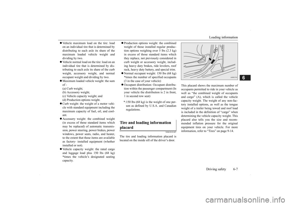
N00630101407
The tire and loading information placard is located on the inside sill of the driver’s door.
This placard shows the maximum number of occupants permitted to
ride in your vehicle as
well as “the combined
weight of occupants
and cargo” (A), which
is called the vehicle
capacity weight. The weight of any non-fac-tory installed options, as well as the tongue weight of a trailer being towed and roof load is included in the defi
nition of “cargo” when
determining the vehicle
capacity weight. This
placard also tells you the size and recom- mended inflation pressure for the originalequipment tires on your vehicle. For more information, refer to
“Tires” on page 9-14.
* :150 lbs (68 kg) is th
e weight of one per-
son as defined by U.S.A. and Canadian regulations.
Tire and loading information placard
BK0200500US.book 7 ページ 2013年2月12日 火曜日 午前9時46分
Page 315 of 451

Trailer towing
Driving safety 6-15
6
Hold the bottom of the steering wheel with one hand. Then, to move the trailer to the left, just move that hand to the left. To move thetrailer to the right, move your hand to the right. Always back up sl
owly and, if possible,
have someone guide you. When you’re turning with a trailer, make wider than normal turns to help prevent the trailer from striking shoulders, curbs, roadsigns, trees or other objects. Avoid jerky or sudde
n maneuvers. Signal
well in advance. Towing a trailer puts a
dditional burden on the
engine and transaxle,
which may cause over-
heating. Following ar
e some suggestions to
reduce overheating: When towing at high al
titudes, engine coolant
and automatic transaxle oil will overheat at a lower temperature than at normal altitudes.If you turn your engine off immediately after towing at high altitude
on steep uphill grades,
your vehicle may show
signs similar to over-
heating. To avoid this
, let the engine run
while parked (preferably on level ground) with the automatic transaxle in the “P”(PARK) position for a few minutes before turning the engine off. If the engine coolant temperature indica- tor flashes on the in
formation screen in
the multi-information display or the engine power drops suddenly, refer to “Engine overheating” on page 8-4.
If the warning display or warning display illuminates, re
fer to “Warning dis-
play” on page 5-62, 5-70.
Reduce speed and downshift before you start down a long or steep downgrade. If you don’t downshift, over using the brakes can cause reduced brake efficiency. You can tow in “D” (DRIVE) position. You may want to shift the selector lever to the 3rd or a lower position, under heavy loads or hillyconditions. Always place chocks or blocks under both the vehicle and trailer wheels when parking. Be sure that the parking brake is firmly set and that the selector lever is in the “P” (PARK)position. Avoid parki
ng on a hill with a
trailer, but if it cannot be avoided, do so only after performing the following: 1. Apply the brakes and keep them applied. 2. Have someone plac
e chocks or blocks
under both the vehicle
and trailer wheels.
Backing up Making turns
CAUTION Making sharp turns while towing a trailer could cause the
trailer to come in contact
with the vehicle. Your
vehicle could be dam-
aged. Avoid making sharp turns while tow- ing a trailer.
Overheating
Cause of overheating
Solution
Air conditioning on Turn off Highway speeds Reduce speed Going up hills Select lower gear posi-
tion
Stop-and-go city traf- fic
With the vehicle stopped, shift to the “N” (NEUTRAL) position and idle the engine at high idle.
Driving on hills Parking
BK0200500US.book 15 ページ 2013年2月12日 火曜日 午前9時46分