2014 MITSUBISHI LANCER SPORTBACK belt
[x] Cancel search: beltPage 205 of 422
Indicator light, warning light, an
d information screen display list
5-138 Features and controls
5
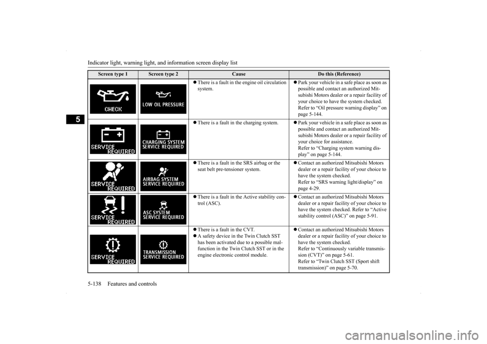
There is a fault in the engine oil circulation system.
Park your vehicle in a safe place as soon as possible and contact an authorized Mit- subishi Motors dealer or a repair facility of your choice to have the system checked. Refer to “Oil pressure warning display” on page 5-144.
There is a fault in the charging system.
Park your vehicle in a safe place as soon as possible and contact an authorized Mit- subishi Motors dealer or a repair facility of your choice for assistance.Refer to “Charging system warning dis- play” on page 5-144.
There is a fault in the SRS airbag or the seat belt pre-tensioner system.
Contact an authorized Mitsubishi Motors dealer or a repair facility of your choice to have the system checked. Refer to “SRS warning light/display” on page 4-29.
There is a fault in the Active stability con- trol (ASC).
Contact an authorized Mitsubishi Motors dealer or a repair facility of your choice to have the system checked. Refer to “Active stability control (ASC)” on page 5-91.
There is a fault in the CVT. A safety device in the Twin Clutch SST has been activated due to a possible mal- function in the Twin Clutch SST or in the engine electronic control module.
Contact an authorized Mitsubishi Motors dealer or a repair facility of your choice to have the system checked. Refer to “Continuously variable transmis-sion (CVT)” on page 5-61. Refer to “Twin Clutch SST (Sport shift transmission)” on page 5-70.
Screen type 1
Screen type 2
Cause
Do this (Reference)
BK0200700US.book
138 ページ 2013年2月15日 金曜日 午後12時17分
Page 248 of 422
USB input terminal (if so equipped)
Features and controls 5-181
5
5. To remove the USB connector cable, turn the ignition switch to the “LOCK” posi- tion first and perform the installation steps in reverse.
N00566900059
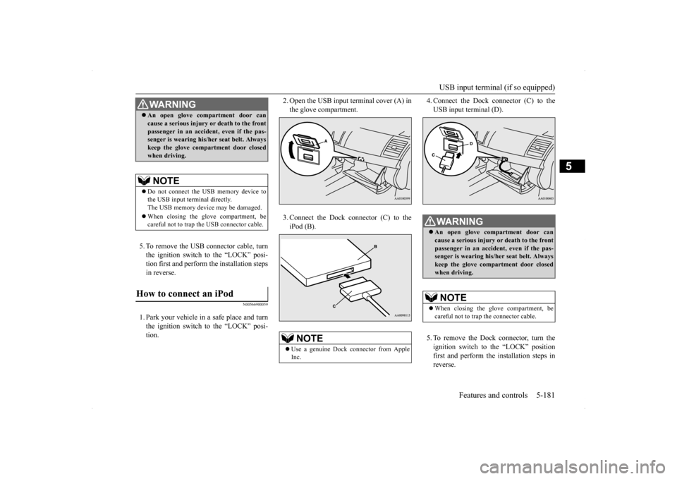
1. Park your vehicle in a safe place and turnthe ignition switch to the “LOCK” posi- tion.
2. Open the USB input terminal cover (A) in the glove compartment. 3. Connect the Dock connector (C) to the iPod (B).
4. Connect the Dock connector (C) to the USB input terminal (D). 5. To remove the Dock connector, turn the ignition switch to the “LOCK” positionfirst and perform the installation steps in reverse.
WA R N I N G An open glove compartment door can cause a serious injury or death to the front passenger in an accident, even if the pas- senger is wearing his/her seat belt. Always keep the glove compartment door closedwhen driving.NOTE
Do not connect the USB memory device to the USB input terminal directly.The USB memory device may be damaged. When closing the glove compartment, be careful not to trap the USB connector cable.
How to connect an iPod
NOTE
Use a genuine Dock connector from Apple Inc.
WA R N I N G An open glove compartment door can cause a serious injury or death to the front passenger in an accident, even if the pas-senger is wearing his/her seat belt. Always keep the glove compartment door closed when driving.NOTE
When closing the glove compartment, be careful not to trap the connector cable.
BK0200700US.book
181 ページ 2013年2月15日 金曜日 午後12時17分
Page 254 of 422
Storage spaces
Features and controls 5-187
5
N00526400498
N00551500246
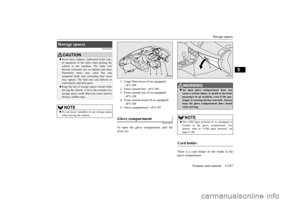
To open the glove compartment, pull the lever (A).
There is a card holder on the inside of the glove compartment.
Storage spaces
CAUTION Never leave lighters, carbonated drink cans, or spectacles in the cabin when parking the vehicle in hot sunshine. The cabin will become extremely hot, so lighters and otherflammable items may catch fire and unopened drink cans (including beer cans) may rupture. The heat may also deform orcrack plastic spectacle parts. Keep the lids of stor
age spaces closed while
driving the vehicle. A lid or the contents of a storage space could otherwise cause injuries during a sudden stop.NOTE
Do not leave valuables in any storage space when leaving the vehicle.
1- Cargo floor boxes (if so equipped)
P.5-189
2- Floor console box
P.5-188
3- Front console tray (if so equipped)
P.5-188
4- Front console boxes (if so equipped)
P.5-188
5- Glove compartment
P.5-187
Glove compartment
WA R N I N GAn open glove compartment door can cause a serious injury or death to the front passenger in an accident, even if the pas- senger is wearing his/her seat belt. Alwayskeep the glove compartment door closed when driving. NOTE
The USB input terminal (if so equipped) is located in the glove compartment. For details, refer to “USB input terminal” on page 5-180.
Card holder
BK0200700US.book
187 ページ 2013年2月15日 金曜日 午後12時17分
Page 262 of 422
Vehicle preparation before driving
Driving safety 6-3
6
N00629000685
For a safer and more enjoyable trip, always observe the following: Before starting the vehicle, make certain that you and all passengers are seated and wearing their seat belts properly (with children in the rear seat, in appropriaterestraints), and that all the doors and the rear hatch are locked.
Move the driver’s seat as far backward as possible, while still keeping good visibil- ity, and good control of the steering wheel, brakes, accelerator, and controls.Check the instrument panel indicators and multi-information display for any possible problem. Move the front passenger seat as far back as possible. Make sure that infants and small children are properly restrained in accordance withall laws and regulations.
Check these by selecting the defroster mode, and set the blower switch on high. You should be able to feel the air blowing against the windshield.(Refer to “Defrosting or defogging (wind- shield, door windows)” on page 7-9, 7-14, 7-19, 7-24.) Check all the tires for heavy tread wear or uneven wear patterns. Look for stones, nails,glass, or other objects stuck in the tread. Look for any tread cuts or sidewall cracks. Check the wheel nuts for tightness, and the tires(including spare tire) for proper pressures.
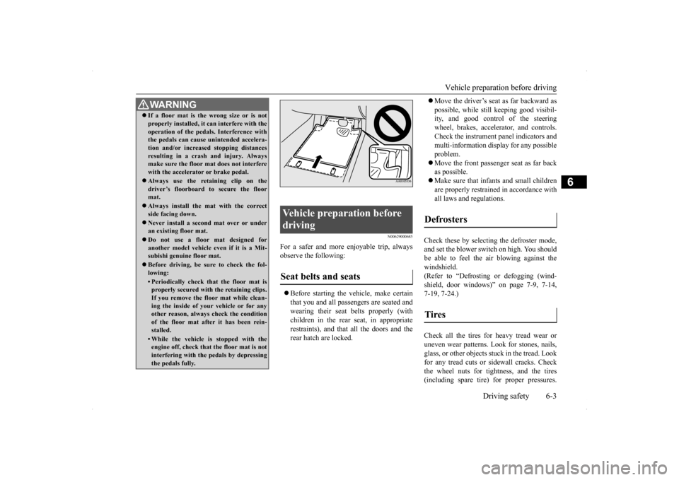
WA R N I N G If a floor mat is the wrong size or is not properly installed, it can interfere with the operation of the pedals. Interference with the pedals can cause unintended accelera- tion and/or increased stopping distancesresulting in a crash and injury. Always make sure the floor mat does not interfere with the accelerator or brake pedal. Always use the retaining clip on the driver’s floorboard to secure the floormat. Always install the mat with the correct side facing down. Never install a second mat over or under an existing floor mat. Do not use a floor mat designed for another model vehicle ev
en if it is a Mit-
subishi genuine floor mat. Before driving, be sure to check the fol- lowing:• Periodically check that the floor mat isproperly secured with the retaining clips. If you remove the floor mat while clean-ing the inside of your vehicle or for any other reason, always check the condition of the floor mat after it has been rein-stalled.• While the vehicle is stopped with the engine off, check that the floor mat is not interfering with the pedals by depressingthe pedals fully.
Vehicle preparation before driving Seat belts and seats
Defrosters Tires
BK0200700US.bo
ok 3 ページ 2013年2月15日 金曜日 午後12時17分
Page 335 of 422
If the vehicle breaks down 8-2 For emergencies
8
N00836300204
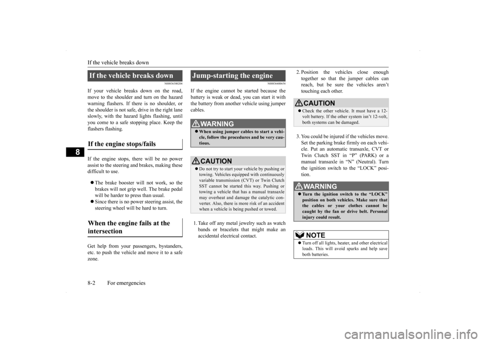
If your vehicle breaks down on the road, move to the shoulder and turn on the hazardwarning flashers. If there is no shoulder, or the shoulder is not safe, drive in the right lane slowly, with the hazard lights flashing, untilyou come to a safe stopping place. Keep the flashers flashing. If the engine stops, there will be no power assist to the steering and brakes, making these difficult to use. The brake booster will not work, so the brakes will not grip well. The brake pedalwill be harder to press than usual. Since there is no power steering assist, the steering wheel will be hard to turn.
Get help from your passengers, bystanders, etc. to push the vehicl
e and move it to a safe
zone.
N00836400654
If the engine cannot be started because the battery is weak or dead, you can start it withthe battery from another vehicle using jumper cables. 1. Take off any metal jewelry such as watch bands or bracelets that might make an accidental electrical contact.
2. Position the vehicles close enough together so that the jumper cables can reach, but be sure the vehicles aren’t touching each other. 3. You could be injured if the vehicles move. Set the parking brake firmly on each vehi- cle. Put an automatic transaxle, CVT or Twin Clutch SST in “P” (PARK) or amanual transaxle in “N” (Neutral). Turn the ignition switch to the “LOCK” posi- tion.
If the vehicle breaks down If the engine stops/fails When the engine fails at the intersection
Jump-starting the engine
WA R N I N G When using jumper cables to start a vehi- cle, follow the procedures and be very cau- tious. CAUTION Do not try to start your vehicle by pushing or towing. Vehicles equipped with continuously variable transmission (CVT) or Twin Clutch SST cannot be started this way. Pushing ortowing a vehicle that has a manual transaxle may overheat and damage the catalytic con- verter. Also, there is more risk of an accidentwhen a vehicle is being pushed or towed.
CAUTION Check the other vehicle. It must have a 12- volt battery. If the other system isn’t 12-volt, both systems can be damaged.WA R N I N G Turn the ignition switch to the “LOCK” position on both vehicles. Make sure thatthe cables or your clothes cannot be caught by the fan or drive belt. Personal injury could result. NOTE
Turn off all lights, heater, and other electrical loads. This will avoid sparks and help saveboth batteries.
BK0200700US.bo
ok 2 ページ 2013年2月15日 金曜日 午後12時17分
Page 351 of 422
Service precautions 9-2 Vehicle care and maintenance
9
N00937301397
Taking regular care of your vehicle will pre- serve its value and appearance as long as pos-sible. You can do some of the maintenance work yourself, and the rest should only be per- formed by an authorized Mitsubishi Motorsdealer or a repair facility of your choice.If you discover a malfunction or other prob- lem, have it corrected by an authorized Mit- subishi Motors dealer or a repair facility ofyour choice. This section describes the maintenance inspections that you can do yourself, if you sodesire. Follow the instructions and precau- tions for each procedure.
Have you purchased the Mitsubishi Motors Diamond Care Protection Plan? The Plan supplements your new vehicle warranties. See your authorized Mitsubishi Motors dealerfor details.
N00937400405
The catalytic converter requires you to useunleaded fuel only. Leaded gasoline will destroy the emission-control effectiveness of the converter. Normally, the catalytic converter does not require maintenance. However, it is important to keep the engine properly tuned for the con- verter to continue to work properly.
Service precautions
WA R N I N G When checking or servicing the inside of the engine compartment, be sure theengine is stopped and has had a chance to cool down. If you need to work in the engine compart- ment with the engine running, be espe-cially careful that your clothing, hair, etc. does not get caught in
the fan, drive belts,
or other moving parts.
The fan can turn on automatically even if the engine is not running. Turn the igni- tion switch to the “LOCK” position to be safe while you work in the engine com- partment. Do not smoke or allow open flames around fuel or the battery. The fumes are flamma-ble. Be extremely careful when working around the battery. It contains poisonous and corrosive sulfuric acid. Do not get under your vehicle while it is on a jack. Always use properly rated automotivejack stands. Handling your vehicle’s parts and materi- als in the wrong way can injure you. Ask an authorized Mitsubishi Motors dealer or a repair facility of your choice if youhave questions. WA R N I N G
Catalytic converter
BK0200700US.bo
ok 2 ページ 2013年2月15日 金曜日 午後12時17分
Page 363 of 422
Power steering fluid (if so equipped) 9-14 Vehicle care and maintenance
9
N00939000388
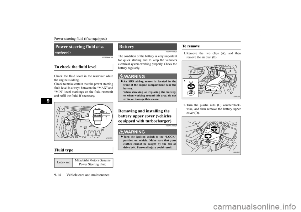
Check the fluid level in the reservoir while the engine is idling. Check to make certain that the power steering fluid level is always between the “MAX” and“MIN” level markings on the fluid reservoirand refill the fluid, if necessary.
N00939100826
The condition of the battery is very importantfor quick starting and to keep the vehicle’selectrical system working properly. Check the battery regularly.
N00901300025
1. Remove the two clips (A), and thenremove the air duct (B). 2. Turn the plastic nuts (C) counterclock- wise, and then remove the battery uppercover (D).
Power steering fluid
(if so
equipped)To check the fluid level
Fluid type
Lubricant
Mitsubishi Motors Genuine
Power Steering Fluid
Battery
WA R N I N G An SRS airbag sensor is located in the front of the engine compartment near the battery. When checking or replacing the battery,or when working around this area, do not strike or damage this sensor.
Removing and installing the battery upper cover (vehicles equipped with turbocharger)
WA R N I N G Turn the ignition switch to the “LOCK” position on vehicle. Make sure that your clothes cannot be caught by the fan or drive belt. Personal injury could result.
To remove
BK0200700US.bo
ok 14 ページ 2013年2月15日 金曜日 午後12時17分
Page 419 of 422
Alphabetical index 12-4
12
Manual transaxle oil
..............
9-10
, 11-6
Rear axle oil
..........................
9-11
, 11-6
Transfer oil
...........................
9-11
, 11-6
Operation under adverse driving conditions
...
8-15 Outside rearview mirrors
.....................
5-52
Overheating
......................
...................
8-4
P
Parking
.........................
.......................
6-6
Parking brake
................
.................
5-49
Parking brake break-in
....................
9-24
Parking brake lever stroke
...............
9-24
Polishing
.......................
.....................
9-51
Power brakes
.....................
.................
5-86
Power door locks
...............
.................
5-38
Power outlet
..................
...................
5-183
Power steering
Fluid
.....................
...............
9-14
, 11-6
System
.....................
.....................
5-90
Power windows
.................
.................
5-44
Puncture (Tire changing)
.......................
8-6
R
Radiator cap
......................
...................
9-9
Radio
General information about your radio 7-60
Rain sensor
..................
5-153
, 5-154
, 5-155
Rear hatch
.......................
...................
5-40
Inside rear hatch release
...................
5-41
Rear shelf panel
...............
.................
5-190
Rear side-marker lights
Bulb capacity
..................
................
9-33
Replacement
...................
................
9-43
Rear turn signal lights
Bulb capacity
..................
................
9-33
Replacement
...................
................
9-43
Rear window defogger switch
............
5-157
Rear-view camera
.............................
5-104
Rearview mirror
Inside
......................
.......................
5-50
Outside
.......................
...................
5-52
Refrigerant (air conditioning)
...............
11-6
Replacement of light bulbs
...................
9-33
Replacing tires and wheels
...................
9-22
Reporting Safety Defects
.....................
10-2
S
Safe driving techniques
.........................
6-4
Seat
............................
........................
4-2
Arm rest
......................
....................
4-5
Front seats
...................
....................
4-3
Heated seats
....................
.................
4-5
Rear seats
....................
....................
4-5
Seats and restraint systems
................
4-2
Seat belt
........................
.......................
4-9
Adjustable seat belt shoulder anchor
.4-13
Child restraint
...............
.................
4-15
Driver?s seat belt reminder/warning
.4-12
Force limiter
.................
.................
4-15
Front passenger seat belt warning light
.....
4-13Maintenance and inspection
.............
4-22
Pre-tensioner
.................
.................
4-14
Seat belt extender
...........................
4-14
Seat belt instructions
.......................
4-10
Seat belt use during pregnancy
.........
4-14
Service brake
.....................
.................
5-85
Service precautions
...............
................
9-2
Snow tires
.....................
.....................
9-23
Spark plugs
...................
.....................
9-25
SST (Sportronic Shift Transmission)
....
5-70
Steering
Power steering fluid
...............
9-14
, 11-6
Tilt lock lever
................
.................
5-50
Wheel lock
............................
5-20
, 5-55
Storage spaces
...................
...............
5-187
Sun roof
........................
.....................
5-46
Sun visors
.....................
...................
5-182
Supplemental Restraint System
............
4-23
How the Supplement Restraint Systemworks
.....................
.....................
4-25
Servicing
..................
.....................
4-37
Warning light/display
......................
4-29
BK0200700US.bo
ok 4 ページ 2013年2月15日 金曜日 午後12時17分