2014 MITSUBISHI LANCER EVOLUTION tow
[x] Cancel search: towPage 132 of 338

S-AWC (Super-All Wheel Control)
Features and controls 5-71
5
N00541300036
S-AWC is an integrated vehicle dynamics control system that helps enhance drivingperformance, cornering performance, and vehicle stability over a wide range of driving conditions through integrated management ofthe ACD, the AYC, the anti-lock braking sys- tem, and the active stability control (ASC).
Please read this section in conjunction with the following sections. ACD (Active center differential system)
P.5-71AYC (Active yaw control system)
P.5-72
Anti-lock braking system
P.5-74
Active stability control (ASC)
P.5-76
N00541400011
The ACD is a system
that improves accelera-
tion performance and straight-ahead stabilityby regulating the differential limiting action
CAUTION Always use tires of the same size, same type, and same brand, and which have no wear dif- ferences. Using tires that differ in size, type, brands or the degree of wear, will increase the differential oil temperature, resulting inpossible damage to the driving system. Fur- ther, the drive train will be subjected to excessive loading, possibly leading to oilleakage, component seizure, or other serious problems.
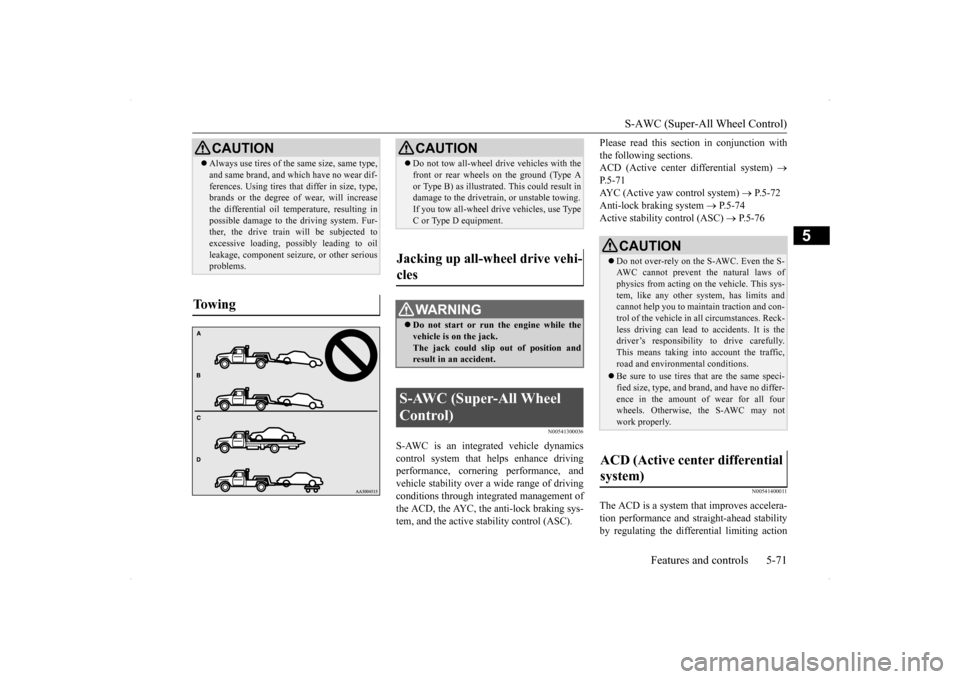
To w i n g
CAUTION Do not tow all-wheel dr
ive vehicles with the
front or rear wheels on the ground (Type A or Type B) as illustrated. This could result in damage to the drivetrain, or unstable towing. If you tow all-wheel drive vehicles, use TypeC or Type D equipment.
Jacking up all-wheel drive vehi- cles
WA R N I N G Do not start or run the engine while the vehicle is on the jack. The jack could slip out of position andresult in an accident.
S-AWC (Super-All Wheel Control)
CAUTION Do not over-rely on the S-AWC. Even the S- AWC cannot prevent the natural laws ofphysics from acting on the vehicle. This sys- tem, like any other system, has limits and cannot help you to maintain traction and con-trol of the vehicle in all circumstances. Reck- less driving can lead to accidents. It is the driver’s responsibility to drive carefully.This means taking into account the traffic, road and environmental conditions. Be sure to use tires that are the same speci- fied size, type, and brand, and have no differ- ence in the amount of wear for all fourwheels. Otherwise,
the S-AWC may not
work properly.
ACD (Active center differential system)
BK0200800US.bo
ok 71 ページ 2013年2月14日 木曜日 午後2時28分
Page 190 of 338

Combination headlights and dimmer switch
Features and controls 5-129
5
N00550000185
You can flash the high beams by pulling the lever gently toward you (2). The lights willgo back to normal when you let go. While the high beam is on, you will see a blue light on the instrument panel.
N00563201159
This function turns on the front side-marker and parking lights for about 30 seconds after the UNLOCK button (A) on the remote con-trol transmitter is pressed when the combina-tion headlights and dimmer switch is in the “OFF” or “AUTO” position (for vehicles equipped with the automatic light control).On vehicles equipped with the automatic light control, the welcome light function will oper- ate only when it is dark outside the vehicle.
N00547301136
This function turns on the headlights in thelow beam setting for about 30 seconds afterthe ignition switch is turned to the “LOCK” position. 1. Turn the combination headlights and dim- mer switch to the “OFF” or “AUTO”position (for vehicles equipped with the automatic light control). 2. Turn the ignition switch to the “LOCK”position. Also, if a key was used to start the engine, remove the key from the igni- tion switch.
Headlight flasher
NOTE
You can flash the high beams by pulling the lever toward you, even if the light switch isoff. If you turn the lights off with the head lights set to high-beam illumination, the headlights are automatically returned to their low-beam setting when the light switch is next turned to the “ ” position.
Welcome light
NOTE
While the welcome light function is operat- ing, perform one of the following operations to cancel the function. • Push the LOCK button (B) on the remote control transmitter. • Turn the combination headlights and dim- mer switch to the “ ” or “ ” position. • Turn the ignition switch to the “ON” posi- tion.
It is possible to modify functions as follows: • The headlights can be set to come on in the low beam setting.
• The welcome light function can be deacti- vated. For details, consult a Mitsubishi Motors dealer.
Coming home light
NOTE
BK0200800US.book
129 ページ 2013年2月14日 木曜日 午後2時28分
Page 191 of 338

Combination headlights and dimmer switch 5-130 Features and controls
5
3. Within 60 seconds of turning the ignition switch to the “LOCK” position, pull the turn signal lever toward you. 4. The headlights will come on in the low beam setting for about 30 seconds. Afterthe headlights go off, the headlights can be turned on again in the low beam setting for about 30 seconds by pulling the turnsignal lever toward you within 60 secondsof turning the ignition switch to the “LOCK” position. To turn on the head- lights again after 60 seconds of turningthe ignition switch to the “LOCK” posi- tion, repeat the process from step 1.
N00542800038
The direction of the headlight beam (thedirection which the light shines in) alters according to the number of people and theload in the vehicle. Lower the headlight angle if it is too high due to the number of people and/or the load in the vehicle so that the head-lights’ glare does not distract the drivers ofapproaching vehicles. First set the light switch to the “ ” position, then turn the headlight leveling switch knob to lower thebeam. The greater the number on the head- light leveling switch knob, the lower the beam will point.
Set the switch to the appropriate position so that the headlight beam is level with the road.
NOTE
While the coming home light function is operating, perform one of the following operations to cancel the function. • Pull the turn signal lever toward you.
• Turn the combination headlights and dim- mer switch to the “ ” or “ ” position. • Turn the ignition switch to the “ON” posi- tion.
It is possible to modify functions as follows: • The time that the headlights remain on can be changed. • The coming home light function can be deactivated. For details, consult a Mitsubishi Motors dealer.
Headlights leveling switch
(if so
equipped)
NOTE
WA R N I N G To avoid distraction while driving, always perform headlight adjustments before vehicle operation.NOTE
Start adjusting when the knob is at the “0” position (when the beam is at its highest). Keep the knob in the “0” position except when using the knob to lower the headlight beam angle. Always return the knob to the “0” position when the load is removed and the people have left the vehicle.
BK0200800US.book
130 ページ 2013年2月14日 木曜日 午後2時28分
Page 196 of 338

Wiper and washer switch
Features and controls 5-135
5
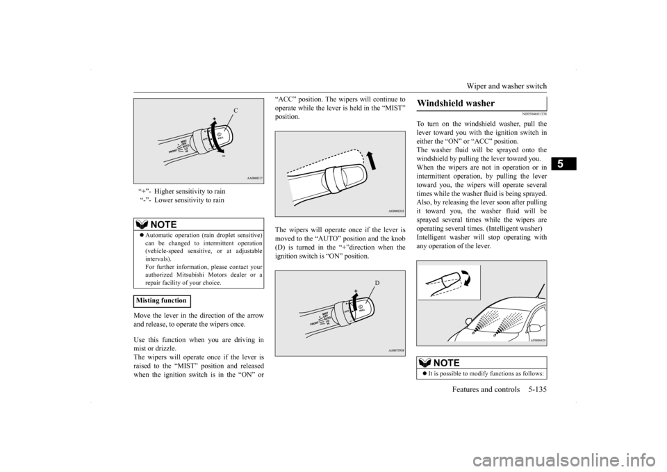
Move the lever in the direction of the arrow and release, to operate the wipers once. Use this function when you are driving in mist or drizzle. The wipers will operate once if the lever is raised to the “MIST” position and releasedwhen the ignition switch is in the “ON” or
“ACC” position. The wipers will continue to operate while the lever is held in the “MIST” position. The wipers will operate once if the lever is moved to the “AUTO” position and the knob (D) is turned in the “+”direction when the ignition switch is “ON” position.
N00504601338
To turn on the windshield washer, pull thelever toward you with the ignition switch ineither the “ON” or “ACC” position. The washer fluid will be sprayed onto the windshield by pulling the lever toward you.When the wipers are not in operation or in intermittent operation, by pulling the lever toward you, the wipers will operate severaltimes while the washer fluid is being sprayed.Also, by releasing the lever soon after pulling it toward you, the washer fluid will be sprayed several times while the wipers areoperating several times. (Intelligent washer) Intelligent washer will stop operating with any operation of the lever.
“+”- Higher sensitivity to rain “-”- Lower sensitivity to rain
NOTE
Automatic operation (rain droplet sensitive) can be changed to intermittent operation (vehicle-speed sensitive, or at adjustableintervals). For further information, please contact your authorized Mitsubishi Motors dealer or arepair facility of your choice.
Misting function
C
D
Windshield washer
NOTE
It is possible to modify functions as follows:
BK0200800US.book
135 ページ 2013年2月14日 木曜日 午後2時28分
Page 230 of 338

6
Driving safetyFuel economy.............................
.......................................................6-2
Driving, alcohol and dr
ugs ...............................................................6-2
Floor mat....................................
.......................................................6-2
Vehicle preparation before driving ...................................................6-3Safe driving techniqu
es...........................................
..........................6-4
Driving during cold weat
her .............................................................6-4
Braking ......................................
.......................................................6-5
Parking .......................................
.......................................................6-6
Loading information
...............................................
..........................6-6
Cargo loads ......................
...............................................................6-10
Trailer towing ..................
...............................................................6-10
BK0200800US.bo
ok 1 ページ 2013年2月14日 木曜日 午後2時28分
Page 235 of 338

Parking 6-6 Driving safety
6
N00629600320
When parking on a hill, set the parking brake, and turn the front wheels toward the curb on adownhill, or away from the curb on an uphill. If necessary, apply chocks to wheels. Place the gearshift lever into the “R” (Reverse) position when parking on a down-hill slope, into the 1s
t position when parking
on an uphill slope. Be sure that the parking brake is firmly set when parked and that the gearshift lever is in the “P” (PARK) position.When parking on a hill, it is important to set the parking brake before moving the gearshift lever to the “P” (PARK) position. This pre-vents loading the parking brake against the transmission gear. When this happens, it is difficult to move the gearshift lever out of the“P” (PARK) position.
Never leave the engi
ne running while you
take a short sleep/rest. Also, never leave the engine running in a closed or poorly venti- lated place. Your front bumper can be damaged if you scrape it over curbs or parking stop blocks.Be careful when traveling up or down steep slopes where your bumper can scrape the road.
When leaving the vehicle unattended, always carry the key and lock all doors.Always try to park your vehicle in a well lit area.
N00629900365
It is very important to know how much weight your vehicle can carry. This weight is called the vehicle capacity weight and includes the weight of all occupants, cargo(including the roof load) and non-factory- installed options. The tire and loading infor- mation placard located on the driver’s doorsill of your vehicle will show how much weight it may properly carry. It is important to familiarize yourself with the following terms before loading your vehicle:
Parking Parking on a hill For vehicles with manual trans- axle For vehicles with Twin Clutch SST
Parking with the engine run- ning
WA R N I N G Leaving the engine running risks injury or death from accidentally moving the gear-shift lever (manual transaxle) or the gear- shift lever (Twin Clutch SST) or from the accumulation of toxic exhaust fumes in thepassenger compartment.
Where you park
WA R N I N G Do not park your vehicle in areas where combustible materials such as dry grass orleaves can come in contact with a hot exhaust, since a fire could occur.
When leaving the vehicle Loading information
WA R N I N G Never overload your vehicle. Overloading can damage your vehicle, adversely affectvehicle performance, including handling and braking, cause tire failure, and result in an accident.
BK0200800US.bo
ok 6 ページ 2013年2月14日 木曜日 午後2時28分
Page 237 of 338

Loading information 6-8 Driving safety
6
Ty p e 1 Ty p e 2
N00630201248
1.Locate the statement “The com- bined weight of occupants andcargo should never exceed XXX kg or XXX lbs.” on your vehicle’s placard.2.Determine the combined weight of the driver and passengers that will be riding in your vehicle.3.Subtract the combined weight of the driver and passengers from XXX kg or XXX lbs.4.The resulting figure equals the available amount of cargo and luggage load capacity. For exam-ple, if the “XXX” amount equals 1400 lbs. and there will be five 150 lbs. passengers in your vehi-cle, the amount of available cargo and luggage load capacity is 650 lbs. (1400 - 750 (5 x 150) = 650 lbs.)
5.Determine the combined weightof luggage and cargo being loaded on the vehicle. That weight may not safely exceed the available cargo and luggage load capacitycalculated in Step 4.6.If your vehicle will be towing atrailer, load from your trailer willbe transferred to your vehicle. Consult this manual to determine how this reduces the availablecargo and luggage load capacity of your vehicle.
Steps for Determining Correct Load Limit
NOTE
The above steps for determining correct load limit were written in accordance with U.S.A. regula- tions.Your vehicle cannot tow a trailer, so step 6 is irrelevant.
BK0200800US.bo
ok 8 ページ 2013年2月14日 木曜日 午後2時28分
Page 239 of 338

Cargo loads 6-10 Driving safety
6
N00629700507
To determine the cargo load capacity for your vehicle, subtract the weight of all vehicleoccupants from the vehicle capacity weight. For added information, if needed, refer to “Steps for Determining Correct Load Limit”on page 6-8.DO NOT USE the Gross Vehicle Weight Rat- ing and Gross Axle Weight Rating numbers listed on the safety certification label (A)located on the inside sill of the driver’s door as the guide for passengers and/or cargo weight.
N00629801332
Cargo loads Cargo load precautions
WA R N I N G To reduce the risk of serious injury or death, the combined weights of the driver, passengers and cargo and must never exceed the vehicle capacity weight. Exceeding the vehicle capacity weight will adversely affect vehicle performance, including handling and braking, and maycause an accident. Do not load cargo or luggage higher than the top of the seatback. Be sure that your cargo or luggage cannot move when your vehicle is in motion.Having either the rear view blocked, or your cargo being thrown inside the cabin if you suddenly have to brake can cause aserious accident or injury or death. Put cargo or luggage in the cargo area of your vehicle. Try to spread the weight evenly.
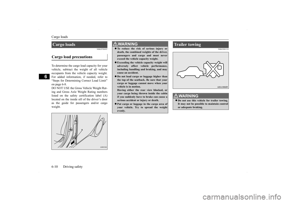
Trailer towing
WA R N I N G Do not use this vehicle for trailer towing. It may not be possible to maintain controlor adequate braking.
BK0200800US.bo
ok 10 ページ 2013年2月14日 木曜日 午後2時28分