Page 177 of 218

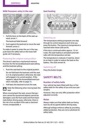
Replacing
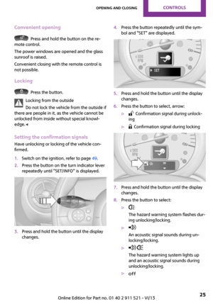
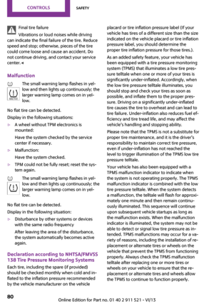
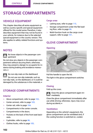
MINI Countryman1.Push the lamp to the left in the catch of the
lamp housing using the screwdriver, ar‐
row 1.2.Take out the lamp, arrow 2.3.Replace the bulb.4.Insert the lamp.
MINI Paceman
1.Push the lamp to the left in the catch of the
lamp housing using the screwdriver, ar‐
row 1.2.Take out the lamp, arrow 2.3.Replace the bulb.4.Insert the lamp.
Center brake lamp
This lamp uses LED technology for operation. In
case of a defect, please contact your service
center or a workshop that works according to
the repair procedures of the manufacturer of
your MINI with correspondingly trained person‐
nel.
Changing wheels
Notes
The vehicle may be equipped with conven‐
tional tires with the Mobility System, refer to
page 161, or with run-flat tires, refer to
page 160.
No spare tire is available in the case of a flat
tire.
Suitable tools for changing the wheels are
available from the service center as an acces‐
sory.
Jacking points for the vehicle jack MINI Countryman:
MINI Paceman:
The jacking points for the vehicle jack are lo‐
cated in the positions shown.
Seite 177Replacing componentsMobility177
Online Edition for Part no. 01 40 2 911 521 - VI/13
Page 178 of 218

Vehicle batteryMaintenance
The battery is maintenance-free, i.e., the elec‐
trolyte will last for the life of the battery in tem‐
perate climate conditions.
The service center will be happy to answer any
questions on the battery.
Battery replacement Use approved vehicle batteries
Only use vehicle batteries that have been
approved for your vehicle by the manufacturer;
otherwise, the vehicle could be damaged and
systems or functions may not be fully availa‐
ble. ◀
Have the vehicle battery registered by the serv‐
ice center after it is replaced to ensure that all
comfort functions are available without restric‐
tions and that any associated Check Control
messages are no longer displayed.
Charging the battery
Note Do not connect the charger to the socket
Do not connect the battery charger to the
socket installed in the vehicle at the factory as
this could damage the battery. ◀
Only charge the battery in the vehicle when the engine is switched off. Connections, refer to
page 180.
General information Ensure that the battery is sufficiently charged to
achieve the full battery life.
It may be necessary to charge the battery in
the following cases:▷When the vehicle is frequently used to
travel short distances.▷When the vehicle has not been driven for
more than one month.Power failure
After a temporary power failure, some equip‐
ment will be restricted in its use and will need
to be reinitialized. In addition, certain individual
settings will be lost and must be updated:▷Time and date: the values must be up‐
dated, refer to page 63.▷Radio: the stations need to be stored again,
refer to page 126.▷Glass sunroof, electrical: it may only be pos‐
sible to tilt the roof. The system needs to be
initialized. Contact the service center.
Disposing of old batteries
Have used batteries disposed of by the
service center after they are replaced or
take them to a recycling center.
Maintain the battery in an upright position for
transport and storage. Secure the battery so
that it does not tip over during transport.
Fuses Replacing fuses
Never attempt to repair a blown fuse and
do not replace a defective fuse with a substi‐
tute of another color or amperage rating; this
could lead to a circuit overload, ultimately re‐
sulting in a fire in the vehicle. ◀
Fuses should be replaced by the service center.
Information on the fuses can be found on the
inside of the covers.
Seite 178MobilityReplacing components178
Online Edition for Part no. 01 40 2 911 521 - VI/13
Page 179 of 218
In the engine compartment
Opening the cover
Press the snap lock.
In interior
On the right side of the footwell.
Opening the cover
Push out at the recess.
Seite 179Replacing componentsMobility179
Online Edition for Part no. 01 40 2 911 521 - VI/13
Page 180 of 218

Breakdown assistanceVehicle equipment
This chapter describes all series equipment as
well as country-specific and special equipment
offered for this model series.Therefore, it also
describes equipment that may not be found in
your vehicle, for instance due to the selected
special equipment or the country version. This
also applies to safety-related functions and sys‐
tems.
Hazard warning flash‐
ers
The button is located on the speedometer.
Warning triangle
Under the loading edge in the cargo area.
To remove, open the two fasteners.
First aid kit
Some of the articles contained in the first aid kit
have a limited service life. Therefore, check the
use-by dates of the contents regularly and re‐
place the items before they expire.
The first aid kit is located in the left side trim on
the cargo area floor or under the loading floor.
Roadside Assistance Service availability
Roadside Assistance can be reached around the
clock in many countries. You can obtain assis‐
tance there in the event of a vehicle break‐
down.
Roadside Assistance A phone number for Roadside Assistance can
be displayed, refer to page 142, via the radio.
Jump-starting NotesIf the battery is discharged, the engine can be
started using the battery of another vehicle and
two jumper cables. In the same way, you can
help jump-start another vehicle. Only use
Seite 180MobilityBreakdown assistance180
Online Edition for Part no. 01 40 2 911 521 - VI/13
Page 181 of 218

jumper cables with fully insulated clamp han‐
dles.
To prevent personal injury or damage to both
vehicles, adhere strictly to the following proce‐
dure.
Do not touch live parts
To avoid the risk of potentially fatal injury,
always avoid all contact with electrical compo‐
nents while the engine is running. ◀
Preparation1.Check whether the battery of the other ve‐
hicle has a voltage of 12 volts and approxi‐
mately the same capacitance in Ah. This in‐
formation can be found on the battery.2.Switch off the engine of the assisting vehi‐
cle.3.Switch off any electronic systems/power
consumers in both vehicles.
Bodywork contact between vehicles
There must not be any contact between
the bodies of the two vehicles, otherwise there
is a danger of shorting. ◀
Connecting jumper cables
Connecting order
Connect the jumper cables in the correct
order; otherwise, there is the danger of injury
from sparking. ◀1.Open the battery cover in the engine com‐
partment to access the positive terminal.2.Unlock the tabs of the positive terminal
cover on the left and right, arrows 1, and
raise the cover, arrow 2.3.Attach one terminal clamp of the positive
jumper cable to the positive terminal of the
battery or to a starting aid terminal of the
vehicle providing assistance.4.Attach the second clamp of the positive
jumper cable to the positive terminal of the
battery of the vehicle to be started.5.Attach one terminal clamp of the negative
jumper cable to the negative terminal of
the battery, or to the corresponding engine
or body ground of the vehicle providing as‐
sistance.6.Attach the second clamp of the negative
jumper cable to the negative terminal ofSeite 181Breakdown assistanceMobility181
Online Edition for Part no. 01 40 2 911 521 - VI/13
Page 182 of 218

the battery, or to the engine or body
ground of the vehicle to be started.
Body ground:
Starting the engine
Never use spray fluids to start the engine.
1.Start the engine of the assisting vehicle and
let it run for several minutes at a slightly in‐
creased idle speed.2.Start the engine of the vehicle being started
in the usual way.
If the first starting attempt is not successful,
wait a few minutes before making another
attempt in order to allow the discharged
battery to recharge.3.Let both engines run for several minutes.4.Disconnect the jumper cables in the reverse
order.
Check the battery and recharge if necessary.
Tow-starting and towing
Notes Observe applicable laws and regulations
Observe applicable laws and regulations
for tow-starting and towing. ◀
No additional passengers
Do not transport any passengers other
than the driver in a vehicle that is being
towed. ◀
Using a tow fitting
The screw-in tow fitting must always be carried
in the vehicle. It can be screwed in at the front
or rear of the MINI.
The tow fitting is stowed in the following loca‐
tion, depending on the equipment:▷Under the right or left front seat.▷In the pouch of the wheel change set in the
cargo area.
Tow fitting, information on use
▷Use only the tow fitting provided with
the vehicle and screw it all the way in.▷Use the tow fitting for towing on paved
roads only.▷Avoid lateral loading of the tow fitting, e.g.,
do not lift the vehicle by the tow fitting.
Otherwise, damage to the tow fitting and the
vehicle can occur. ◀
Access to the screw thread Push out the tow fitting cover at the appropri‐
ate recess in the bumper.
Front
Seite 182MobilityBreakdown assistance182
Online Edition for Part no. 01 40 2 911 521 - VI/13
Page 183 of 218

MINI Countryman: rear
MINI Paceman: rear
Being towedFollow the towing instructions
Follow all towing instructions, or vehicle
damage or accidents may occur. ◀
▷Make sure that the ignition is switched on;
otherwise, the low beams, tail lamps, turn
signals, and windshield wipers may be un‐
available.▷Do not tow the vehicle with the rear axle
tilted, as the front wheels could turn.▷When the engine is stopped, there is no
power assist. Consequently, more force
needs to be applied when braking and
steering.▷Larger steering wheel movements are re‐
quired.▷Switch on the hazard warning system, de‐
pending on local regulations.Manual transmission
Gearshift lever in neutral position.
Automatic transmission Towing vehicles with an automatic trans‐
mission
Only transport vehicles with an automatic
transmission on tow trucks or with raised front
wheels; otherwise, the transmission may be
damaged. ◀
Towing with a tow bar Light towing vehicle
The towing vehicle must not be lighter
than your vehicle, or it will not be possible to
control vehicle response. ◀
Correctly attach the tow bar
Only secure the tow bar on the tow fit‐
tings; damage can occur when it is secured on
other parts of the vehicle. ◀
The tow fittings used should be on the same
side on both vehicles.
Should it prove impossible to avoid mounting
the tow bar at an offset angle, please observe
the following:▷Clearance and maneuvering capability will
be sharply limited during cornering.▷The tow bar will generate lateral forces if it
is attached offset.
Towing with a tow rope
When starting to tow the vehicle, make sure
that the tow rope is taut.
To avoid jerking and the associated stresses on
the vehicle components when towing, always
use nylon ropes or nylon straps.
Attaching the tow rope correctly
Only secure the tow rope on the tow fit‐
ting; otherwise, damage can occur when it is
secured on other parts of the vehicle. ◀
Seite 183Breakdown assistanceMobility183
Online Edition for Part no. 01 40 2 911 521 - VI/13
Page 184 of 218

With a tow truck: vehicles without ALL4all-wheel drive
Do not lift the vehicle
Do not lift the vehicle by the tow fitting or
body and chassis parts; otherwise, damage
may result. ◀
MINI Countryman:
MINI Paceman:
Have the vehicle transported with a tow truck
with a so-called lift bar or on a flat bed.
With a tow truck: vehicle with ALL4 all-wheel drive
Do not lift the vehicle
Do not lift the vehicle by the tow fitting or
body and chassis parts; otherwise, damage
may result. ◀
Note for vehicles with ALL4 all-wheel
drive
Do not tow a vehicle with ALL4 all-wheel drive
with just the front or rear axle raised; other‐
wise, the wheels could lock up and the transfer
case could be damaged. ◀
MINI Countryman:
MINI Paceman:
Only transport the vehicle on a flat-bed.
Tow-starting
If possible, do not tow-start the vehicle but
start the engine by jump-starting, refer to page 180. Vehicles with a catalytic converter
should only be tow-started when the engine is
cold; vehicles with an automatic transmission
cannot be tow-started.
1.Switch on the hazard warning system and
comply with local regulations.2.Switch on the ignition, refer to page 49.3.Shift into 3rd gear.4.Have the vehicle tow-started with the
clutch is depressed and then slowly release
the clutch. After the engine starts, immedi‐
ately depress the clutch completely again.Seite 184MobilityBreakdown assistance184
Online Edition for Part no. 01 40 2 911 521 - VI/13