Page 97 of 240
SafetyVehicle features and op‐
tions
This chapter describes all standard, country-
specific and optional features offered with theseries. It also describes features that are not
necessarily available in your car, e. g., due to
the selected options or country versions. This
also applies to safety-related functions and sys‐
tems.
Airbags
1Front airbag, driver2Front airbag, front passenger3Head airbag4Side airbag5Knee airbagsFront airbags
Front airbags help protect the driver and front
passenger by responding to frontal impacts in
which safety belts alone would not provide ad‐
equate restraint.Side airbags
In a lateral impact, the side airbag supports the
side of the body in the chest and lap area.
Head airbags
In a lateral impact, the head airbag supports
the head.Seite 93SafetyCONTROLS93
Online Edition for Part no. 01 40 2 957 280 - X/14
Page 98 of 240

Ejection MitigationThe system consists of an extension of the head
airbag system and is a kind of curtain. The sys‐
tem is activated under certain conditions in the
event of a rollover accident, and should help to
prevent the vehicle occupant from being
thrown out of the vehicle.
Knee airbag
The knee airbag supports the legs in a frontal
impact.
Protective action
Airbags are not triggered in every impact situa‐
tion, e.g., in less severe accidents or rear-end
collisions.
Information on how to ensure the opti‐
mal protective effect of the airbags▷Keep at a distance from the airbags.▷Always grasp the steering wheel on the
steering wheel rim, holding your hands at
the 3 o'clock and 9 o'clock positions, to
keep the risk of injury to your hands or
arms as low as possible when the airbag is
triggered.▷There should be no person, animals, or ob‐
jects between an airbag and a person.▷Do not use the cover of the front airbag on
the front passenger side as a storage area.▷Dashboard and windshield on the front
passenger side must stay clear - do not at‐
tach adhesive labels or coverings and do
not attach brackets or cables, e. g., for GPS
devices or' mobile phones.▷Make sure that the front passenger is sitting
correctly, i.e., keeps his or her feet and legs
in the footwell; otherwise, leg injuries might
occur when front airbag is activated.▷Do not place slip covers, seat cushions or
other objects on the front passenger seat
that are not approved specifically for seats
with integrated side airbags.▷Do not hang pieces of clothing, such as
jackets, over the backrests.▷Make sure that occupants keep their heads
away from the side airbag and do not rest
against the head airbag; otherwise, injuries
might occur when airbag is activated.▷Do not remove the airbag system.▷Do not remove the steering wheel.▷Do not apply adhesive materials to the air‐
bag cover panels, do not cover them or
modify them in any way.▷Never modify either the individual compo‐
nents or the wiring in the airbag system.
This also applies to steering wheel covers,
the dashboard, the seats, the roof pillars
and the sides of the roofliner. ◀
Even when you follow all instructions very
closely, injury from contact with the airbags
cannot be ruled out in certain situations.
The ignition and inflation noise may lead to
short-term and, in most cases, temporary hear‐
ing impairment in sensitive individuals.
Malfunction, deactivation and after de‐
ploying the airbags
Do not touch the individual components imme‐
diately after the system has been triggered;
otherwise, you may risk burns.
Only have the airbags checked, repaired or dis‐
mantled and the airbag generator scrapped by
the service center or an authorized repair shop
for handling explosives.
Non-professional attempts to service the sys‐
tem could lead to failure in an emergency or
unintentional activation of the airbag - both
may lead to injury. ◀
Warnings and information on the airbags are
also found on the sun visors.
Seite 94CONTROLSSafety94
Online Edition for Part no. 01 40 2 957 280 - X/14
Page 99 of 240

Functional readiness of the airbag
system
When the ignition is reel on, the warn‐
ing lamp in the instrument cluster lights
up briefly and thereby indicates the op‐
erational readiness of the entire airbag system
and the belt tensioner.
Airbag system malfunctioning▷Warning lamp does not come on when the
ignition is turned on.▷The warning lamp lights up continuously.
In case of a malfunction have airbag sys‐
tem checked immediately.
In case of a malfunction have airbag system
checked immediately; otherwise, there is a risk
that the system does not function as expected
in case of a severe accident. ◀
Automatic deactivation of the front-
seat passenger airbags
The system reads if the front passenger seat is
occupied by measuring the human body's re‐
sistance.
Front, knee and side airbag on the front pas‐
senger's side are either activated or deacti‐
vated.
Leave feet in the footwell
Make sure that the front passenger keeps
his or her feet in the footwell; otherwise, proper
functioning of the front passenger airbag might
not be assured. ◀
Child restraint fixing system in the front
passenger seat
Before transporting a child on the front passen‐
ger seat, refer to the safety notes and instruc‐
tions for children on the front passenger seat,
see Children. ◀
Malfunction of the automatic
deactivation system
When transporting older children and adults,
the front-seat passenger airbags may be deac‐
tivated in certain sitting positions. In this case,
the indicator lamp for the front-seat passenger
airbags lights up.
In this case, change the sitting position so that
the front-seat passenger airbags are activated
and the indicator lamp goes out.
If it is not possible to activate the airbags, have
the person sit in the rear.
To enable correct recognition of the occupied
seat cushion▷Do not attach covers, cushions, ball mats or
other items to the front passenger seat un‐
less they are specifically recommended by
your vehicle's manufacturer.▷Do not place any electronic devices on the
passenger seat if a child restraint system is
to be installed on it.▷Do not place objects under the seat that
could press against the seat from below.▷No moisture in or on the seat.
Indicator lamp for the front-seat
passenger airbags
The indicator lamp for the front-seat passenger
airbags indicates the operating state of the
front-seat passenger airbags.
The lamp indicates whether the airbags are ei‐
ther activated or deactivated.
Seite 95SafetyCONTROLS95
Online Edition for Part no. 01 40 2 957 280 - X/14
Page 100 of 240

▷The indicator lamp lights up
when a child is properly
seated in a child restraint fix‐
ing system or when the seat
is empty. The airbags on the
front passenger side are not
activated.▷The indicator lamp does not light up when,
e.g., a correctly seated person of sufficient
size is detected on the seat. The airbags on
the front passenger side are activated.
Detected child seats
The system generally detects children seated in
a child seat, particularly in child seats required
by NHTSA when the vehicle was manufactured.
After installing a child seat, make sure that the
indicator lamp for the front-seat passenger air‐
bags lights up. This indicates that the child seat
has been detected and the front-seat passen‐
ger airbags are not activated.
Strength of the driver's and front-seat
passenger airbag
The explosive power that activates driver's/
front passenger's airbags very much depends
on the positions of the driver's/front passeng‐
er's seat.
With a respective message appearing on Con‐
trol Display calibrate the front seats to keep the
accuracy of this function over the long-term.
Calibrating the front seats
A corresponding message appears on the Con‐
trol Display.
1.Move the respective seat all the way for‐
ward.2.Move the respective seat forward again. It
moves forward briefly.3.Readjust the seat to the desired position.
The calibration procedure is completed when
the message on the Control Display disappears.
If the message continues to be displayed, re‐
peat the calibration.
If the message does not disappear after a re‐
peat calibration, have the system checked as
soon as possible.
Unobstructed area of movement
Ensure that the area of movement of the
seats is unobstructed to avoid personal injury
or damage to objects. ◀
Tire Pressure Monitor
TPM
The concept The system monitors tire inflation pressure in
the four mounted tires. The system warns you if
there is a significant loss of pressure in one or
more tires. For this purpose, sensors in the tire
valves measure the tire inflation pressure.
Hints Tire damage due to external factors
Sudden tire damage caused by external
circumstances cannot be recognized in ad‐
vance. ◀
With use of the system observe further infor‐
mation found under Tire inflation pressure, re‐
fer to page 172.
Functional requirements
The system must have been reset with the cor‐
rect tire inflation pressure; otherwise, reliable
signaling of tire pressure loss is not assured.
Reset the system after each adjustment of the
tire inflation pressure and after every tire or
wheel change.
Always use wheels with TPM electronics to en‐
sure that the system will operate properly.Seite 96CONTROLSSafety96
Online Edition for Part no. 01 40 2 957 280 - X/14
Page 101 of 240

Status displayOn the onboard monitor, the current status of
the Tire Pressure Monitor TPM can be dis‐
played, e.g., whether or not the TPM is active.1."Vehicle info"2."Vehicle status"3. "Tire Pressure Monitor (TPM)"
The status is displayed.
Status control display Tire and system status are indicated by the
color of the tires and a text message on the
Control Display.
All wheels green System is active and will issue a warning rela‐
tive to the tire inflation pressures stored during
the last reset.
One wheel is yellowA flat tire or major drop in inflation pressure in
the indicated tire.
All wheels are yellow A flat tire or major drop in inflation pressure in
several tires.
Wheels, gray
The system cannot detect a flat tire due to a
malfunction.
Status information The status control display additionally shows
the current tire inflation pressures. It shows the
actual values read; they may vary depending
on driving style or weather conditions.
Carry out reset
Reset the system after each adjustment of the
tire inflation pressure and after every tire or
wheel change.1."Vehicle info"2."Vehicle status"3. "Perform reset"4.Start the engine - do not drive off.5.Reset the tire inflation pressure using
"Perform reset".6.Drive away.
The tires are shown in gray and the status is
displayed.
After driving faster than 19 mph/30 km/h for a
short period, the set tire inflation pressures are
accepted as reference values. The resetting
process is completed automatically while driv‐
ing. After successful completion of the reset,
the tires appear in green on the Control Display
and "Tire Pressure Monitor (TPM) active" is dis‐ played.
The progress of the reset is displayed.
You may interrupt this trip at any time. When
you continue the reset resumes automatically.
Low tire pressure message The yellow warning lamp lights up. A
Check Control message is displayed.
▷There is a flat tire or a major loss in
tire inflation pressure.▷A reset of the system was not carried out
after a wheel was changed. The system
therefore issues a warning based on the tire
pressures before the last reset.1.Reduce your speed and stop cautiously.
Avoid sudden braking and steering maneu‐
vers.2.Check whether the vehicle is fitted with
regular tires or run-flat tires.Seite 97SafetyCONTROLS97
Online Edition for Part no. 01 40 2 957 280 - X/14
Page 102 of 240

Run-flat tires, refer to page 181, are la‐
beled with a circular symbol containing the
letters RSC marked on the tire's sidewall.
Do not continue driving without run-flat
tires
Do not continue driving if the vehicle is not
equipped with run-flat tires; continued driving
may result in serious accidents. ◀
A low tire inflation pressure might turn on DSC
Dynamic Stability Control.
Actions in the event of a flat tireNormal tires
1.Identify the damaged tire.
Do this by checking the air pressure in all
four tires.
The tire pressure gauge of the Mobility Sys‐
tem, refer to page 181, can be used for this
purpose.
If the tire inflation pressure in all four tires is
correct, the Tire Pressure Monitor may not
have been initialized. In this case, initialize
the system.
If an identification is not possible, please
contact the service center.2.Fix the flat tire using the Mobility System,
refer to page 181.
Run-flat tires
Maximum speed
You may continue driving with a damaged tire at speeds up to 50 mph/80 km/h.
Continued driving with a flat tire
If continuing to drive with a damaged tire:
1.Avoid sudden braking and steering maneu‐
vers.2.Do not exceed a speed of 50 mph/80 km/h.3.Check the air pressure in all four tires at the
next opportunity.If the tire inflation pressure in all four tires is
shown to be correct, it is possible that the
Tire Pressure Monitor did not perform a re‐
set. In that case, carry out a reset.
Possible driving distance with complete loss of
tire inflation pressure:
The possible driving distance after a loss of tire
inflation pressure depends on cargo load, driv‐
ing style and road conditions.
A vehicle with an average load has a possible
driving range of approx. 50 miles/80 km.
A vehicle with a damaged tire reacts differently,
e.g., it has reduced lane stability during brak‐
ing, a longer braking distance and different
self-steering properties. Adjust your driving
style accordingly. Avoid abrupt steering ma‐
neuvers or driving over obstacles, e.g., curbs,
potholes, etc.
Because the possible driving distance depends
on how the vehicle is used during the trip, the
actual distance may be shorter or longer de‐
pending on the driving speed, road conditions,
external temperature, cargo load, etc.
Continued driving with a flat tire
Drive moderately and do not exceed a
speed of 50 mph/80 km/h.
Your car handles differently when you lose tire
inflation pressure, e.g., your lane stability is re‐
duced when braking, braking distances are lon‐
ger and the self-steering properties will
change. ◀
Final tire failure
Vibrations or loud noises while driving
can indicate the final failure of a tire. Reduce
speed and stop; otherwise, pieces of the tire
could come loose and cause an accident. Do
not continue driving and contact your service
center. ◀
Seite 98CONTROLSSafety98
Online Edition for Part no. 01 40 2 957 280 - X/14
Page 103 of 240

Required inflation pressure check
message
A Check Control message is displayed in the fol‐
lowing situations▷The system has detected a wheel change,
but no reset was done.▷Inflation was not carried out according to
specifications.▷The tire inflation pressure has fallen below
the level of the last confirmation.
In this case:
▷Check the tire pressure and correct as
needed.▷Carry out a reset of the system after a tire
change.
System limits
The system does not function properly if a reset
has not been carried out, e.g., a flat tire is re‐
ported though tire inflation pressures are cor‐
rect.
The tire inflation pressure depends on the tire's
temperature. Driving or exposure to the sun
will increase the tire's temperature, thus in‐
creasing the tire inflation pressure. The tire in‐
flation pressure is reduced when the tire tem‐ perature falls again. These circumstances may
cause a warning when temperatures fall very
sharply.
Malfunction The yellow warning lamp flashes and
then lights up continuously. A Check
Control message is displayed. No flat
tire or loss of tire pressure can be detected.
Display in the following situations:
▷A wheel without TPM electronics, such as a
compact wheel, is mounted: have the serv‐
ice center check it if needed.▷Malfunction: have the system checked by
your service center.▷TPM was unable to complete the reset. Re‐
set the system again.▷Interference through systems or devices
with the same radio frequency: after leav‐
ing the area of the interference, the system
automatically becomes active again.
Declaration according to NHTSA/FMVSS
138 Tire Pressure Monitoring System
Each tire, including the spare (if provided)
should be checked monthly when cold and in‐
flated to the inflation pressure recommended
by the vehicle manufacturer on the vehicle
placard or tire inflation pressure label. (If your
vehicle has tires of a different size than the size
indicated on the vehicle placard or tire inflation
pressure label, you should determine the
proper tire inflation pressure for those tires.) As
an added safety feature, your vehicle has been
equipped with a tire pressure monitoring sys‐
tem (TPMS) that illuminates a low tire pressure
telltale when one or more of your tires is signifi‐
cantly under-inflated. Accordingly, when the
low tire pressure telltale illuminates, you should
stop and check your tires as soon as possible,
and inflate them to the proper pressure. Driving
on a significantly under-inflated tire causes the
tire to overheat and can lead to tire failure. Un‐
der-inflation also reduces fuel efficiency and
tire tread life, and may affect the vehicle's han‐
dling and stopping ability. Please note that the
TPMS is not a substitute for proper tire mainte‐
nance, and it is the driver's responsibility to
maintain correct tire pressure, even if under-in‐
flation has not reached the level to trigger illu‐
mination of the TPMS low tire pressure telltale.
Your vehicle has also been equipped with a
TPMS malfunction indicator to indicate when
the system is not operating properly. The TPMS
malfunction indicator is combined with the low
tire pressure telltale. When the system detects
a malfunction, the telltale will flash for approxi‐
mately one minute and then remain continu‐
ously illuminated. This sequence will continue
upon subsequent vehicle start-ups as long as
the malfunction exists. When the malfunction
Seite 99SafetyCONTROLS99
Online Edition for Part no. 01 40 2 957 280 - X/14
Page 104 of 240

indicator is illuminated, the system may not be
able to detect or signal low tire pressure as in‐
tended. TPMS malfunctions may occur for a va‐
riety of reasons, including the installation of re‐
placement or alternate tires or wheels on the
vehicle that prevent the TPMS from functioning
properly. Always check the TPMS malfunction
telltale after replacing one or more tires or
wheels on your vehicle to ensure that the re‐
placement or alternate tires and wheels allow
the TPMS to continue to function properly.
FTM Flat Tire Monitor
The concept The system does not measure the actual infla‐
tion pressure in the tires.
It detects a tire inflation pressure loss by com‐
paring the rotational speeds of the individual
wheels while moving.
In the event of a tire inflation pressure loss, the
diameter and therefore the rotational speed of
the corresponding wheel changes. This will be
detected and reported as a flat tire.
Functional requirements The system must have been initialized when
the tire inflation pressure was correct; other‐
wise, reliable flagging of a flat tire is not as‐
sured. Initialize the system after each correc‐
tion of the tire inflation pressure and after
every tire or wheel change.
Status display
The current status of the Flat Tire Monitor can
be displayed on the Control Display, e.g.,
whether or not the FTM is active.1."Vehicle info"2."Vehicle status"3. "Flat Tire Monitor (FTM)"
The status is displayed.
Initialization
When initializing the once set inflation tire pres‐
sures serve as reference values in order to de‐
tect a flat tire. Initialization is started by con‐
firming the inflation pressures.
Do not initialize the system when driving with
snow chains.1."Vehicle info"2."Vehicle status"3. "Perform reset"4.Start the engine - do not drive off.5.Start the initialization with "Perform reset".6.Drive away.
The initialization is completed while driving,
which can be interrupted at any time.
The initialization automatically continues when
driving resumes.
Indication of a flat tire The yellow warning lamp lights up. A
Check Control message is displayed.
There is a flat tire or a major loss in tire
inflation pressure.
1.Reduce your speed and stop cautiously.
Avoid sudden braking and steering maneu‐
vers.2.Check whether the vehicle is fitted with
regular tires or run-flat tires.
Run-flat tires, refer to page 181, are la‐
beled with a circular symbol containing the
letters RSC marked on the tire's sidewall.
Do not continue driving without run-flat
tires
Do not continue driving if the vehicle is not
equipped with run-flat tires; continued driving
may result in serious accidents. ◀
When a flat tire is indicated, DSC Dynamic Sta‐
bility Control is switched on if needed.
Seite 100CONTROLSSafety100
Online Edition for Part no. 01 40 2 957 280 - X/14
 1
1 2
2 3
3 4
4 5
5 6
6 7
7 8
8 9
9 10
10 11
11 12
12 13
13 14
14 15
15 16
16 17
17 18
18 19
19 20
20 21
21 22
22 23
23 24
24 25
25 26
26 27
27 28
28 29
29 30
30 31
31 32
32 33
33 34
34 35
35 36
36 37
37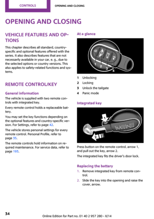 38
38 39
39 40
40 41
41 42
42 43
43 44
44 45
45 46
46 47
47 48
48 49
49 50
50 51
51 52
52 53
53 54
54 55
55 56
56 57
57 58
58 59
59 60
60 61
61 62
62 63
63 64
64 65
65 66
66 67
67 68
68 69
69 70
70 71
71 72
72 73
73 74
74 75
75 76
76 77
77 78
78 79
79 80
80 81
81 82
82 83
83 84
84 85
85 86
86 87
87 88
88 89
89 90
90 91
91 92
92 93
93 94
94 95
95 96
96 97
97 98
98 99
99 100
100 101
101 102
102 103
103 104
104 105
105 106
106 107
107 108
108 109
109 110
110 111
111 112
112 113
113 114
114 115
115 116
116 117
117 118
118 119
119 120
120 121
121 122
122 123
123 124
124 125
125 126
126 127
127 128
128 129
129 130
130 131
131 132
132 133
133 134
134 135
135 136
136 137
137 138
138 139
139 140
140 141
141 142
142 143
143 144
144 145
145 146
146 147
147 148
148 149
149 150
150 151
151 152
152 153
153 154
154 155
155 156
156 157
157 158
158 159
159 160
160 161
161 162
162 163
163 164
164 165
165 166
166 167
167 168
168 169
169 170
170 171
171 172
172 173
173 174
174 175
175 176
176 177
177 178
178 179
179 180
180 181
181 182
182 183
183 184
184 185
185 186
186 187
187 188
188 189
189 190
190 191
191 192
192 193
193 194
194 195
195 196
196 197
197 198
198 199
199 200
200 201
201 202
202 203
203 204
204 205
205 206
206 207
207 208
208 209
209 210
210 211
211 212
212 213
213 214
214 215
215 216
216 217
217 218
218 219
219 220
220 221
221 222
222 223
223 224
224 225
225 226
226 227
227 228
228 229
229 230
230 231
231 232
232 233
233 234
234 235
235 236
236 237
237 238
238 239
239