2014 MERCEDES-BENZ S-CLASS COUPE remote control
[x] Cancel search: remote controlPage 155 of 413
X
Press the uand^ buttons simulta-
neously.
The Îsymbol in the remote control dis-
play flashes.
X Press the ,or. button to set the
desired departure time.
i The longer you press the
,or.
button, the faster the time changes.
X Press the uand^ buttons simulta-
neously.
The new departure time is stored.
When setting the departure time, observe the important safety notes (Y page 148).
Activating the set departure time X Briefly press the ubutton.
X Press the ,or. button repeatedly
until the desired departure time appears in
the display.
X Press the ubutton.
The Ísymbol, the departure time and,
depending on the selected departure time, the letter A, BorCappear in the display.
Deactivating the set departure time
X Briefly press the ubutton.
X Press the ,or. button.
The status of the auxiliary heating is shown in the display.
X Press the .button.
The first departure time stored appears in
the display.
X Press the ^button.
OFF
OFF is shown in the remote control display.
Switching the heater booster function
on/off The heater booster function helps the engine
reach its operating temperature faster during
its warm-up phase. This helps to heat the
vehicle interior faster. The heater booster
function switches on at lower outside tem-
peratures and lower coolant temperatures.
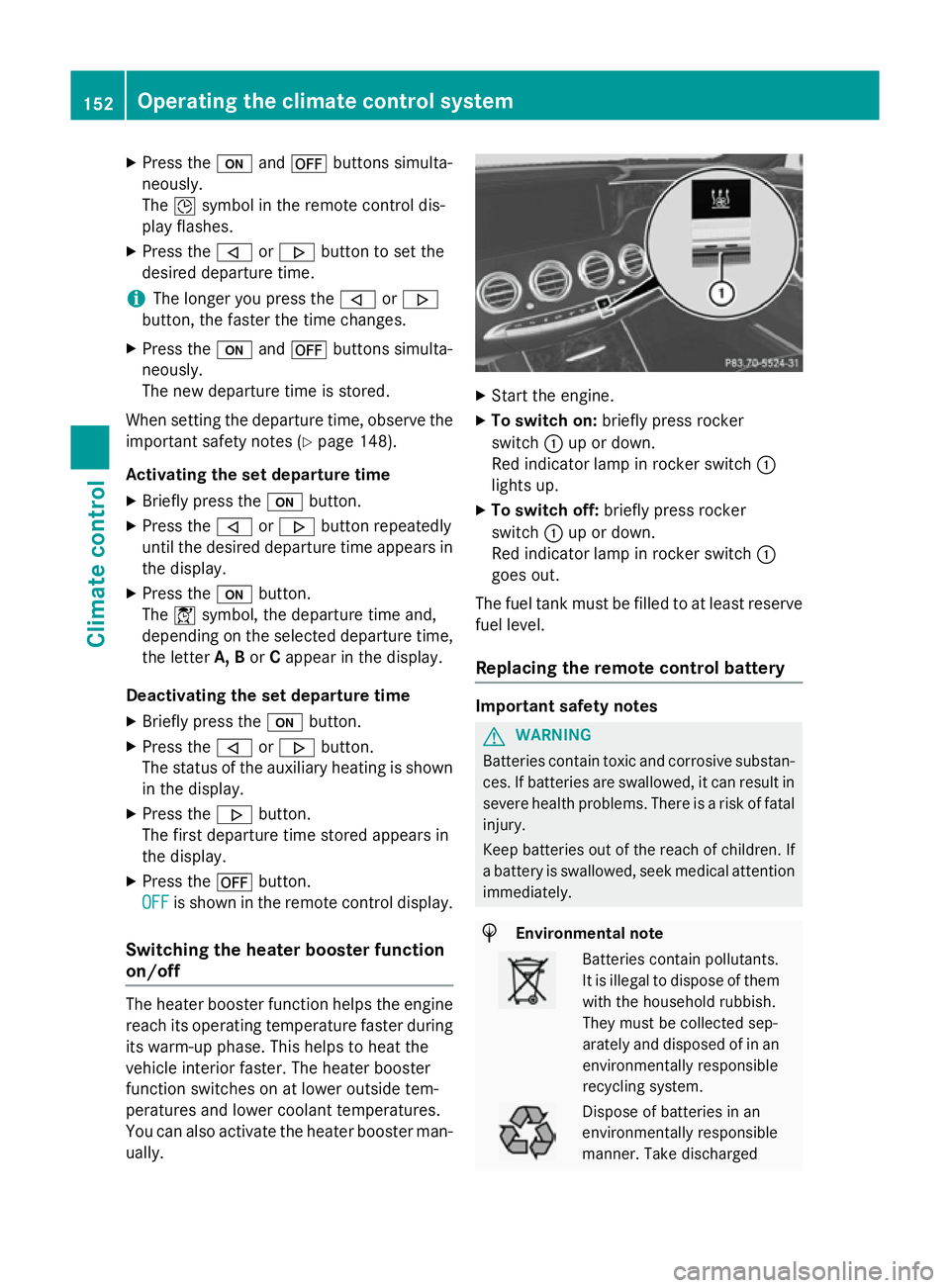
You can also activate the heater booster man- ually. X
Start the engine.
X To switch on: briefly press rocker
switch :up or down.
Red indicator lamp in rocker switch :
lights up.
X To switch off: briefly press rocker
switch :up or down.
Red indicator lamp in rocker switch :
goes out.
The fuel tank must be filled to at least reserve fuel level.
Replacing the remote control battery Important safety notes
G
WARNING
Batteries contain toxic and corrosive substan- ces. If batteries are swallowed, it can result in
severe health problems. There is a risk of fatal injury.
Keep batteries out of the reach of children. If
a battery is swallowed, seek medical attention immediately. H
Environmental note Batteries contain pollutants.
It is illegal to dispose of them
with the household rubbish.
They must be collected sep-
arately and disposed of in anenvironmentally responsible
recycling system. Dispose of batteries in an
environmentally responsible
manner. Take discharged152
Operating the climate control systemClimate control
Page 156 of 413
batteries to a qualified spe-
cialist workshop or to a col-
lection point for used batter-
ies.
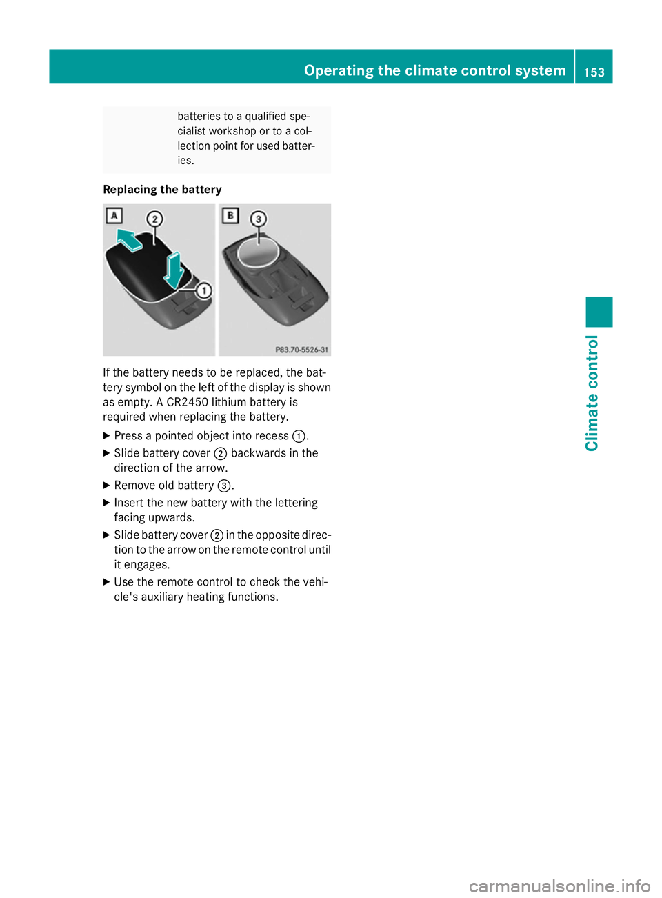
Replacing the battery If the battery needs to be replaced, the bat-
tery symbol on the left of the display is shown as empty. A CR2450 lithium battery is
required when replacing the battery.
X Press a pointed object into recess :.
X Slide battery cover ;backwards in the
direction of the arrow.
X Remove old battery =.
X Insert the new battery with the lettering
facing upwards.
X Slide battery cover ;in the opposite direc-
tion to the arrow on the remote control until
it engages.
X Use the remote control to check the vehi-
cle's auxiliary heating functions. Operating the climate control system
153Climate control Z
Page 157 of 413
Problems with the auxiliary heating/ventilation
Display messages
Possible causes/consequences and
M
MSolutions FAIL¨ The signal transmission between the transmitter and the vehicle is
faulty.
X Change your position in relation to the vehicle, moving closer if
necessary.
X Make another attempt to switch the auxiliary heating/ventila-
tion on or off using the remote control. FAIL The auxiliary heating cannot be switched on or has switched itself
off.
The starter battery is not sufficiently charged.
X Charge the starter battery.
X Make another attempt to switch on the auxiliary heating/venti-
lation using the remote control. The auxiliary heating cannot be switched on or has switched itself
off.
The fuel tank content is below the reserve fuel level.
X Refuel at the nearest filling station.
X Make another attempt to switch on the auxiliary heating using
the remote control. FAIL¯ The auxiliary heating/ventilation cannot be switched on or has
switched itself off during operation.
The auxiliary heating/ventilation is faulty.
X Have the auxiliary heating/ventilation checked at a qualified
specialist workshop. Adjusting the air vents
Important safety notes
G
WARNING
Very hot or very cold air can flow from the air vents. This could result in burns or frostbite in the immediate vicinity of the air vents. There
is a risk of injury.
Make sure that all vehicle occupants always
maintain a sufficient distance to the air out-
lets. If necessary, redirect the airflow to
another area of the vehicle interior. In order to ensure the direct flow of fresh air
through the air vents into the vehicle interior,
please observe the following notes:
R keep the air inlet between the windscreen
and the bonnet free of blockages, such as
ice, snow or leaves.
R never cover the vents or ventilation grilles
in the vehicle interior. 154
Adjusting the air ventsClimate control
Page 163 of 413
If you depress the brake pedal and press the
Start/Stop button, the engine starts immedi-
ately.
A check which periodically establishes a radio
connection between the vehicle and the key
determines whether a valid key is in the vehi- cle. This occurs, for example, when starting
the engine.
To start the vehicle without actively using the
key:
R the Start/Stop button must be inserted in
the ignition lock
R the key must be in the vehicle
R the vehicle must not be locked with the key
or KEYLESS-GO (Y page 85)
Do not keep the key:
R with electronic devices, e.g. a mobile
phone or another key
R with metallic objects, e.g. coins or metal
film
R inside metallic objects, e.g. a metal case
This can affect the key's functionality.
If you lock the vehicle with the key's remote
control or with KEYLESS-GO, after a short
time:
R you will not be able to switch on the ignition
with the Start/Stop button
R you will not be able to start the engine with
the Start/Stop button until the vehicle is
unlocked again
If you lock the vehicle centrally using the but- ton on the front door (Y page 91), you can
continue to start the engine with the Start/
Stop button.
The engine can be switched off while the vehi-
cle is in motion by pressing and holding the
Start/Stop button for three seconds. This
function operates independently of the ECO
start/stop automatic engine switch-off func-
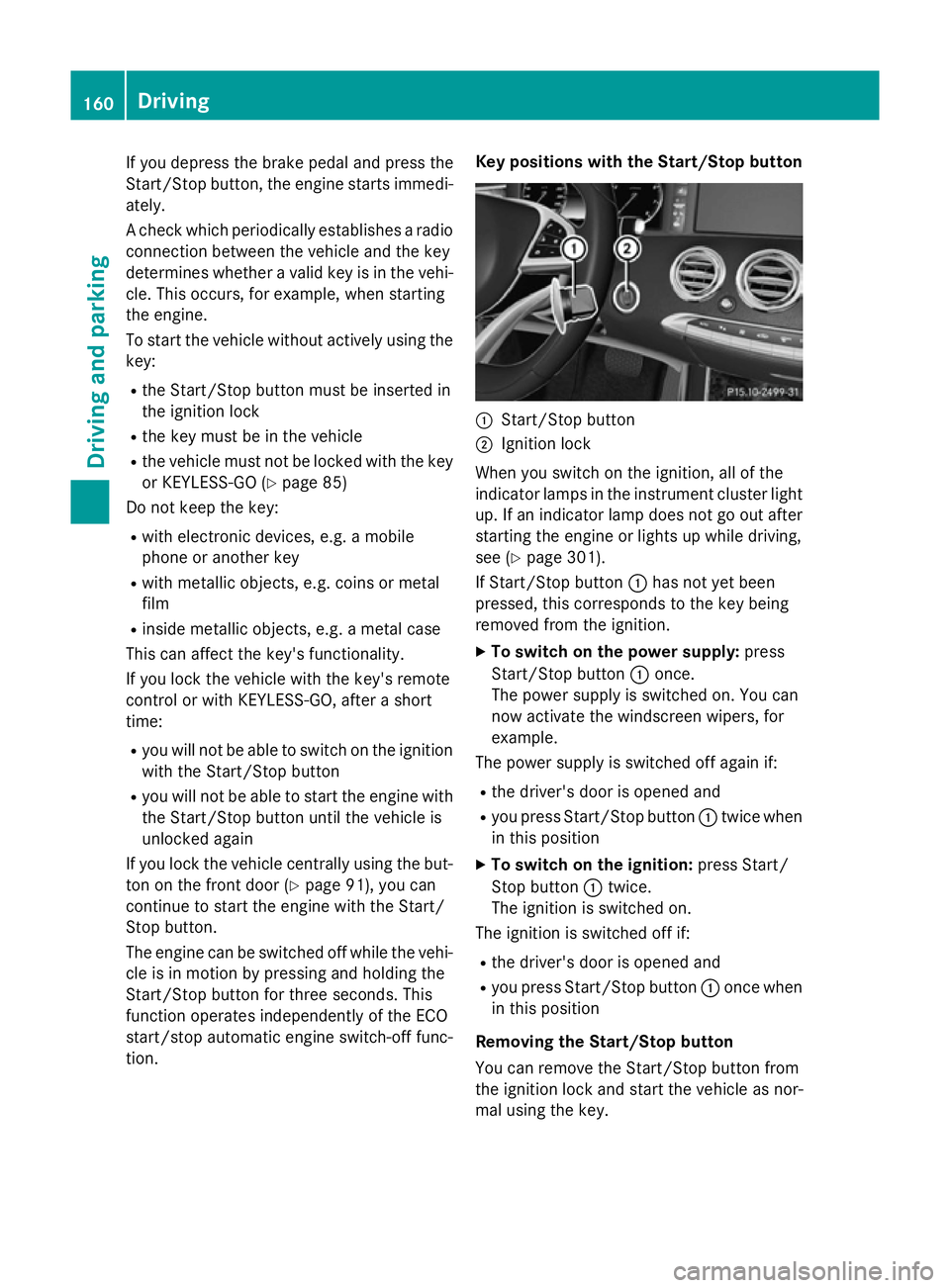
tion. Key positions with the Start/Stop button
:
Start/Stop button
; Ignition lock
When you switch on the ignition, all of the
indicator lamps in the instrument cluster light up. If an indicator lamp does not go out after
starting the engine or lights up while driving,
see (Y page 301).
If Start/Stop button :has not yet been
pressed, this corresponds to the key being
removed from the ignition.
X To switch on the power supply: press
Start/Stop button :once.
The power supply is switched on. You can
now activate the windscreen wipers, for
example.
The power supply is switched off again if:
R the driver's door is opened and
R you press Start/Stop button :twice when
in this position
X To switch on the ignition: press Start/
Stop button :twice.
The ignition is switched on.
The ignition is switched off if:
R the driver's door is opened and
R you press Start/Stop button :once when
in this position
Removing the Start/Stop button
You can remove the Start/Stop button from
the ignition lock and start the vehicle as nor-
mal using the key. 160
DrivingDriving and parking
Page 318 of 413
R
Close lockable stowage compartments
while driving.
R Stow and secure objects that are heavy,
hard, pointy, sharp-edged, fragile or too
large in the boot.
Observe the loading guidelines (Y page 314).
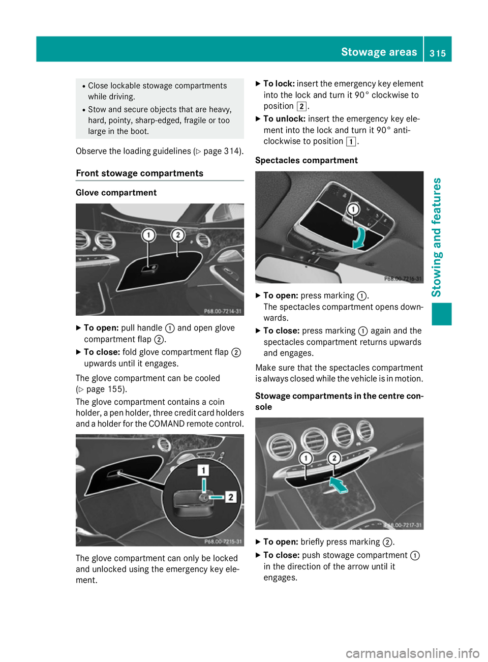
Front stowage compartments Glove compartment
X
To open: pull handle :and open glove
compartment flap ;.
X To close: fold glove compartment flap ;
upwards until it engages.
The glove compartment can be cooled
(Y page 155).
The glove compartment contains a coin
holder, a pen holder, three credit card holders
and a holder for the COMAND remote control. The glove compartment can only be locked
and unlocked using the emergency key ele-
ment. X
To lock: insert the emergency key element
into the lock and turn it 90° clockwise to
position 2.
X To unlock: insert the emergency key ele-
ment into the lock and turn it 90° anti-
clockwise to position 1.
Spectacles compartment X
To open: press marking :.
The spectacles compartment opens down- wards.
X To close: press marking :again and the
spectacles compartment returns upwards
and engages.
Make sure that the spectacles compartment
is always closed while the vehicle is in motion.
Stowage compartments in the centre con-
sole X
To open: briefly press marking ;.
X To close: push stowage compartment :
in the direction of the arrow until it
engages. Stowage areas
315Stowing and features Z
Page 331 of 413
Garage door opener
General notes The HomeLink
®
garage door opener integra-
ted in the rear-view mirror allows you to oper- ate up to three different door and gate sys-
tems.
Once programmed, the integrated garage
door opener in the rear-view mirror will
assume the function of the garage door sys-
tem's remote control. Please also read the
operating instructions for the garage door
system.
When programming a garage door opener,
park the vehicle outside the garage. Do not
run the engine while programming.
The garage door opener is only available for
certain countries. Observe the legal require-
ments for each individual country.
The HomeLink ®
garage door opener is com-
patible with most European garage and gate
opener drives. More information on Home-
Link ®
and/or compatible products is availa-
ble:
R at a qualified specialised workshop
R via the HomeLink ®
Hotline
(0) 08000 466 354 65 or alternatively
+49 (0) 6838 907-277
R on the Internet at
http://www.homelink.com
Important safety notes G
WARNING
When you operate or program the garage door with the integrated garage door opener, per-
sons in the range of movement of the garage
door can become trapped or struck by the
garage door. There is a risk of injury.
When using the integrated garage door
opener, always make sure that nobody is
within the range of movement of the garage
door. G
WARNING
Combustion engines emit poisonous exhaust
gases such as carbon monoxide. Inhaling
these exhaust gases leads to poisoning. There is a risk of fatal injury. Therefore never leave
the engine running in enclosed spaces with-
out sufficient ventilation.
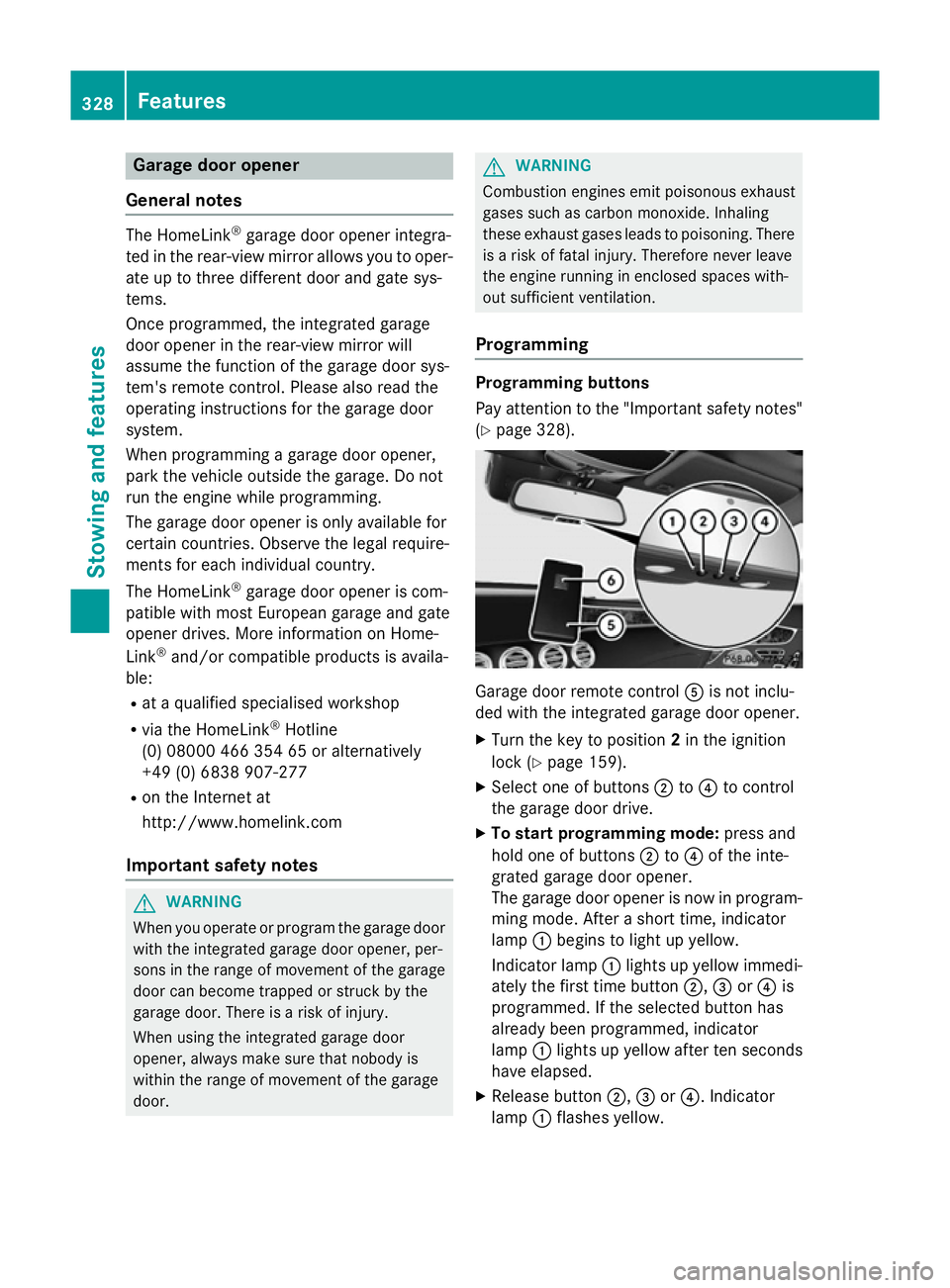
Programming Programming buttons
Pay attention to the "Important safety notes"
(Y page 328). Garage door remote control
Ais not inclu-
ded with the integrated garage door opener.
X Turn the key to position 2in the ignition
lock (Y page 159).
X Select one of buttons ;to? to control
the garage door drive.
X To start programming mode: press and
hold one of buttons ;to? of the inte-
grated garage door opener.
The garage door opener is now in program- ming mode. After a short time, indicator
lamp :begins to light up yellow.
Indicator lamp :lights up yellow immedi-
ately the first time button ;,=or? is
programmed. If the selected button has
already been programmed, indicator
lamp :lights up yellow after ten seconds
have elapsed.
X Release button ;,=or?. Indicator
lamp :flashes yellow. 328
FeaturesStowing and features
Page 332 of 413
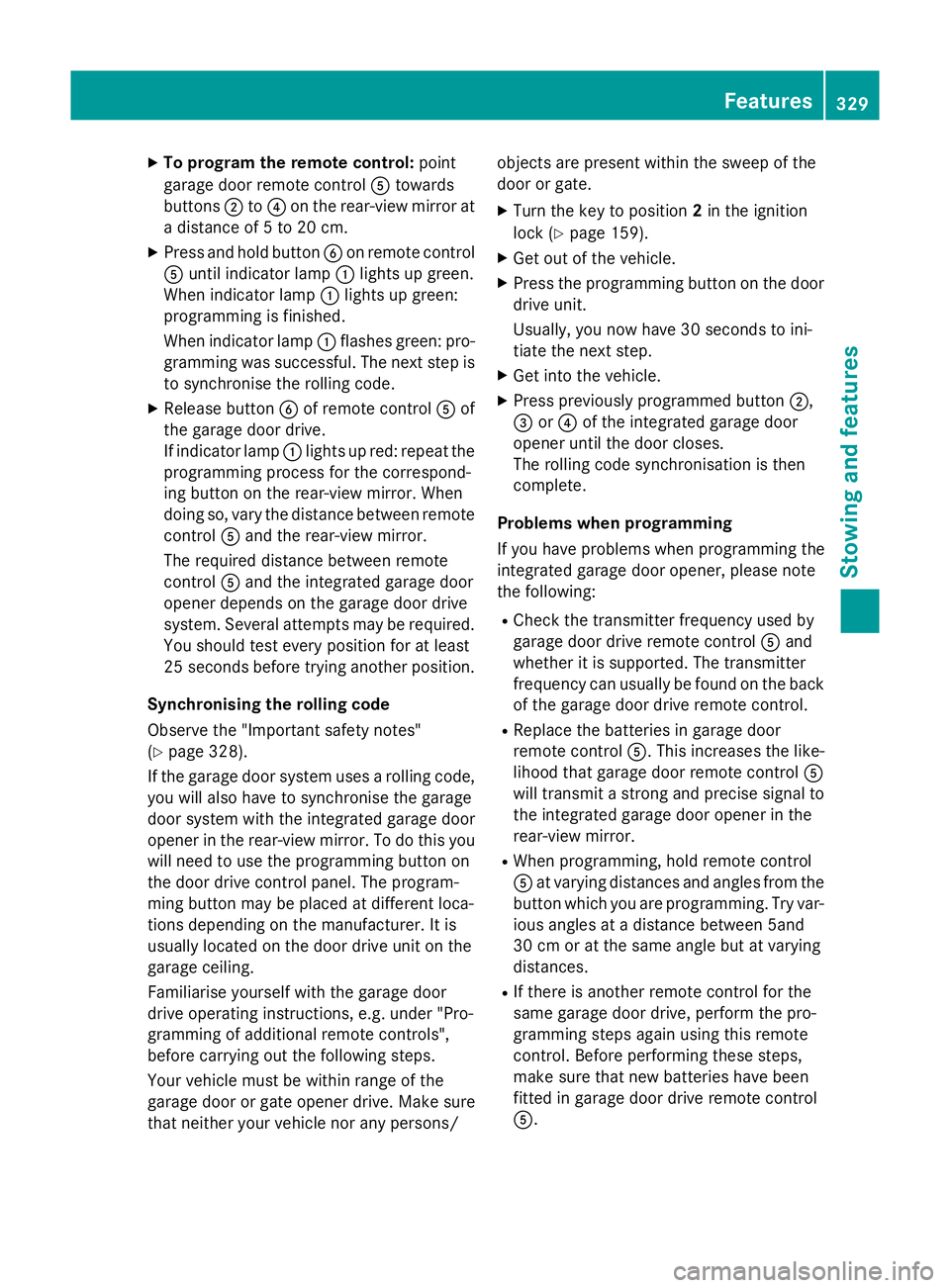
X
To program the remote control: point
garage door remote control Atowards
buttons ;to? on the rear-view mirror at
a distance of 5 to 20 cm.
X Press and hold button Bon remote control
A until indicator lamp :lights up green.
When indicator lamp :lights up green:
programming is finished.
When indicator lamp :flashes green: pro-
gramming was successful. The next step is
to synchronise the rolling code.
X Release button Bof remote control Aof
the garage door drive.
If indicator lamp :lights up red: repeat the
programming process for the correspond-
ing button on the rear-view mirror. When
doing so, vary the distance between remote control Aand the rear-view mirror.
The required distance between remote
control Aand the integrated garage door
opener depends on the garage door drive
system. Several attempts may be required.
You should test every position for at least
25 second sbefore trying another position.
Synchronising the rolling code
Observe the "Important safety notes"
(Y page 328).
If the garage door system uses a rolling code,
you will also have to synchronise the garage
door system with the integrated garage door
opener in the rear-view mirror. To do this you
will need to use the programming button on
the door drive control panel. The program-
ming button may be placed at different loca-
tions depending on the manufacturer. It is
usually located on the door drive unit on the
garage ceiling.
Familiarise yourself with the garage door
drive operating instructions, e.g. under "Pro-
gramming of additional remote controls",
before carrying out the following steps.
Your vehicle must be within range of the
garage door or gate opener drive. Make sure
that neither your vehicle nor any persons/ objects are present within the sweep of the
door or gate.
X Turn the key to position 2in the ignition
lock (Y page 159).
X Get out of the vehicle.
X Press the programming button on the door
drive unit.
Usually, you now have 30 seconds to ini-
tiate the next step.
X Get into the vehicle.
X Press previously programmed button ;,
= or? of the integrated garage door
opener until the door closes.
The rolling code synchronisation is then
complete.
Problems when programming
If you have problems when programming the
integrated garage door opener, please note
the following: R Check the transmitter frequency used by
garage door drive remote control Aand
whether it is supported. The transmitter
frequency can usually be found on the back
of the garage door drive remote control.
R Replace the batteries in garage door
remote control A. This increases the like-
lihood that garage door remote control A
will transmit a strong and precise signal to the integrated garage door opener in the
rear-view mirror.
R When programming, hold remote control
A at varying distances and angles from the
button which you are programming. Try var- ious angles at a distance between 5and
30 cm or at the same angle but at varying
distances.
R If there is another remote control for the
same garage door drive, perform the pro-
gramming steps again using this remote
control. Before performing these steps,
make sure that new batteries have been
fitted in garage door drive remote control
A. Features
329Stowing and features Z
Page 333 of 413
R
Note that some remote controls transmit
only for a limited period (the indicator lamp
on the remote control goes out). Press but-ton Bon remote control Aagain before
transmission ends.
R Align the aerial cable of the garage door
opener unit. This can improve signal recep-
tion/transmission.
Opening or closing the garage door Once programmed, the integrated garage
door opener will assume the function of the
garage door system's remote control. Please
also read the operating instructions for the
garage door system.
X Turn the key to position 2in the ignition
lock (Y page 159).
X Press button ;,=or? which you have
programmed to operate the garage door.
Garage door system with a fixed code: indi-
cator lamp :lights up green.
Garage door system with a rolling code:
indicator lamp :flashes green.
The transmitter will transmit a signal for as
long as the button is pressed. The transmis-
sion is halted after a maximum of ten seconds and indicator lamp :lights up yellow. Press
button ;,=or? again if necessary.
Clearing the memory Make sure that you clear the memory of the
integrated garage door opener before selling
the vehicle.
X Turn the key to position 2in the ignition
lock (Y page 159).
X Press and hold buttons ;and ?.
The indicator lamp initially lights up yellow
and then green.
X Release buttons ;and ?.
The memory of the integrated garage door
opener in the rear-view mirror is cleared. Frequencies Europe
Country Radio type approval num-
ber
Frequency range (MHz)
AD (Andorra) 20 July 2005
MHz: 27, 30, 40, 433, 868
AT (Austria) Article 6 of Directive
1999/5/EC R&TTE 18 May
05
MHz: 27, 40, 433, 868
BE (Belgium) Article 6 of Directive
1999/5/EC R&TTE 18 May
05
MHz: 27, 40, 433, 868
BG (Bulga-
ria) Article 6 of Directive
1999/5/EC R&TTE 12 April
07
MHz: 27, 40, 433, 868 CH (Switzer-
land) Article 6 of Directive
1999/5/EC R&TTE 14357
27 May 05
MHz: 27, 40, 433, 868
CY (Cyprus) Article 6 of Directive
1999/5/EC R&TTE 5 May
05
MHz: 27, 40, 433, 868
CZ (Czech
Republic) General Licence GL-30/R/
2000 Reg No. 844 13 May
05
MHz: 27, 40, 433
DK (Den-
mark) Article 6 of Directive
1999/5/EC R&TTE 20 April
05
MHz: 27, 40, 433, 868 DE (Ger-
many) Article 6 of Directive
1999/5/EC R&TTE
7519301 29 April 05
MHz: 27, 40, 433, 868330
FeaturesStowing and features