Page 372 of 413

Fitting/removing the towing eye
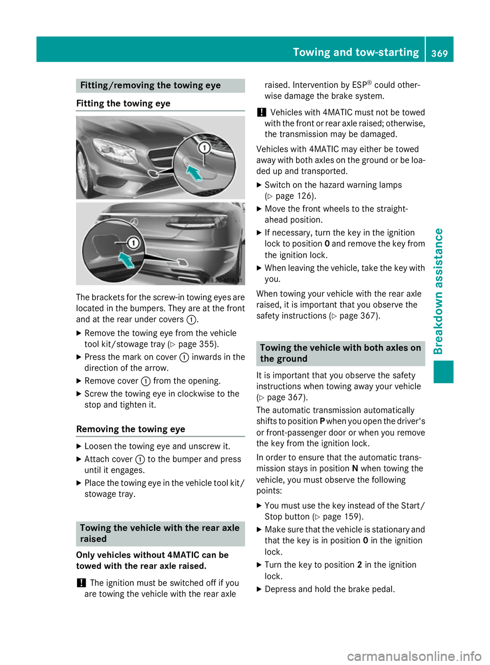
Fitting the towing eye The brackets for the screw-in towing eyes are
located in the bumpers. They are at the front and at the rear under covers :.
X Remove the towing eye from the vehicle
tool kit/stowage tray (Y page 355).
X Press the mark on cover :inwards in the
direction of the arrow.
X Remove cover :from the opening.
X Screw the towing eye in clockwise to the
stop and tighten it.
Removing the towing eye X
Loosen the towing eye and unscrew it.
X Attach cover :to the bumper and press
until it engages.
X Place the towing eye in the vehicle tool kit/
stowage tray. Towing the vehicle with the rear axle
raised
Only vehicles without 4MATIC can be
towed with the rear axle raised.
! The ignition must be switched off if you
are towing the vehicle with the rear axle raised. Intervention by ESP
®
could other-
wise damage the brake system.
! Vehicles with 4MATIC must not be towed
with the front or rear axle raised; otherwise,
the transmission may be damaged.
Vehicles with 4MATIC may either be towed
away with both axles on the ground or be loa- ded up and transported.
X Switch on the hazard warning lamps
(Y page 126).
X Move the front wheels to the straight-
ahead position.
X If necessary, turn the key in the ignition
lock to position 0and remove the key from
the ignition lock.
X When leaving the vehicle, take the key with
you.
When towing your vehicle with the rear axle
raised, it is important that you observe the
safety instructions (Y page 367). Towing the vehicle with both axles on
the ground
It is important that you observe the safety
instructions when towing away your vehicle
(Y page 367).
The automatic transmission automatically
shifts to position Pwhen you open the driver's
or front-passenger door or when you remove the key from the ignition lock.
In order to ensure that the automatic trans-
mission stays in position Nwhen towing the
vehicle, you must observe the following
points:
X You must use the key instead of the Start/
Stop button (Y page 159).
X Make sure that the vehicle is stationary and
that the key is in position 0in the ignition
lock.
X Turn the key to position 2in the ignition
lock.
X Depress and hold the brake pedal. Towing and tow-starting
369Breakdown assistance Z
Page 373 of 413

X
Shift the automatic transmission to posi-
tion N.
X Release the brake pedal.
X Release the electric parking brake.
X Leave the key in position 2in the ignition
lock.
X Switch on the hazard warning lamps
(Y page 126).
i In order to signal a change of direction
when towing the vehicle with the hazard
warning lamps switched on, use the com-
bination switch as usual. In this case, only
the turn signals for the desired direction
flash. When you reset the combination
switch, the hazard warning lamps start
flashing again. Transporting the vehicle
! You may only secure the vehicle by the
wheels, not by parts of the vehicle such as
axle or steering components. Otherwise,
the vehicle could be damaged.
The towing eye can be used to pull the vehicle
onto a trailer or transporter for transporta-
tion.
X Turn the key to position 2in the ignition
lock.
X Shift the automatic transmission to posi-
tion N.
As soon as the vehicle is loaded: X Prevent the vehicle from rolling away by
applying the electric parking brake.
X Shift the automatic transmission to posi-
tion P.
X Turn the key to position 0in the ignition
lock and remove it.
X Secure the vehicle. Notes for 4MATIC vehicles
! Vehicles with 4MATIC must not be towed
with the front or rear axle raised; otherwise,
the transmission may be damaged.
Vehicles with 4MATIC may either be towed
away with both axles on the ground or be loa- ded up and transported.
If the vehicle has transmission damage or
damage to the front or rear axle, have it trans-
ported on a transporter or trailer.
In the event of damage to the electrical
system: if the battery is defective, the auto-
matic transmission will be locked in position
P. To shift the automatic transmission to posi-
tion N, you must provide power to the vehi-
cle's electrical system in the same way as
when jump-starting (Y page 364).
Have the vehicle transported on a transporter
or trailer. Tow-starting (emergency engine
starting)
! Do not tow-start vehicles with automatic
transmission. You could otherwise damage the automatic transmission.
i Information on "Jump-starting"
(Y page 364). Electrical fuses
Important safety notes
G
WARNING
If you manipulate, bridge or replace a faulty
fuse with a fuse of a higher amperage, the
electric cables could be overloaded. This may result in a fire. There is a risk of an accident
and injury.
Always replace faulty fuses with specified new fuses of the correct amperage.
Blown fuses must be replaced with fuses of
the same rating, which you can recognise by 370
Electrical fusesBreakdown assistance
Page 394 of 413

X
Clean the wheel and wheel hub contact
surfaces.
X Slide the wheel to be mounted onto the
centring pin and push it on.
X Tighten the wheel bolts until they are fin-
ger-tight.
X Unscrew the centring pin.
X Tighten the last wheel bolt until it is finger-
tight.
Lowering the vehicle G
WARNING
The wheels could work loose if the wheel nuts and bolts are not tightened to the specified
tightening torque. There is a risk of accident.
Have the tightening torque immediately
checked at a qualified specialist workshop
after a wheel is changed. X
Place the ratchet ring spanner onto the
hexagon nut of the jack so that the letters
AB are visible.
X Turn the ratchet ring spanner until the vehi-
cle is once again standing firmly on the
ground.
X Place the jack to one side.
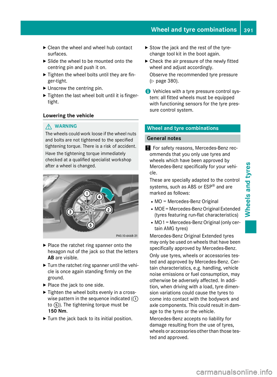
X Tighten the wheel bolts evenly in a cross-
wise pattern in the sequence indicated ( :
to A). The tightening torque must be
150 Nm .
X Turn the jack back to its initial position. X
Stow the jack and the rest of the tyre-
change tool kit in the boot again.
X Check the air pressure of the newly fitted
wheel and adjust accordingly.
Observe the recommended tyre pressure
(Y page 380).
i Vehicles with a tyre pressure control sys-
tem: all fitted wheels must be equipped
with functioning sensors for the tyre pres-
sure control system. Wheel and tyre combinations
General notes
! For safety reasons, Mercedes-Benz rec-
ommends that you only use tyres and
wheels which have been approved by
Mercedes-Benz specifically for your vehi-
cle.
These are specially adapted to the control
systems, such as ABS or ESP ®
and are
marked as follows:
R MO = Mercedes-Benz Original
R MOE = Mercedes-Benz Original Extended
(tyres featuring run-flat characteristics)
R MO1 = Mercedes-Benz Original (only cer-
tain AMG tyres)
Mercedes-Benz Original Extended tyres
may only be used on wheels that have been
specifically approved by Mercedes-Benz.
Only use tyres, wheels or accessories tes-
ted and approved by Mercedes-Benz. Cer-
tain characteristics, e.g. handling, vehicle
noise emissions or fuel consumption, may
otherwise be adversely affected. In addi-
tion, when driving with a load, tyre dimen-
sion variations could cause the tyres to
come into contact with the bodywork and
axle components. This could result in dam- age to the tyres or the vehicle.
Mercedes-Benz accepts no liability for
damage resulting from the use of tyres,
wheels or accessories other than those tes- ted and approved. Wheel and tyre combinations
391Wheels and tyres Z