2014 MERCEDES-BENZ CLS COUPE service
[x] Cancel search: servicePage 254 of 417
X
Press the abutton.
The current selection is displayed.
X To activate/deactivate: press thea
button again.
If the Blind Spot Assist Sensors deac‐
Blind Spot Assist Sensors deac‐
tivated
tivated orAct. B. Spot Assist Sen‐
Act. B. Spot Assist Sen‐
sors deactivated
sors deactivated message appears, the
radar sensor system is deactivated.
X Switch on the radar sensor system
(Y page 255).
Further information about Blind Spot Assist
(Y page 223).
Further information about Active Blind Spot
Assist (Y page 227).
Activating/deactivating Lane Keeping
Assist X
Press the =or; button on the steer-
ing wheel to select the Assist. Assist.menu.
X Press the 9or: button to select
Lane Keep. Assist
Lane Keep. Assist
X Press the abutton.
The current selection is displayed.
X Press ato confirm.
X Press the :or9 button to set Off
Off,
Standard
Standard orAdaptive
Adaptive.
X Press the abutton to save the setting.
When Lane Keeping Assist or Active Lane
Keeping Assist is activated, the multifunc-
tion display shows the lane markings as
bright lines in the assistance graphic.
For further information about Lane Keeping
Assist, see (Y page 225).
For further information about Active Lane
Keeping Assist, see (Y page 229). Service menu
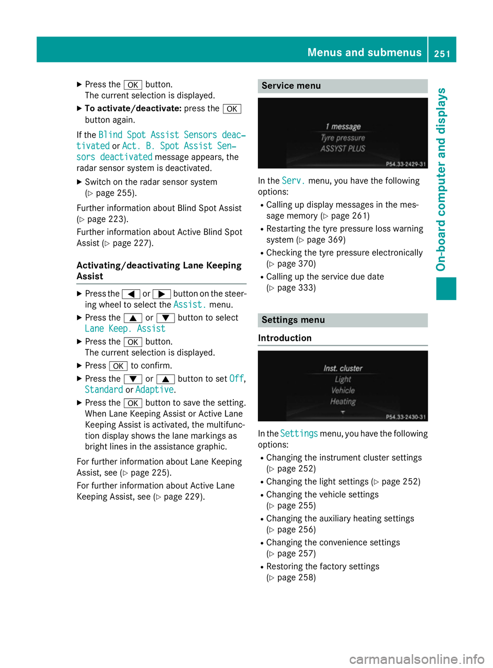
In the
Serv. Serv. menu, you have the following
options:
R Calling up display messages in the mes-
sage memory (Y page 261)
R Restarting the tyre pressure loss warning
system (Y page 369)
R Checking the tyre pressure electronically
(Y page 370)
R Calling up the service due date
(Y page 333) Settings menu
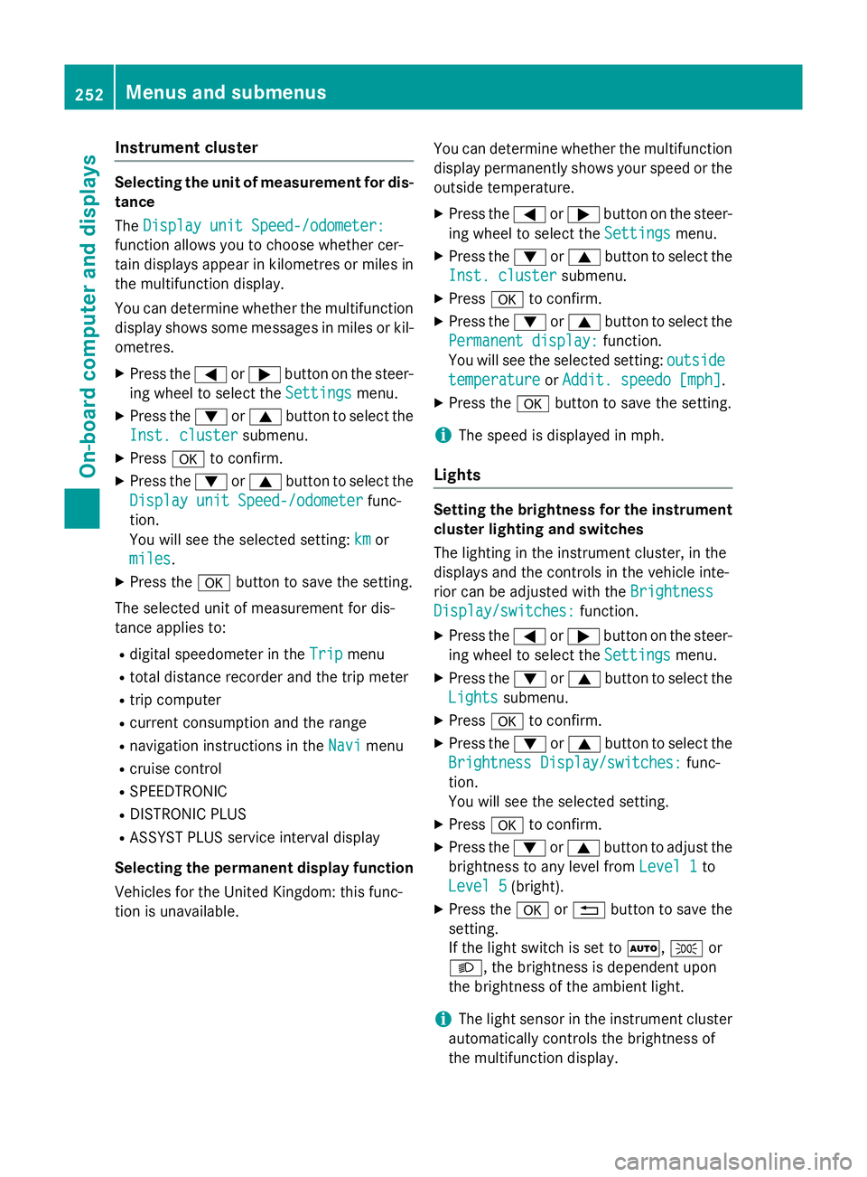
Introduction In the
Settings Settings menu, you have the following
options:
R Changing the instrument cluster settings
(Y page 252)
R Changing the light settings (Y page 252)
R Changing the vehicle settings
(Y page 255)
R Changing the auxiliary heating settings
(Y page 256)
R Changing the convenience settings
(Y page 257)
R Restoring the factory settings
(Y page 258) Menus and submenus
251On-board computer and displays Z
Page 255 of 417
Instrument cluster
Selecting the unit of measurement for dis-
tance
The Display unit Speed-/odometer: Display unit Speed-/odometer:
function allows you to choose whether cer-
tain displays appear in kilometres or miles in the multifunction display.
You can determine whether the multifunction display shows some messages in miles or kil-
ometres.
X Press the =or; button on the steer-
ing wheel to select the Settings
Settings menu.
X Press the :or9 button to select the
Inst. cluster
Inst. cluster submenu.
X Press ato confirm.
X Press the :or9 button to select the
Display unit Speed-/odometer
Display unit Speed-/odometer func-
tion.
You will see the selected setting: km kmor
miles
miles.
X Press the abutton to save the setting.
The selected unit of measurement for dis-
tance applies to: R digital speedometer in the Trip Tripmenu
R total distance recorder and the trip meter
R trip computer
R current consumption and the range
R navigation instructions in the Navi
Navi menu
R cruise control
R SPEEDTRONIC
R DISTRONIC PLUS
R ASSYST PLUS service interval display
Selecting the permanent display function
Vehicles for the United Kingdom: this func-
tion is unavailable. You can determine whether the multifunction
display permanently shows your speed or the
outside temperature.
X Press the =or; button on the steer-
ing wheel to select the Settings Settingsmenu.
X Press the :or9 button to select the
Inst. cluster
Inst. cluster submenu.
X Press ato confirm.
X Press the :or9 button to select the
Permanent display:
Permanent display: function.
You will see the selected setting: outside
outside
temperature
temperature orAddit. speedo [mph]
Addit. speedo [mph].
X Press the abutton to save the setting.
i The speed is displayed in mph.
Lights Setting the brightness for the instrument
cluster lighting and switches
The lighting in the instrument cluster, in the
displays and the controls in the vehicle inte-
rior can be adjusted with the Brightness Brightness
Display/switches:
Display/switches: function.
X Press the =or; button on the steer-
ing wheel to select the Settings
Settingsmenu.
X Press the :or9 button to select the
Lights
Lights submenu.
X Press ato confirm.
X Press the :or9 button to select the
Brightness Display/switches:
Brightness Display/switches: func-
tion.
You will see the selected setting.
X Press ato confirm.
X Press the :or9 button to adjust the
brightness to any level from Level 1
Level 1 to
Level 5 Level 5 (bright).
X Press the aor% button to save the
setting.
If the light switch is set to Ã,Tor
L, the brightness is dependent upon
the brightness of the ambient light.
i The light sensor in the instrument cluster
automatically controls the brightness of
the multifunction display. 252
Menus and submenusOn-board computer and displays
Page 303 of 417
Useful information
i This Owner's Manual describes all mod-
els, series and optional equipment for your
vehicle that were available at the time of
going to press. National variations are pos- sible. Note that your vehicle may not be
equipped with all of the functions descri-
bed. This is also the case for systems and
functions relevant to safety.
i Read the information on qualified special-
ist workshops: (Y page 26). Stowage areas
Loading guidelines
G
WARNING
If objects, luggage or loads are not secured or not secured sufficiently, they could slip, tip
over or be flung around and thereby hit vehicle
occupants. There is a risk of injury, especially when braking or abruptly changing directions.
Always store objects so that they cannot be
flung around. Secure objects, luggage or
loads against slipping or tipping before the
journey. G
WARNING
Combustion engines emit poisonous exhaust
gases such as carbon monoxide. Exhaust
gases can enter the vehicle interior if the boot
lid/tailgate is open when the engine is run-
ning, especially if the vehicle is in motion.
There is a risk of poisoning.
Always switch off the engine before opening
the boot lid/tailgate. Never drive with the
boot lid/tailgate open. The handling characteristics of a laden vehi-
cle are dependent on the distribution of the
load within the vehicle. For this reason, you
should observe the following notes when
transporting a load:
R never exceed the maximum permissible
gross vehicle weight or the permissible axle
loads for the vehicle (including occupants).
R the boot/luggage compartment is the pre-
ferred place to store objects.
R position heavy loads as far forwards as pos-
sible and as low down in the boot/luggagecompartment as possible.
R the load must not protrude above the upper
edge of the seat backrests.
R always place the load against the rear or
front seat backrests. Make sure that the
seat backrests are securely locked into
place.
R always place the load behind unoccupied
seats if possible.
R use the lashing eyelets and the luggage
nets to transport loads and luggage.
R only use lashing eyelets and fastening com-
ponents that are suitable for the weight and
size of the load.
R when transporting objects in the luggage
compartment, the combined luggage cover
and net must always be installed (luggage
compartment cover and safety net).
R secure the load with sufficiently strong and
wear-resistant lashing material. Pad sharp
edges for protection.
i Load restraints are available at any quali-
fied specialist workshop, e.g. a Mercedes-
Benz Service Centre. Stowage spaces
Important safety notes G
WARNING
If objects in the passenger compartment are
stowed incorrectly, they can slide or be 300
Stowage areasStowing and features
Page 322 of 417

X
Briefly press cover ;at the top.
The cover opens.
X Lift up the cover of socket :.
Socket in the luggage compartment CLS Shooting Brake
X Lift up the cover of socket :.Mobile phone
Important safety notes G
WARNING
Operating mobile communications equip-
ment while driving distracts you from paying
attention to traffic conditions. This could also cause you to lose control of the vehicle. There
is a risk of an accident.
Use this device only when the vehicle is sta-
tionary.
i You must observe the legal requirements
for the country in which you are currently
driving when operating mobile communi-
cations equipment in the vehicle.
If it is permitted by law to operate commu-
nications equipment while the vehicle is in
motion, you may only do so if the traffic sit-
uation permits. You may otherwise be dis-
tracted from the traffic conditions, cause
an accident and injure yourself and others.
Excessive levels of electromagnetic radiation
may cause damage to your health and to the
health of others. The use of an exterior aerial takes into consideration the scientific discus-
sion surrounding the possible health risk
posed by electromagnetic fields.
Mercedes-Benz recommends the use of an
approved exterior aerial. This ensures:
R optimal mobile phone reception quality in
the vehicle
R that mutual interference between the vehi-
cle electronics and mobile phones is mini-
mised
An exterior aerial has the following advan-
tages:
R it conducts the electromagnetic fields gen-
erated by a wireless device to the exterior
R the field strength in the vehicle interior is
lower than in a vehicle that does not have
an exterior aerial
Information on retrofitting two-way radios
and mobile phones (RF transmitters)
(Y page 396).
General notes There are various mobile phone brackets that
may be fitted in your vehicle; in some cases,
these are country-specific.
You can connect a Bluetooth ®
-capable
mobile phone with Audio 20 or COMAND
Online via the Bluetooth ®
interface. This also
applies if your vehicle is equipped with con-
venience telephony.
More information on suitable mobile phones,
mobile phone brackets and on connecting
Bluetooth ®
-capable mobile phones with
Audio 20 or COMAND Online can be obtained:
R at your Mercedes-Benz Service Centre
R on the Internet at http://www.mercedes-
benz.com/connect
i The functions and services available when
you use the phone depend on your mobile
phone model and service provider. Features
319Stowing and features Z
Page 330 of 417
Useful information
............................328
Engine compartment ........................328
Service ............................................... 332
Care .................................................... 334 327Maintenance and care
Page 333 of 417
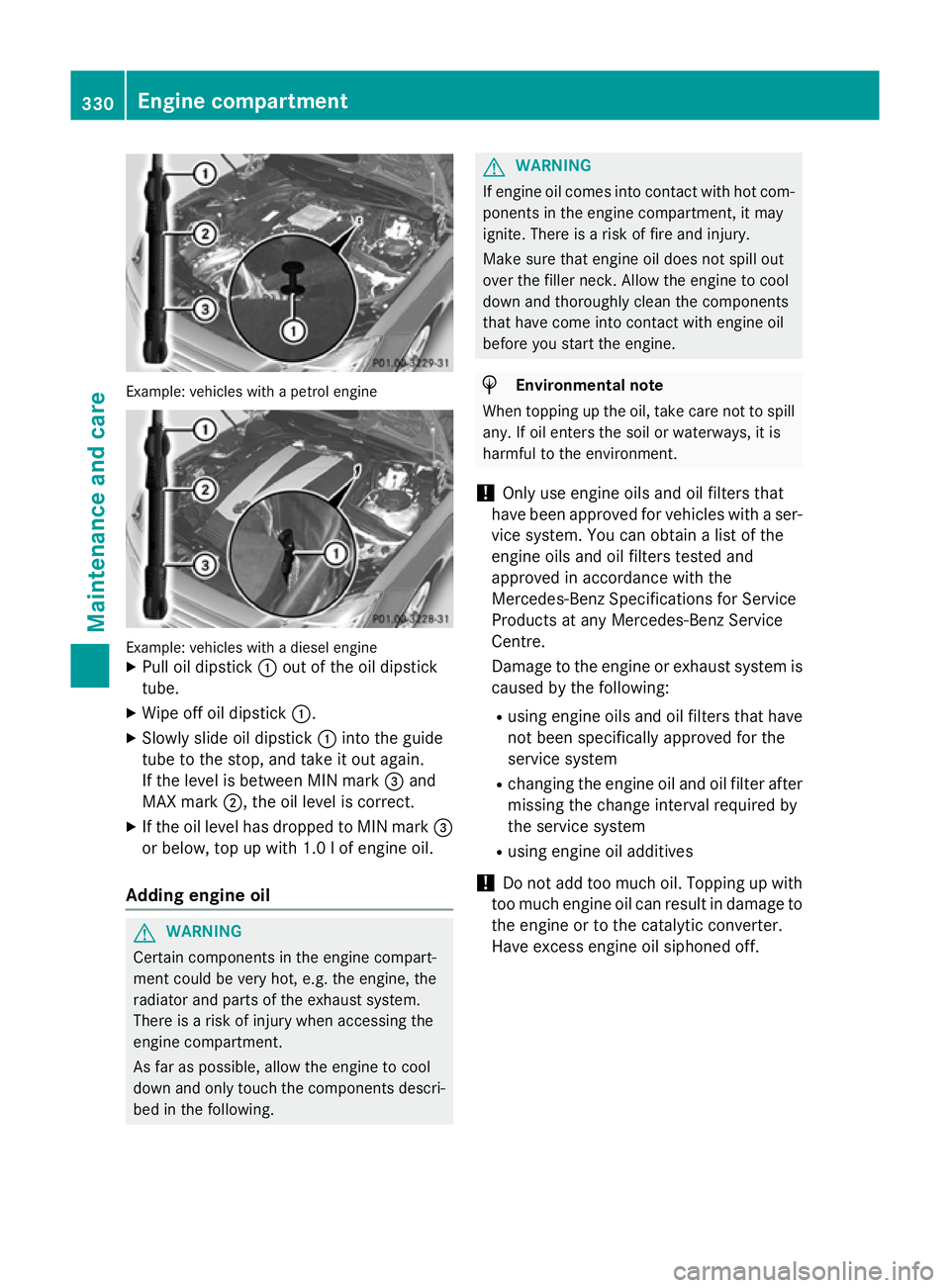
Example: vehicles with a petrol engine
Example: vehicles with a diesel engine
X Pull oil dipstick :out of the oil dipstick
tube.
X Wipe off oil dipstick :.
X Slowly slide oil dipstick :into the guide
tube to the stop, and take it out again.
If the level is between MIN mark =and
MAX mark ;, the oil level is correct.
X If the oil level has dropped to MIN mark =
or below, top up with 1.0 l of engine oil.
Adding engine oil G
WARNING
Certain components in the engine compart-
ment could be very hot, e.g. the engine, the
radiator and parts of the exhaust system.
There is a risk of injury when accessing the
engine compartment.
As far as possible, allow the engine to cool
down and only touch the components descri- bed in the following. G
WARNING
If engine oil comes into contact with hot com- ponents in the engine compartment, it may
ignite. There is a risk of fire and injury.
Make sure that engine oil does not spill out
over the filler neck. Allow the engine to cool
down and thoroughly clean the components
that have come into contact with engine oil
before you start the engine. H
Environmental note
When topping up the oil, take care not to spill
any. If oil enters the soil or waterways, it is
harmful to the environment.
! Only use engine oils and oil filters that
have been approved for vehicles with a ser-
vice system. You can obtain a list of the
engine oils and oil filters tested and
approved in accordance with the
Mercedes-Benz Specifications for Service
Products at any Mercedes-Benz Service
Centre.
Damage to the engine or exhaust system is caused by the following:
R using engine oils and oil filters that have
not been specifically approved for the
service system
R changing the engine oil and oil filter after
missing the change interval required by
the service system
R using engine oil additives
! Do not add too much oil. Topping up with
too much engine oil can result in damage to
the engine or to the catalytic converter.
Have excess engine oil siphoned off. 330
Engine compartmentMaintenance and care
Page 334 of 417
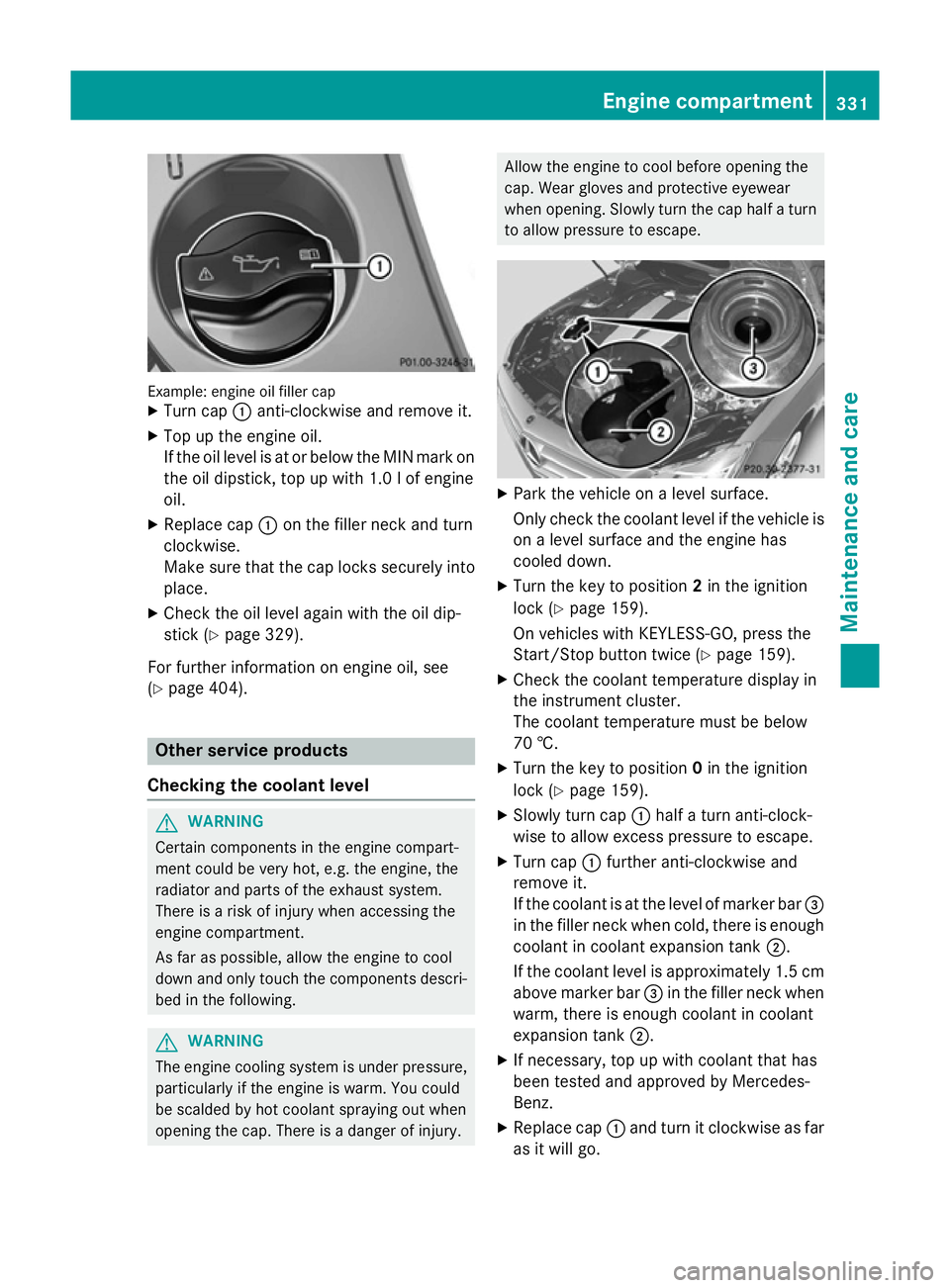
Example: engine oil filler cap
X Turn cap :anti-clockwise and remove it.
X Top up the engine oil.
If the oil level is at or below the MIN mark on
the oil dipstick, top up with 1.0 lof engine
oil.
X Replace cap :on the filler neck and turn
clockwise.
Make sure that the cap locks securely into place.
X Check the oil level again with the oil dip-
stick (Y page 329).
For further information on engine oil, see
(Y page 404). Other service products
Checking the coolant level G
WARNING
Certain components in the engine compart-
ment could be very hot, e.g. the engine, the
radiator and parts of the exhaust system.
There is a risk of injury when accessing the
engine compartment.
As far as possible, allow the engine to cool
down and only touch the components descri- bed in the following. G
WARNING
The engine cooling system is under pressure, particularly if the engine is warm. You could
be scalded by hot coolant spraying out when
opening the cap. There is a danger of injury. Allow the engine to cool before opening the
cap. Wear gloves and protective eyewear
when opening. Slowly turn the cap half a turn
to allow pressure to escape. X
Park the vehicle on a level surface.
Only check the coolant level if the vehicle is
on a level surface and the engine has
cooled down.
X Turn the key to position 2in the ignition
lock (Y page 159).
On vehicles with KEYLESS-GO, press the
Start/Stop button twice (Y page 159).
X Check the coolant temperature display in
the instrument cluster.
The coolant temperature must be below
70 †.
X Turn the key to position 0in the ignition
lock (Y page 159).
X Slowly turn cap :half a turn anti-clock-
wise to allow excess pressure to escape.
X Turn cap :further anti-clockwise and
remove it.
If the coolant is at the level of marker bar =
in the filler neck when cold, there is enough coolant in coolant expansion tank ;.
If the coolant level is approximately 1.5 cm above marker bar =in the filler neck when
warm, there is enough coolant in coolant
expansion tank ;.
X If necessary, top up with coolant that has
been tested and approved by Mercedes-
Benz.
X Replace cap :and turn it clockwise as far
as it will go. Engine compartment
331Maintenance and care Z
Page 335 of 417
For further information on coolant, see
(Y page 405).
Topping up the windscreen washer sys-
tem/headlamp cleaning system G
WARNING
Certain components in the engine compart-
ment could be very hot, e.g. the engine, the
radiator and parts of the exhaust system.
There is a risk of injury when accessing the
engine compartment.
As far as possible, allow the engine to cool
down and only touch the components descri- bed in the following. G
WARNING
If windscreen washer concentrate comes into contact with hot components of the engine or
the exhaust system, it can ignite. There is a
risk of fire and injury.
Make sure the windscreen washer concen-
trate does not come into contact with the filler neck. X
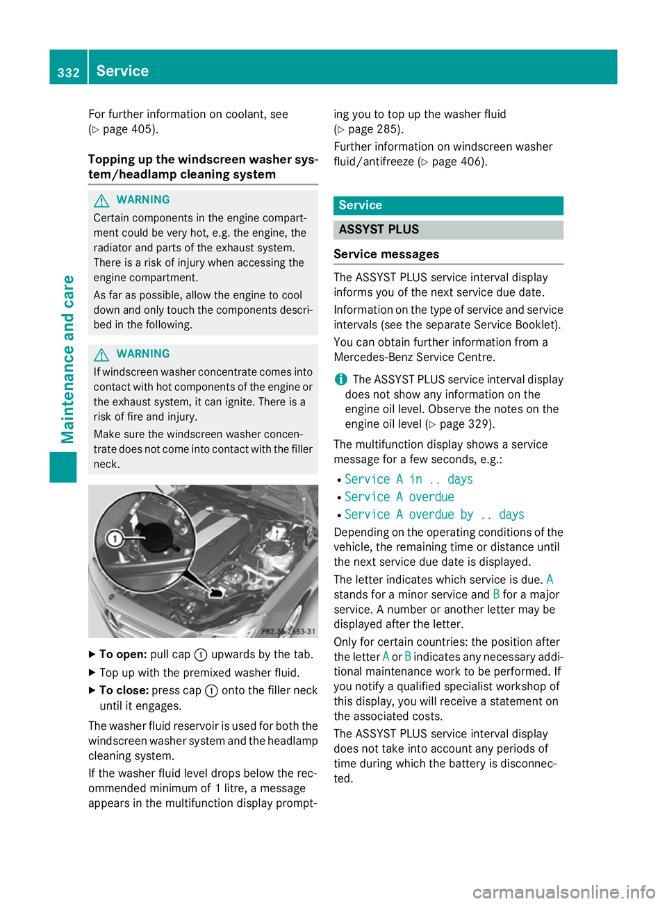
To open: pull cap:upwards by the tab.
X Top up with the premixed washer fluid.
X To close: press cap :onto the filler neck
until it engages.
The washer fluid reservoir is used for both the
windscreen washer system and the headlamp cleaning system.
If the washer fluid level drops below the rec-
ommended minimum of 1 litre, a message
appears in the multifunction display prompt- ing you to top up the washer fluid
(Y
page 285).
Further information on windscreen washer
fluid/antifreeze (Y page 406). Service
ASSYST PLUS
Service messages The ASSYST PLUS service interval display
informs you of the next service due date.
Information on the type of service and service
intervals (see the separate Service Booklet).
You can obtain further information from a
Mercedes-Benz Service Centre.
i The ASSYST PLUS service interval display
does not show any information on the
engine oil level. Observe the notes on the
engine oil level (Y page 329).
The multifunction display shows a service
message for a few seconds, e.g.:
R Service A in .. days
Service A in .. days
R Service A overdue Service A overdue
R Service A overdue by .. days
Service A overdue by .. days
Depending on the operating conditions of the
vehicle, the remaining time or distance until
the next service due date is displayed.
The letter indicates which service is due. A
A
stands for a minor service and B Bfor a major
service. A number or another letter may be
displayed after the letter.
Only for certain countries: the position after
the letter A Aor B
Bindicates any necessary addi-
tional maintenance work to be performed. If
you notify a qualified specialist workshop of
this display, you will receive a statement on
the associated costs.
The ASSYST PLUS service interval display
does not take into account any periods of
time during which the battery is disconnec-
ted. 332
ServiceMaintenance and care