2014 MERCEDES-BENZ CLS COUPE height
[x] Cancel search: heightPage 111 of 417
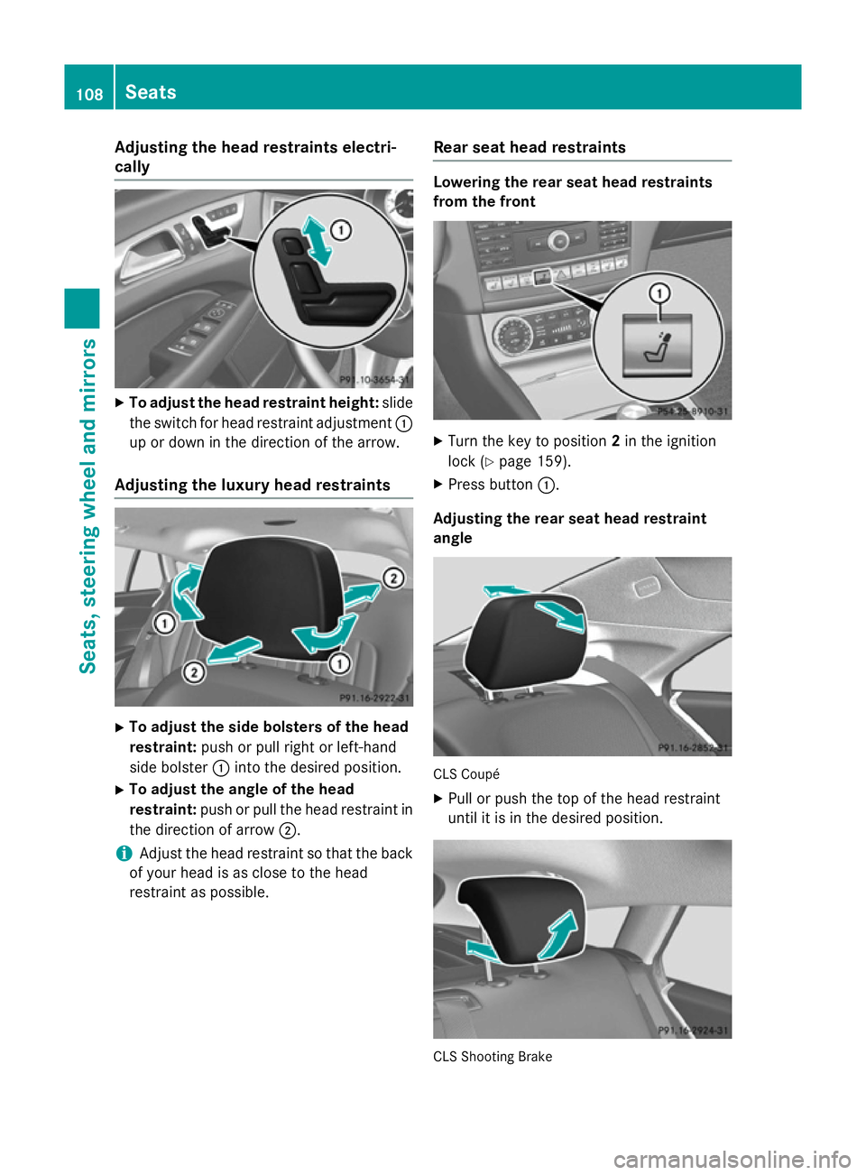
Adjusting the head restraints electri-
cally X
To adjust the head restraint height: slide
the switch for head restraint adjustment :
up or down in the direction of the arrow.
Adjusting the luxury head restraints X
To adjust the side bolsters of the head
restraint: push or pull right or left-hand
side bolster :into the desired position.
X To adjust the angle of the head
restraint: push or pull the head restraint in
the direction of arrow ;.
i Adjust the head restraint so that the back
of your head is as close to the head
restraint as possible. Rear seat head restraints Lowering the rear seat head restraints
from the front
X
Turn the key to position 2in the ignition
lock (Y page 159).
X Press button :.
Adjusting the rear seat head restraint
angle CLS Coupé
X Pull or push the top of the head restraint
until it is in the desired position. CLS Shooting Brake108
SeatsSeats
, steering wheel and mirrors
Page 112 of 417
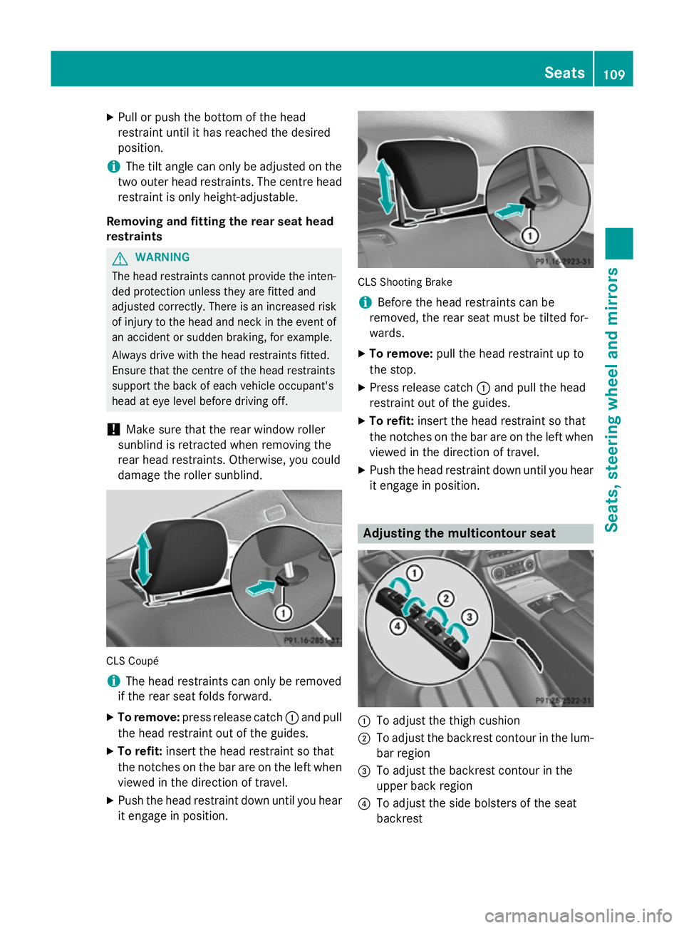
X
Pull or push the bottom of the head
restraint until it has reached the desired
position.
i The tilt angle can only be adjusted on the
two outer head restraints. The centre head restraint is only height-adjustable.
Removing and fitting the rear seat head
restraints G
WARNING
The head restraints cannot provide the inten-
ded protection unless they are fitted and
adjusted correctly. There is an increased risk of injury to the head and neck in the event of
an accident or sudden braking, for example.
Always drive with the head restraints fitted.
Ensure that the centre of the head restraints
support the back of each vehicle occupant's
head at eye level before driving off.
! Make sure that the rear window roller
sunblind is retracted when removing the
rear head restraints. Otherwise, you could
damage the roller sunblind. CLS Coupé
i
The head restraints can only be removed
if the rear seat folds forward.
X To remove: press release catch :and pull
the head restraint out of the guides.
X To refit: insert the head restraint so that
the notches on the bar are on the left when
viewed in the direction of travel.
X Push the head restraint down until you hear
it engage in position. CLS Shooting Brake
i
Before the head restraints can be
removed, the rear seat must be tilted for-
wards.
X To remove: pull the head restraint up to
the stop.
X Press release catch :and pull the head
restraint out of the guides.
X To refit: insert the head restraint so that
the notches on the bar are on the left when viewed in the direction of travel.
X Push the head restraint down until you hear
it engage in position. Adjusting the multicontour seat
:
To adjust the thigh cushion
; To adjust the backrest contour in the lum-
bar region
= To adjust the backrest contour in the
upper back region
? To adjust the side bolsters of the seat
backrest Seats
109Seats, steering wheel and mirrors Z
Page 113 of 417
You can adjust the contour of the front seats
individually so as to provide optimum support
for your back and sides.
X Turn the key to position 2in the ignition
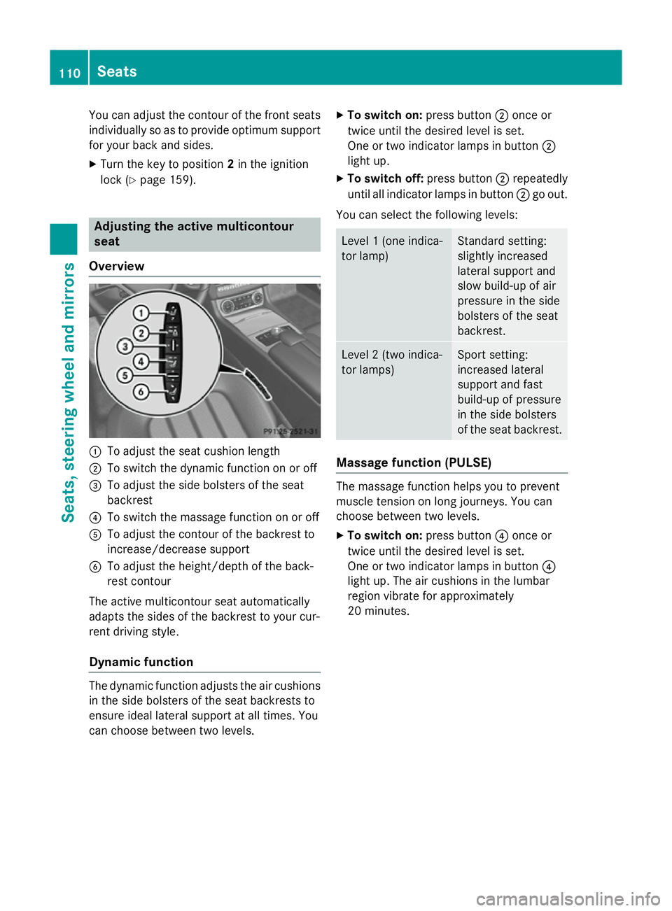
lock (Y page 159). Adjusting the active multicontour
seat
Overview :
To adjust the seat cushion length
; To switch the dynamic function on or off
= To adjust the side bolsters of the seat
backrest
? To switch the massage function on or off
A To adjust the contour of the backrest to
increase/decrease support
B To adjust the height/depth of the back-
rest contour
The active multicontour seat automatically
adapts the sides of the backrest to your cur-
rent driving style.
Dynamic function The dynamic function adjusts the air cushions
in the side bolsters of the seat backrests to
ensure ideal lateral support at all times. You
can choose between two levels. X
To switch on: press button;once or
twice until the desired level is set.
One or two indicator lamps in button ;
light up.
X To switch off: press button;repeatedly
until all indicator lamps in button ;go out.
You can select the following levels: Level 1 (one indica-
tor lamp) Standard setting:
slightly increased
lateral support and
slow build-up of air
pressure in the side
bolsters of the seat
backrest.
Level 2 (two indica-
tor lamps) Sport setting:
increased lateral
support and fast
build-up of pressure
in the side bolsters
of the seat backrest.
Massage function (PULSE)
The massage function helps you to prevent
muscle tension on long journeys. You can
choose between two levels.
X To switch on: press button?once or
twice until the desired level is set.
One or two indicator lamps in button ?
light up. The air cushions in the lumbar
region vibrate for approximately
20 minutes. 110
SeatsSeats, steering wheel and mirrors
Page 116 of 417
Problems with the seat ventilation
Problem
Possible causes/consequences and
M
MSolutions The seat ventilation has
switched off prema-
turely or cannot be
switched on. The on-board voltage is too low because too many electrical con-
sumers are switched on.
X Switch off electrical consumers that you do not need, such as
the rear window heating or interior lighting.
Once the battery is sufficiently charged, the seat ventilation will
switch back on automatically. Steering wheel
Important safety notes
G
WARNING
You could lose control of the vehicle while
driving if you:
R adjust the driver's seat, steering wheel or
mirrors
R fasten the seat belt
There is a risk of an accident.
Adjust the driver's seat, head restraint, steer-
ing wheel and mirrors and fasten your seat
belt before starting the engine. G
WARNING
Children could become trapped by the steer-
ing wheel if they adjust it. There is a risk of
injury.
When leaving the vehicle, always take the key with you and lock the vehicle. Never leave
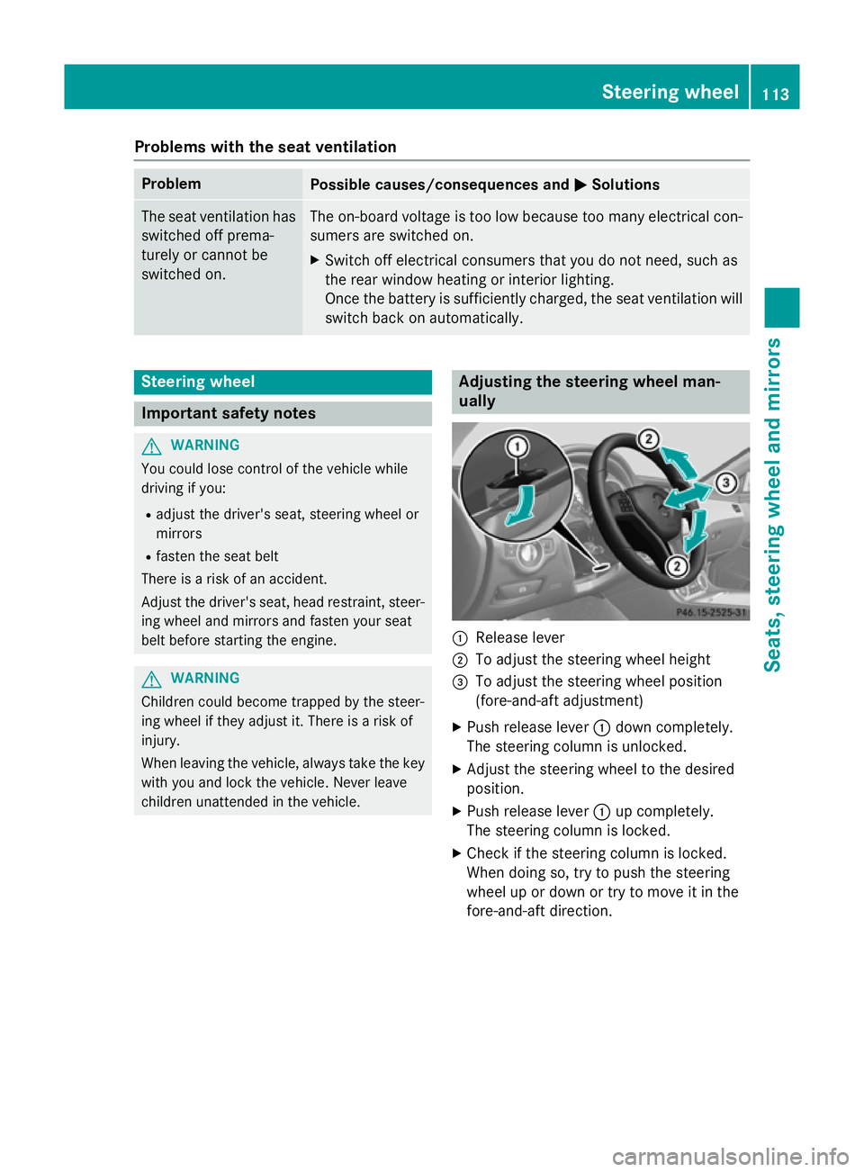
children unattended in the vehicle. Adjusting the steering wheel man-
ually
:
Release lever
; To adjust the steering wheel height
= To adjust the steering wheel position
(fore-and-aft adjustment)
X Push release lever :down completely.
The steering column is unlocked.
X Adjust the steering wheel to the desired
position.
X Push release lever :up completely.
The steering column is locked.
X Check if the steering column is locked.
When doing so, try to push the steering
wheel up or down or try to move it in the
fore-and-aft direction. Steering wheel
113Seats, steering wheel and mirrors Z
Page 117 of 417
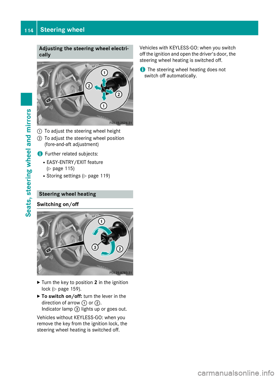
Adjusting the steering wheel electri-
cally :
To adjust the steering wheel height
; To adjust the steering wheel position
(fore-and-aft adjustment)
i Further related subjects:
R EASY-ENTRY/EXIT feature
(Y page 115)
R Storing settings (Y page 119)Steering wheel heating
Switching on/off X
Turn the key to position 2in the ignition
lock (Y page 159).
X To switch on/off: turn the lever in the
direction of arrow :or;.
Indicator lamp =lights up or goes out.
Vehicles without KEYLESS-GO: when you
remove the key from the ignition lock, the
steering wheel heating is switched off. Vehicles with KEYLESS-GO: when you switch
off the ignition and open the driver's door, the steering wheel heating is switched off.
i The steering wheel heating does not
switch off automatically. 114
Steering wheelSeats
, steering wheel and mirrors
Page 206 of 417
!
The vehicle is lowered by about 15 mm if:
R you have selected "Comfort tuning"
R you switch off the engine and
R you lock the vehicle within approximately
60 seconds
When parking, position your vehicle so that it does not make contact with the kerb as
the vehicle is lowered. Your vehicle could
otherwise be damaged.
If you unlock the vehicle within 60 seconds of
having switched the engine off, the vehicle is
lowered slightly when Comfort suspension
mode is selected.
Observe the notes on driving with a trailer
(Y page 233).
Your vehicle regulates its height automati-
cally. All-round level control ensures the best
possible suspension and constant ground
clearance, even with a laden vehicle. When
you drive fast, the vehicle is lowered auto-
matically to improve driving safety and to
reduce fuel consumption.
The following vehicle levels are possible:
R Normal
R Raised: the vehicle is raised by approx-
imately 25 mm when compared with the
normal level
R Lowered: the vehicle is lowered by approx-
imately 10 mm when compared with the
normal level
The "Normal" and "Raised" vehicle levels can be set manually.
The "Lowered" vehicle level is set automati-
cally:
R at speeds above 140 km/h
R if you have selected "Comfort mode"
(Y page 204) and then lock the vehicle
within 60 seconds of the engine being
switched off
R if you have selected "Sport mode"
(Y page 204) Setting the vehicle level
Select the "Normal" setting for normal road
surfaces and "Raised" for driving with snow
chains or on particularly poor road surfaces.
Your selection remains stored even if you
remove the key from the ignition lock.
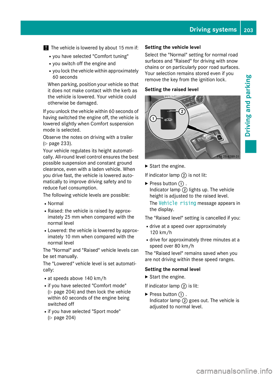
Setting the raised level X
Start the engine.
If indicator lamp ;is not lit:
X Press button :.
Indicator lamp ;lights up. The vehicle
height is adjusted to the raised level.
The Vehicle rising Vehicle rising message appears in
the display.
The "Raised level" setting is cancelled if you:
R drive at a speed over approximately
120 km/h
R drive for approximately three minutes at a
speed over 80 km/h
The "Raised level" remains saved when you
are not driving within these speed ranges.
Setting the normal level
X Start the engine.
If indicator lamp ;is lit:
X Press button :.
Indicator lamp ;goes out. The vehicle is
adjusted to normal level. Driving systems
203Driving and parking Z
Page 214 of 417
Parking tips:
R on narrow roads, drive as closely as possi-
ble past the parking space.
R parking spaces that are littered or over-
grown might be identified or measured
incorrectly.
R parking spaces that are partially occupied
by trailer drawbars might not be identified
as such or be measured incorrectly.
R snowfall or heavy rain may lead to a parking
space being measured inaccurately.
R pay attention to the PARKTRONIC
(Y page 208) warning messages during the
parking procedure.
R at any time, you can intervene in the steer-
ing procedure to correct it. Active Parking
Assist will then be cancelled.
R when transporting a load which protrudes
from your vehicle, you should not use
Active Parking Assist.
R never use Active Parking Assist when snow
chains are fitted.
R make sure that the tyre pressures are
always correct. This has a direct influence
on the parking characteristics of the vehi-
cle.
Use Active Parking Assist for parking spaces:
R that are parallel to the direction of travel
R that are on straight roads, not bends
R that are on the same level as the road, e.g.
not on the pavement
Detecting parking spaces Objects located above the height range of
Active Parking Assist will not be detected
when the parking space is measured. These
are not taken into account when the parking
procedure is calculated, e.g. overhanging
loads, tail sections or loading ramps of goods
vehicles. G
WARNING
If objects are located above the detection
range, Active Parking Assist may start to steer into the parking space too soon. As a result,
you could cause a collision. There is a risk of
an accident.
If objects are located above the detection
range, stop the vehicle and switch Active
Parking Assist off.
For further information on the detection
range (Y page 207).
Active Parking Assist does not support you
parking in spaces that are parallel to the
direction of travel if:
R the parking space is on a kerb stone
R the system reads the parking space as
being blocked, for example by foliage or
grass paving blocks
R the area is too small for the vehicle to
manoeuvre into
R the parking space is bordered by an obsta-
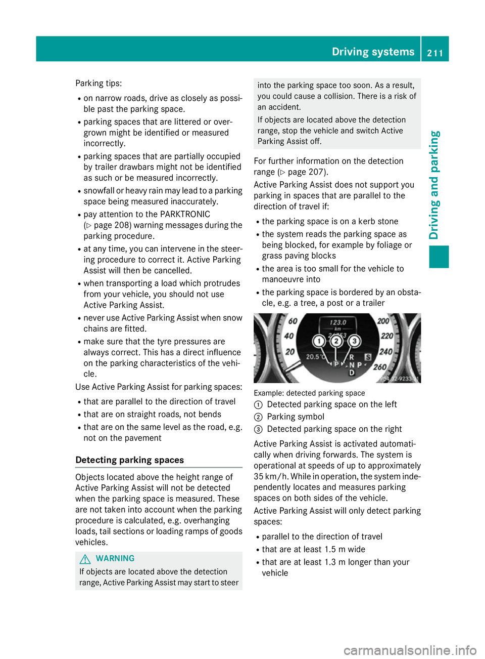
cle, e.g. a tree, a post or a trailer Example: detected parking space
:
Detected parking space on the left
; Parking symbol
= Detected parking space on the right
Active Parking Assist is activated automati-
cally when driving forwards. The system is
operational at speeds of up to approximately
35 km/h. While in operation, the system inde-
pendently locates and measures parking
spaces on both sides of the vehicle.
Active Parking Assist will only detect parking spaces:
R parallel to the direction of travel
R that are at least 1.5 m wide
R that are at least 1.3 m longer than your
vehicle Driving systems
211Driving and parking Z
Page 221 of 417
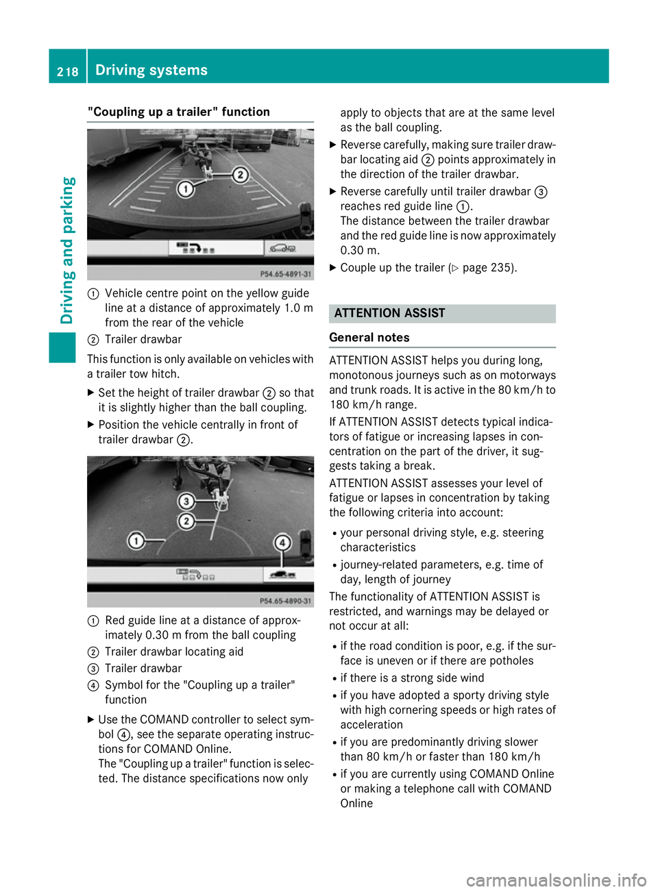
"Coupling up a trailer" function
:
Vehicle centre point on the yellow guide
line at a distance of approximately 1.0 m
from the rear of the vehicle
; Trailer drawbar
This function is only available on vehicles with
a trailer tow hitch.
X Set the height of trailer drawbar ;so that
it is slightly higher than the ball coupling.
X Position the vehicle centrally in front of
trailer drawbar ;. :
Red guide line at a distance of approx-
imately 0.30 m from the ball coupling
; Trailer drawbar locating aid
= Trailer drawbar
? Symbol for the "Coupling up a trailer"
function
X Use the COMAND controller to select sym-
bol ?, see the separate operating instruc-
tions for COMAND Online.
The "Coupling up a trailer" function is selec- ted. The distance specifications now only apply to objects that are at the same level
as the ball coupling.
X Reverse carefully, making sure trailer draw-
bar locating aid ;points approximately in
the direction of the trailer drawbar.
X Reverse carefully until trailer drawbar =
reaches red guide line :.
The distance between the trailer drawbar
and the red guide line is now approximately
0.30 m.
X Couple up the trailer (Y page 235). ATTENTION ASSIST
General notes ATTENTION ASSIST helps you during long,
monotonous journeys such as on motorways and trunk roads. It is active in the 80 km/h to
180 km/h range.
If ATTENTION ASSIST detects typical indica-
tors of fatigue or increasing lapses in con-
centration on the part of the driver, it sug-
gests taking a break.
ATTENTION ASSIST assesses your level of
fatigue or lapses in concentration by taking
the following criteria into account:
R your personal driving style, e.g. steering
characteristics
R journey-related parameters, e.g. time of
day, length of journey
The functionality of ATTENTION ASSIST is
restricted, and warnings may be delayed or
not occur at all:
R if the road condition is poor, e.g. if the sur-
face is uneven or if there are potholes
R if there is a strong side wind
R if you have adopted a sporty driving style
with high cornering speeds or high rates of
acceleration
R if you are predominantly driving slower
than 80 km/h or faster than 180 km/h
R if you are currently using COMAND Online
or making a telephone call with COMAND
Online 218
Driving systemsDriving and pa
rking