2014 MERCEDES-BENZ CLS COUPE battery location
[x] Cancel search: battery locationPage 16 of 417

Insect protection on the radiator
.... 329
Instrument cluster
Overview .......................................... 32
Settings ........................................ .252
Warning and indicator lamps ........... 34
Instrument cluster lighting .............. 252
Intelligent Light System
Activating/deactivating ................. 253
Display message ............................ 269
Overview ........................................ 127
Setting the dipped-beam head-
lamps for driving on the right/left .. 253
Interior lighting
Automatic control system .............. 130
Delayed switch-off (on-board
computer) ...................................... 254
Emergency lighting ........................ 131
Manual control ............................... 131
Overview ........................................ 130
Reading lamp ................................. 130
Setting brightness for display/
switches (on-board computer) ....... 252
Setting the ambient lighting
brightness (on-board computer) .... 253
Setting the ambient lighting col-
our (on-board computer) ................ 254
Interior motion sensor
Deactivating ..................................... 80
Function .......................................... .79
Priming ............................................ 79
Switching off .................................... 80
ISOFIX child seat securing system ....57J
Jack Storage location ............................3 45
Using ............................................. 375
Jump starting (engine) ......................355 K
Key Changing the battery ....................... 86
Checking the battery ....................... 85
Convenience closing feature ............ 98
Convenience opening feature .......... 97
Display message ............................ 285 Door central locking/unlocking ....... 83
Emergency key element ................... 84
Important safety notes .................... 82
Loss ................................................. 87
Modifying the programming ............. 84
Overview .......................................... 82
Positions (ignition lock) ................. 159
Problem (malfunction) ..................... 87
Starting the engine ........................ 161
Key positions
Key ................................................ 159
KEYLESS GO .................................. 159
KEYLESS-GO
Convenience closing ........................ 98
Display message ............................ 285
Locking ............................................ 83
Removing the Start/Stop button ... 160
Start/Stop button .......................... 159
Starting the engine ........................ 162
Unlocking ......................................... 83
Kickdown
Driving tips ................................... .171
Manual drive program .................... 176
Kneebag ............................................... 49 L
Lamps see Warning and indicator lamps
Lane Keeping Assist
Activating/deactivating ................. 251
Display message ............................ 275
Function/informatio n.................... 225
Lane package ..................................... 223
Lap time (RACETIMER) ...................... 259
Lashing eyelets ................................. 306
Licence plate lamp (display mes-
sage) ................................................... 268
Light sensor (display message) ....... 269
Lighting
see Lights
Lights
Activating/deactivating the Intel-
ligent Light System ........................ 253
Activating/deactivating the inte-
rior lighting delayed switch-off ....... 254
Active light function ....................... 127
Adaptive Highbeam Assist ............. 128 Index
13
Page 153 of 417

Auxiliary heating
Important safety notes G
DANGER
If the exhaust pipe is blocked or sufficient
ventilation is not possible, toxic exhaust
fumes can enter the vehicle, especially car-
bon monoxide. This is the case, e.g. in
enclosed spaces, or if the vehicle is stuck in
snow. There is a risk of fatal injuries.
You should switch off the auxiliary heating in
enclosed spaces which do not have an extrac- tion system, e.g. a garage. If the vehicle is
stuck in snow and you must leave the auxiliary
heating running, keep the exhaust pipe and
the area around the vehicle clear of snow. To guarantee a sufficient supply of fresh air, open
a window on the side of the vehicle away from the wind. G
WARNING
When the auxiliary heating is switched on,
parts of the vehicle can become very hot.
Flammable materials such as leaves, grass or twigs may ignite if they come into contact
with:
R hot parts of the exhaust system
R the exhaust gas itself
There is a risk of fire.
When the auxiliary heating is switched on,
make sure that:
R no flammable materials come into contact
with hot vehicle components
R the exhaust gas can escape from the
exhaust pipe unhindered
R the exhaust gas does not come into contact
with flammable materials.
The auxiliary heating and the exhaust gas dis- charge location can be found in front of the
right-hand front wheel.
! Operating the auxiliary heating/ventila-
tion draws on the vehicle battery. After you
have heated or ventilated the vehicle a maximum of two times, drive for a longer
distance.
i Switch the auxiliary heating on regularly
once a month for about ten minutes.
The auxiliary heating heats the air in the vehi- cle interior to the set temperature. This
occurs without using the heat of the running
engine. The auxiliary heating is operated
directly using the vehicle's fuel. For this rea-
son, the tank content must be at least at
reserve fuel level to ensure that the auxiliary
heating functions.
The auxiliary heating/ventilation automati-
cally adjusts to changes in temperature and
weather conditions. For this reason, the aux- iliary heating could switch from ventilation
mode to heating mode or from heating mode
to ventilation mode.
The auxiliary heating switches off automati-
cally after 50 minutes. This time limit can be
altered. To do this, visit a qualified specialist
workshop.
You cannot use the auxiliary ventilation to
cool the vehicle interior to a temperature
lower than the outside temperature.
Before switching on X
Turn the key to position 2in the ignition
lock (Y page 159).
X Set the desired temperature.
Auxiliary heating or ventilation can also be
switched on if the manually set climate con-
trol is activated. Optimum comfort can be
attained when the system is set to automatic
mode. Set the temperature to 22 †.
The auxiliary heating/ventilation can be acti-
vated or deactivated using the remote control or the button on the centre console.
The on-board computer can be used to spec-ify up to three departure times, one of which
may be preselected (Y page 256).150
Operating the climate control systemClimate cont
rol
Page 155 of 417

Checking the status of the auxiliary heat-
ing/ventilation
X Press the ,or. button.
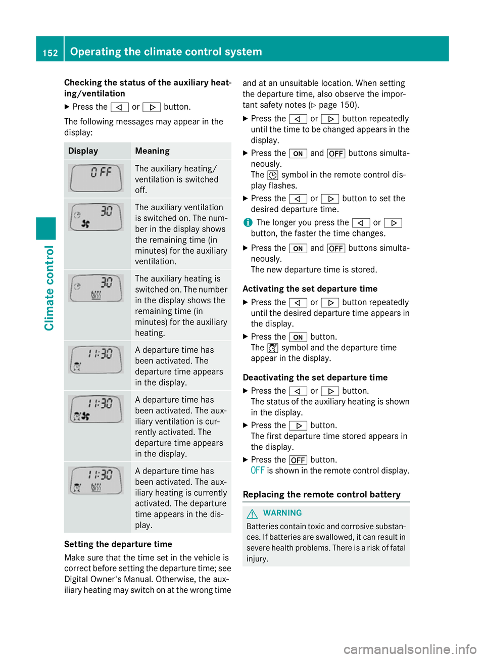
The following messages may appear in the
display: Display Meaning
The auxiliary heating/
ventilation is switched
off.
The auxiliary ventilation
is switched on. The num-
ber in the display shows
the remaining time (in
minutes) for the auxiliary
ventilation. The auxiliary heating is
switched on. The number
in the display shows the
remaining time (in
minutes) for the auxiliary heating. A departure time has
been activated. The
departure time appears
in the display.
A departure time has
been activated. The aux-
iliary ventilation is cur-
rently activated. The
departure time appears
in the display.
A departure time has
been activated. The aux-
iliary heating is currently
activated. The departure
time appears in the dis-
play.
Setting the departure time
Make sure that the time set in the vehicle is
correct before setting the departure time; see Digital Owner's Manual. Otherwise, the aux-
iliary heating may switch on at the wrong time and at an unsuitable location. When setting
the departure time, also observe the impor-
tant safety notes (Y
page 150).
X Press the ,or. button repeatedly
until the time to be changed appears in the display.
X Press the uand^ buttons simulta-
neously.
The Îsymbol in the remote control dis-
play flashes.
X Press the ,or. button to set the
desired departure time.
i The longer you press the
,or.
button, the faster the time changes.
X Press the uand^ buttons simulta-
neously.
The new departure time is stored.
Activating the set departure time X Press the ,or. button repeatedly
until the desired departure time appears in
the display.
X Press the ubutton.
The Ísymbol and the departure time
appear in the display.
Deactivating the set departure time
X Press the ,or. button.
The status of the auxiliary heating is shown in the display.
X Press the .button.
The first departure time stored appears in
the display.
X Press the ^button.
OFF
OFF is shown in the remote control display.
Replacing the remote control battery G
WARNING
Batteries contain toxic and corrosive substan- ces. If batteries are swallowed, it can result in
severe health problems. There is a risk of fatal injury. 152
Operating the climate control systemClimate control
Page 363 of 417

The towing eye can be used to pull the vehicle
onto a trailer or transporter for transporta-
tion.
The towing eyes or trailer tow hitch can be
used to pull the vehicle onto a trailer or trans-
porter if you wish to transport it.
X Turn the key to position 2in the ignition
lock.
X Shift the automatic transmission to posi-
tion N.
As soon as the vehicle is loaded:
X Prevent the vehicle from rolling away by
applying the parking brake.
X Shift the automatic transmission to posi-
tion P.
X Turn the key in the ignition lock to position
0 and remove the key from the ignition
lock.
X Secure the vehicle. Notes for 4MATIC vehicles
! Vehicles with 4MATIC must not be towed
with the front or rear axle raised; otherwise,
the transmission may be damaged.
If the vehicle has transmission damage or
damage to the front or rear axle, have it trans- ported on a transporter or trailer.
In the event of damage to the electrical
system
If the battery is defective, the automatic
transmission will be locked in position P. To
shift the automatic transmission to position
N, you must provide power to the vehicle's
electrical system in the same way as when
jump-starting (Y page 355).
Have the vehicle transported on a transporter
or trailer. Tow-starting (emergency engine
starting)
! Vehicles with automatic transmission
must not be tow-started. The transmission
may otherwise be damaged.
i You can find information on "Jump-start-
ing" under (Y page 355). Electrical fuses
Important safety notes
G
WARNING
If you manipulate, bridge or replace a faulty
fuse with a fuse of a higher amperage, the
electric cables could be overloaded. This may result in a fire. There is a risk of an accident
and injury.
Always replace faulty fuses with specified new fuses of the correct amperage.
! Only use fuses that have been approved
for Mercedes-Benz vehicles and which
have the correct fuse rating for the system concerned. Otherwise, components or sys-
tems could be damaged.
The fuses in your vehicle serve to disconnect
faulty circuits. If a fuse blows, all the compo- nents on the circuit and their functions will
fail.
Blown fuses must be replaced with fuses of
the same rating, which you can recognise by
the colour and fuse rating. The fuse ratings
are listed in the fuse allocation chart.
If the newly inserted fuse also blows, have the
cause traced and rectified at a qualified spe-
cialist workshop, e.g. a Mercedes-Benz Ser-
vice Centre. Before replacing a fuse
Observe the important safety notes
(Y page 360) 360
Electrical fusesBreakdown assistance