2014 MERCEDES-BENZ CLS COUPE tow
[x] Cancel search: towPage 394 of 417
R
Do not switch off ESP ®
.
R Have the spare wheel/emergency spare
wheel in question replaced at the nearest
qualified specialist workshop. Make sure
that the wheel/tyre dimensions and tyre
type are correct.
When using an emergency spare wheel or
spare wheel of a different size, you must not
exceed the maximum speed of 80 km/h.
Snow chains must not be fitted to emergency spare wheels. General notes
You should regularly check the pressure of all your tyres, including the emergency spare
wheel, particularly prior to long trips, and cor-
rect the pressure as necessary (Y page 367).
The value on the wheel is valid. In addition, the
emergency spare wheel tyre pressure can be found under "Technical data" (Y page 394).
An emergency spare wheel may also be fitted against the direction of rotation. Observe the
time restriction on use as well as the speed
limitation specified on the emergency spare
wheel.
Replace the tyres after six years at the latest,
regardless of wear. This also applies to the
emergency spare wheel.
i If you are driving with the collapsible
emergency spare wheel fitted, the tyre
pressure loss warning system or the tyre
pressure monitor cannot function reliably.
Only restart the tyre pressure loss warning
system/tyre pressure monitor when the
defective wheel has been replaced with a
new wheel.
Vehicles with tyre pressure monitor: after
mounting an emergency spare wheel, the
system may still display the tyre pressure of the removed wheel for a few minutes. The
value displayed for the mounted emer-
gency spare wheel is not the same as the
current tyre pressure of the emergency
spare wheel. Removing the "Minispare" emer-
gency spare wheel/collapsible emer-
gency spare wheel
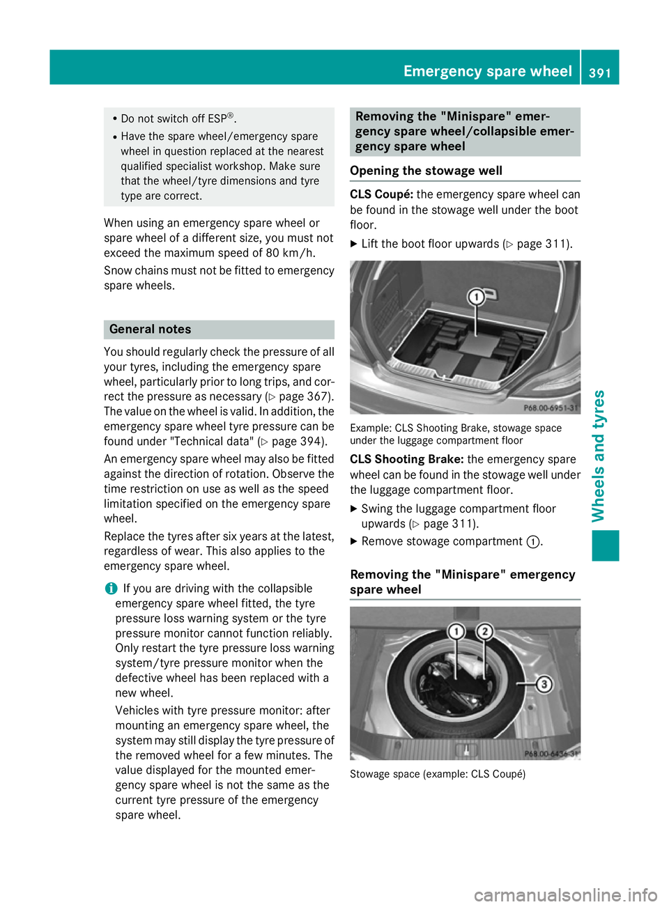
Opening the stowage well CLS Coupé:
the emergency spare wheel can
be found in the stowage well under the boot
floor.
X Lift the boot floor upwards (Y page 311). Example: CLS Shooting Brake, stowage space
under the luggage compartment floor
CLS Shooting Brake: the emergency spare
wheel can be found in the stowage well under
the luggage compartment floor.
X Swing the luggage compartment floor
upwards (Y page 311).
X Remove stowage compartment :.
Removing the "Minispare" emergency
spare wheel Stowage space (example: CLS Coupé) Emergency spare
wheel
391Wheels an d tyres Z
Page 395 of 417
X
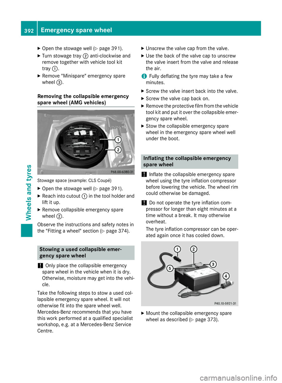
Open the stowage well (Y page 391).
X Turn stowage tray ;anti-clockwise and
remove together with vehicle tool kit
tray :.
X Remove "Minispare" emergency spare
wheel =.
Removing the collapsible emergency
spare wheel (AMG vehicles) Stowage space (example: CLS Coupé)
X Open the stowage well (Y page 391).
X Reach into cutout :in the tool holder and
lift it up.
X Remove collapsible emergency spare
wheel ;.
Observe the instructions and safety notes in
the "Fitting a wheel" section (Y page 374).Stowing a used collapsible emer-
gency spare wheel
! Only place the collapsible emergency
spare wheel in the vehicle when it is dry.
Otherwise, moisture may get into the vehi-
cle.
Take the following steps to stow a used col-
lapsible emergency spare wheel. It will not
otherwise fit into the spare wheel well.
Mercedes-Benz recommends that you have
this work performed at a qualified specialist
workshop, e.g. at a Mercedes-Benz Service
Centre. X
Unscrew the valve cap from the valve.
X Use the back of the valve cap to unscrew
the valve insert from the valve and release
the air.
i Fully deflating the tyre may take a few
minutes.
X Screw the valve insert back into the valve.
X Screw the valve cap back on.
X Remove the protective film from the vehicle
tool kit and put it over the collapsible emer-
gency spare wheel.
X Stow the collapsible emergency spare
wheel in the emergency spare wheel well
under the boot. Inflating the collapsible emergency
spare wheel
! Inflate the collapsible emergency spare
wheel using the tyre inflation compressor
before lowering the vehicle. The wheel rim
could otherwise be damaged.
! Do not operate the tyre inflation com-
pressor for longer than eight minutes at a
time without a break. It may otherwise
overheat.
The tyre inflation compressor can be oper-
ated again once it has cooled down. X
Mount the collapsible emergency spare
wheel as described (Y page 373).392
Emergency spare wheelWheels and tyres
Page 396 of 417
The collapsible emergency spare wheel
must be mounted before it is inflated.
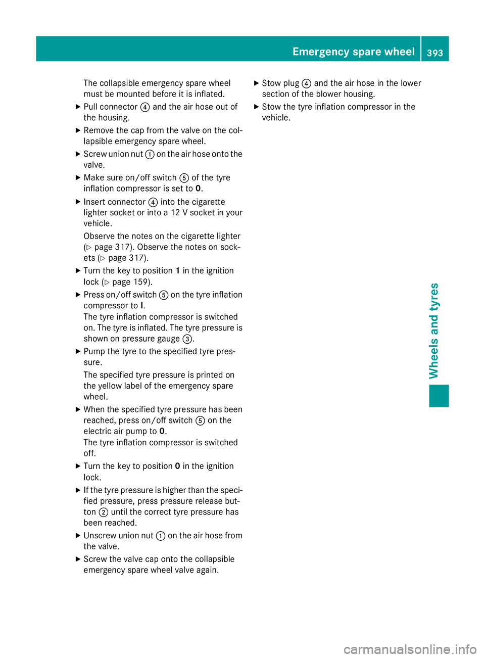
X Pull connector ?and the air hose out of
the housing.
X Remove the cap from the valve on the col-
lapsible emergency spare wheel.
X Screw union nut :on the air hose onto the
valve.
X Make sure on/off switch Aof the tyre
inflation compressor is set to 0.
X Insert connector ?into the cigarette
lighter socket or into a 12 V socket in your vehicle.
Observe the notes on the cigarette lighter
(Y page 317). Observe the notes on sock-
ets (Y page 317).
X Turn the key to position 1in the ignition
lock (Y page 159).
X Press on/off switch Aon the tyre inflation
compressor to I.
The tyre inflation compressor is switched
on. The tyre is inflated. The tyre pressure is shown on pressure gauge =.
X Pump the tyre to the specified tyre pres-
sure.
The specified tyre pressure is printed on
the yellow label of the emergency spare
wheel.
X When the specified tyre pressure has been
reached, press on/off switch Aon the
electric air pump to 0.
The tyre inflation compressor is switched
off.
X Turn the key to position 0in the ignition
lock.
X If the tyre pressure is higher than the speci-
fied pressure, press pressure release but-
ton ;until the correct tyre pressure has
been reached.
X Unscrew union nut :on the air hose from
the valve.
X Screw the valve cap onto the collapsible
emergency spare wheel valve again. X
Stow plug ?and the air hose in the lower
section of the blower housing.
X Stow the tyre inflation compressor in the
vehicle. Emergency spare wheel
393Wheels and tyres Z
Page 398 of 417
Useful information
............................396
Information on technical data .........396
Vehicle electronics ...........................396
Identification plates .........................398
Service products and capacities .....399
Vehicle data ...................................... 407
Trailer tow hitch ................................ 409 395Technical data
Page 406 of 417
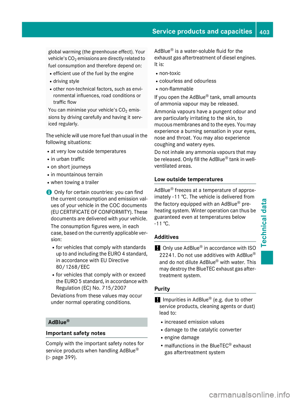
global warming (the greenhouse effect). Your
vehicle's CO 2emissions are directly related to
fuel consumption and therefore depend on:
R efficient use of the fuel by the engine
R driving style
R other non-technical factors, such as envi-
ronmental influences, road conditions or
traffic flow
You can minimise your vehicle's CO 2emis-
sions by driving carefully and having it serv-
iced regularly.
The vehicle will use more fuel than usual in the following situations:
R at very low outside temperatures
R in urban traffic
R on short journeys
R in mountainous terrain
R when towing a trailer
i Only for certain countries: you can find
the current consumption and emission val-
ues of your vehicle in the COC documents
(EU CERTIFICATE OF CONFORMITY). These documents are delivered with your vehicle.
The consumption figures were, in each
case, based on the currently applicable ver-sion:
R for vehicles that comply with standards
up to and including the EURO 4 standard,
in accordance with EU Directive
80/1268/EEC
R for vehicles that comply with or exceed
the EURO 5 standard, in accordance with
Regulation (EC) No. 715/2007
Deviations from these values may occur
under normal operating conditions. AdBlue
®
Important safety notes Comply with the important safety notes for
service products when handling AdBlue
®
(Y page 399). AdBlue
®
is a water-soluble fluid for the
exhaust gas aftertreatment of diesel engines. It is:
R non-toxic
R colourless and odourless
R non-flammable
If you open the AdBlue ®
tank, small amounts
of ammonia vapour may be released.
Ammonia vapours have a pungent odour and
are particularly irritating to the skin, to
mucous membranes and to the eyes. You may experience a burning sensation in your eyes,
nose and throat. You may also experience
coughing and watery eyes.
Do not inhale any ammonia vapours that may
be released. Only fill the AdBlue ®
tank in well-
ventilated areas.
Low outside temperatures AdBlue
®
freezes at a temperature of approx-
imately -11 †. The vehicle is delivered from
the factory equipped with an AdBlue ®
pre-
heating system. Winter operation can thus be guaranteed even at temperatures below
-11 †.
Additives !
Only use AdBlue ®
in accordance with ISO
22241. Do not use additives with AdBlue ®
and do not dilute AdBlue ®
with water. This
may destroy the BlueTEC exhaust gas after-
treatment system.
Purity !
Impurities in AdBlue ®
(e.g. due to other
service products, cleaning agents or dust)
lead to:
R increased emission values
R damage to the catalytic converter
R engine damage
R malfunctions in the BlueTEC ®
exhaust
gas aftertreatment system Service products and capacities
403Technical data Z
Page 412 of 417
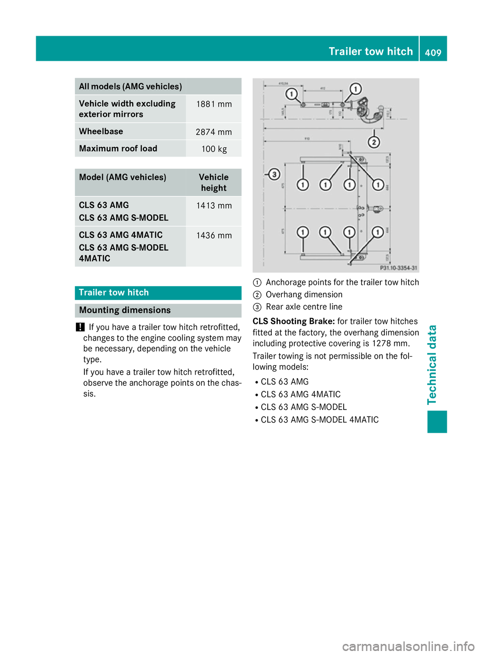
All models (AMG vehicles)
Vehicle width excluding
exterior mirrors
1881 mm
Wheelbase
2874 mm
Maximum roof load
100 kg
Model (AMG vehicles) Vehicle
height CLS 63 AMG
CLS 63 AMG S-MODEL
1413 mm
CLS 63 AMG 4MATIC
CLS 63 AMG S-MODEL
4MATIC
1436 mm
Trailer tow hitch
Mounting dimensions
! If you have a trailer tow hitch retrofitted,
changes to the engine cooling system may
be necessary, depending on the vehicle
type.
If you have a trailer tow hitch retrofitted,
observe the anchorage points on the chas- sis. :
Anchorage points for the trailer tow hitch
; Overhang dimension
= Rear axle centre line
CLS Shooting Brake: for trailer tow hitches
fitted at the factory, the overhang dimension
including protective covering is 1278 mm.
Trailer towing is not permissible on the fol-
lowing models:
R CLS 63 AMG
R CLS 63 AMG 4MATIC
R CLS 63 AMG S-MODEL
R CLS 63 AMG S-MODEL 4MATIC Trailer tow hitch
409Technical data Z
Page 413 of 417
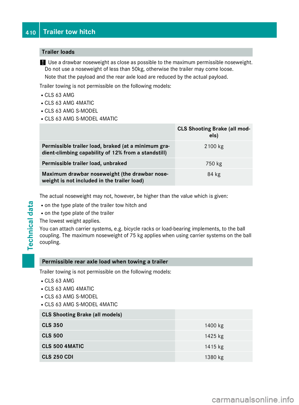
Trailer loads
! Use a drawbar noseweight as close as possible to the maximum permissible noseweight.
Do not use a noseweight of less than 50kg, otherwise the trailer may come loose.
Note that the payload and the rear axle load are reduced by the actual payload.
Trailer towing is not permissible on the following models:
R CLS 63 AMG
R CLS 63 AMG 4MATIC
R CLS 63 AMG S-MODEL
R CLS 63 AMG S-MODEL 4MATIC CLS Shooting Brake (all mod-
els) Permissible trailer load, braked (at a minimum gra-
dient-climbing capability of 12% from a standstill)
2100 kg
Permissible trailer load, unbraked
750 kg
Maximum drawbar noseweight (the drawbar nose-
weight is not included in the trailer load)
84 kg
The actual noseweight may not, however, be higher than the value which is given:
R on the type plate of the trailer tow hitch and
R on the type plate of the trailer
The lowest weight applies.
You can attach carrier systems, e.g. bicycle racks or load-bearing implements, to the ball
coupling. The maximum noseweight of 75 kg applies when using carrier systems on the ball
coupling. Permissible rear axle load when towing a trailer
Trailer towing is not permissible on the following models:
R CLS 63 AMG
R CLS 63 AMG 4MATIC
R CLS 63 AMG S-MODEL
R CLS 63 AMG S-MODEL 4MATIC CLS Shooting Brake (all models)
CLS 350
1400 kg
CLS 500
1425 kg
CLS 500 4MATIC
1415 kg
CLS 250 CDI
1380 kg410
Trailer tow hitchTechnical data
Page 414 of 417
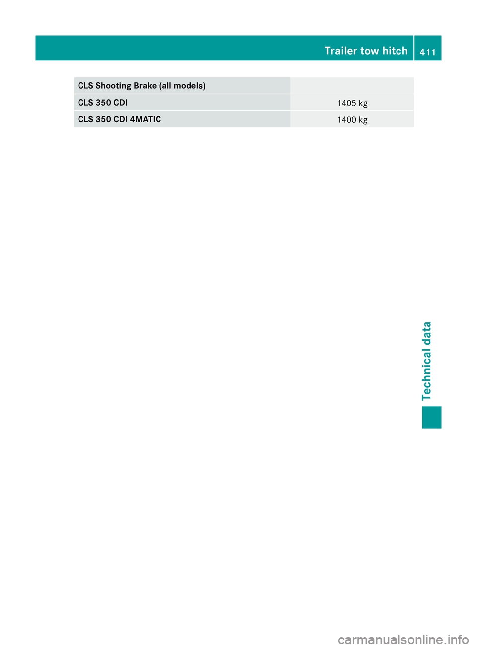
CLS Shooting Brake (all models)
CLS 350 CDI
1405 kg
CLS 350 CDI 4MATIC
1400 kgTrailer tow hitch
411Technical data Z