2014 MERCEDES-BENZ C-CLASS ESTATE ignition
[x] Cancel search: ignitionPage 245 of 489
mine which warning display is active when the
engine is running. Transmission
position Warning display
D
Front area activated
R,
Nor the vehicle
is rolling back-
wards Rear and front areas
activated P
No areas activated
One or more segments light up as the vehicle
approaches an obstacle, depending on the
vehicle's distance from the obstacle.
From the:
R sixth segment onwards, you will hear an
intermittent warning tone for approx-
imately two seconds.
R seventh segment onwards, you will hear a
warning tone for approximately two sec-
onds. This indicates that you have now
reached the minimum distance.
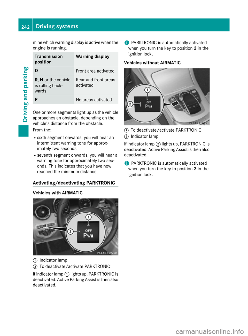
Activating/deactivating PARKTRONIC Vehicles with AIRMATIC
:
Indicator lamp
; To deactivate/activate PARKTRONIC
If indicator lamp :lights up, PARKTRONIC is
deactivated. Active Parking Assist is then also
deactivated. i
PARKTRONIC is automatically activated
when you turn the key to position 2in the
ignition lock.
Vehicles without AIRMATIC :
To deactivate/activate PARKTRONIC
; Indicator lamp
If indicator lamp ;lights up, PARKTRONIC is
deactivated. Active Parking Assist is then also
deactivated.
i PARKTRONIC is automatically activated
when you turn the key to position 2in the
ignition lock. 242
Driving systemsDriving and parking
Page 246 of 489
Problems with PARKTRONIC
Problem
Possible causes/consequences and
M
MSolutions Only the red segments
in the PARKTRONIC
warning displays are lit.
You also hear a warning
tone for approximately
two seconds.
PARKTRONIC is then
deactivated and the
indicator lamp on the
PARKTRONIC button
lights up. PARKTRONIC has malfunctioned and has been deactivated.
X If problems persist, have PARKTRONIC checked at a qualified
specialist workshop. Only the red segments
in the PARKTRONIC
warning displays are lit.
PARKTRONIC is then
deactivated. The PARKTRONIC sensors are dirty or there is interference.
X Clean the PARKTRONIC sensors (Y page 405).
X Switch the ignition back on. The problem may be caused by an external source of radio or
ultrasound waves.
X See if PARKTRONIC functions in a different location. Active Parking Assist
General notes Active Parking Assist is an electronic parking
aid with ultrasound. It measures the road on
both sides of the vehicle. A parking symbol
indicates a suitable parking space. Active
steering intervention and brake application
can assist you during parking and when exit-
ing a parking space. You may also use
PARKTRONIC (Y page 240).
Important safety notes Active Parking Assist is only an aid. It is not a
substitute for your attention to the immediate
surroundings. The responsibility for safe
manoeuvring and parking remains with you.
Make sure that no persons, animals or
objects are in the manoeuvring range.
When PARKTRONIC is switched off, Active
Parking Assist is also unavailable. For vehicles with the trailer tow hitch folded
out, the minimum length for parking spaces is
slightly longer.
If you have attached a trailer to your vehicle,
you should not use Active Parking Assist.
Once the electrical connection is established
between your vehicle and the trailer, Active
Parking Assist is no longer available.
PARKTRONIC is deactivated for the rear area. G
WARNING
While parking or pulling out of a parking
space, the vehicle swings out and can drive
onto areas of the oncoming lane. This could
cause you to collide with other road users.
There is a risk of an accident.
Pay attention to other road users. Stop the
vehicle if necessary or cancel the Active Park- ing Assist parking procedure.
! If unavoidable, you should drive over
obstacles such as kerbs slowly and not at a Driving systems
243Driving and parking Z
Page 252 of 489
R
if there is a sudden change in temperature,
e.g. when driving into a heated garage in
winter
R if the camera lens is dirty or obstructed.
Observe the notes on cleaning
(Y page 405)
R if the rear of your vehicle is damaged. In this
case, have the camera position and setting checked at a qualified specialist workshop.
The field of vision and other functions of the
reversing camera may be restricted due to
additional accessories on the rear of the vehi-
cle (e.g. licence plate holder, bicycle rack).
i The reversing camera is protected from
raindrops and dust by means of a flap.
When the reversing camera is activated,
this flap opens.
The flap closes again when:
R you have finished the manoeuvring proc-
ess
R you switch off the engine
R you open the luggage compartment
Observe the notes on cleaning
(Y page 405).
For technical reasons, the flap may remain
open briefly after the reversing camera has been deactivated.
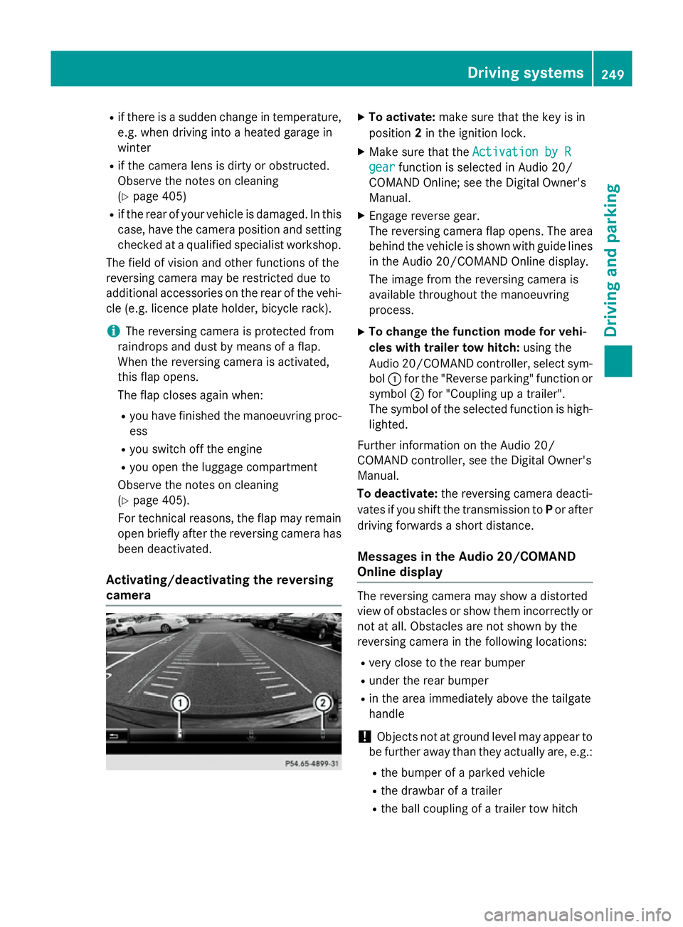
Activating/deactivating the reversing
camera X
To activate: make sure that the key is in
position 2in the ignition lock.
X Make sure that the Activation by R Activation by R
gear
gear function is selected in Audio 20/
COMAND Online; see the Digital Owner's
Manual.
X Engage reverse gear.
The reversing camera flap opens. The area
behind the vehicle is shown with guide lines
in the Audio 20/COMAND Online display.
The image from the reversing camera is
available throughout the manoeuvring
process.
X To change the function mode for vehi-
cles with trailer tow hitch: using the
Audio 20/COMAND controller, select sym-
bol :for the "Reverse parking" function or
symbol ;for "Coupling up a trailer".
The symbol of the selected function is high-
lighted.
Further information on the Audio 20/
COMAND controller, see the Digital Owner's
Manual.
To deactivate: the reversing camera deacti-
vates if you shift the transmission to Por after
driving forwards a short distance.
Messages in the Audio 20/COMAND
Online display The reversing camera may show a distorted
view of obstacles or show them incorrectly or
not at all. Obstacles are not shown by the
reversing camera in the following locations:
R very close to the rear bumper
R under the rear bumper
R in the area immediately above the tailgate
handle
! Objects not at ground level may appear to
be further away than they actually are, e.g.:
R the bumper of a parked vehicle
R the drawbar of a trailer
R the ball coupling of a trailer tow hitch Driving systems
249Driving and parking Z
Page 258 of 489
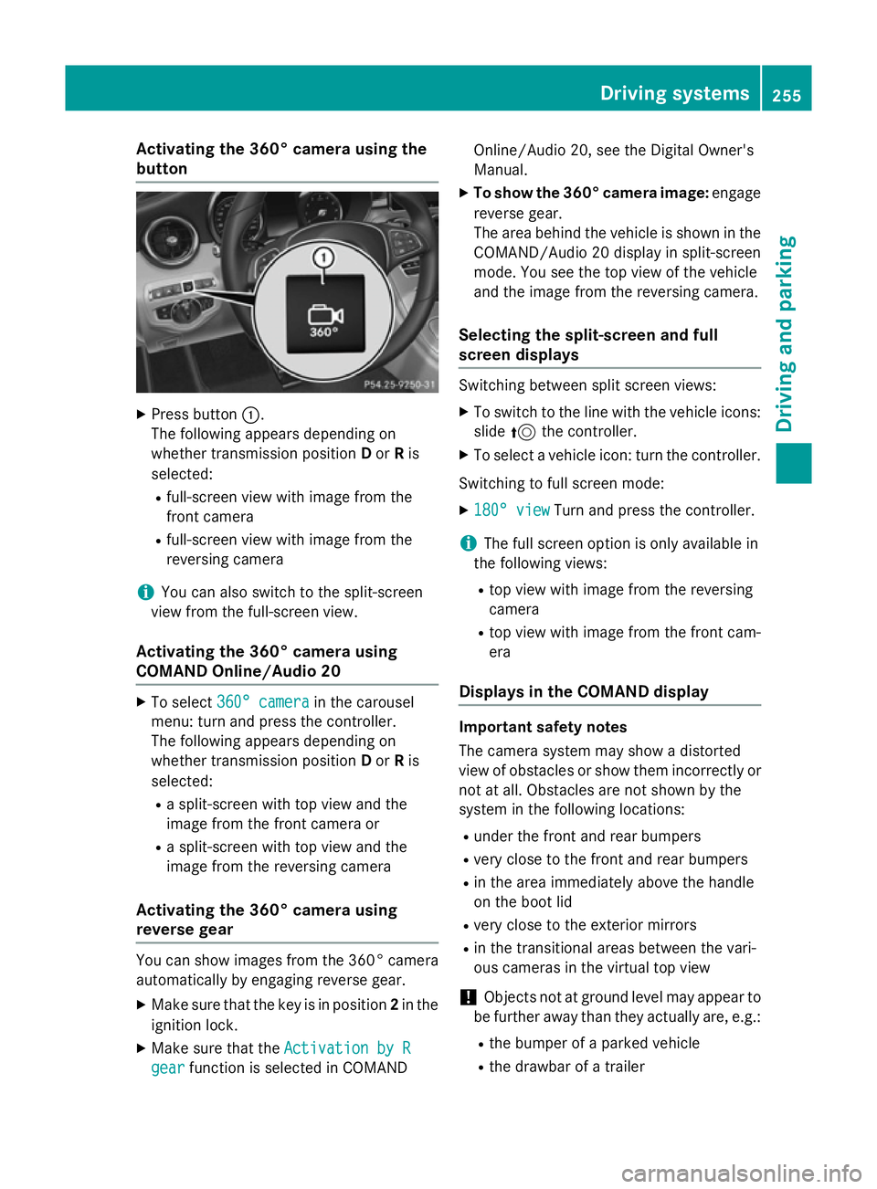
Activating the 360° camera using the
button X
Press button :.
The following appears depending on
whether transmission position Dor Ris
selected:
R full-screen view with image from the
front camera
R full-screen view with image from the
reversing camera
i You can also switch to the split-screen
view from the full-screen view.
Activating the 360° camera using
COMAND Online/Audio 20 X
To select 360° camera 360° camera in the carousel
menu: turn and press the controller.
The following appears depending on
whether transmission position Dor Ris
selected:
R a split-screen with top view and the
image from the front camera or
R a split-screen with top view and the
image from the reversing camera
Activating the 360° camera using
reverse gear You can show images from the 360° camera
automatically by engaging reverse gear.
X Make sure that the key is in position 2in the
ignition lock.
X Make sure that the Activation by R Activation by R
gear
gear function is selected in COMAND Online/Audio 20, see the Digital Owner's
Manual.
X To show the 360° camera image: engage
reverse gear.
The area behind the vehicle is shown in the COMAND/Audio 20 display in split-screen
mode. You see the top view of the vehicle
and the image from the reversing camera.
Selecting the split-screen and full
screen displays Switching between split screen views:
X To switch to the line with the vehicle icons:
slide 5the controller.
X To select a vehicle icon: turn the controller.
Switching to full screen mode:
X 180° view
180° view Turn and press the controller.
i The full screen option is only available in
the following views:
R top view with image from the reversing
camera
R top view with image from the front cam-
era
Displays in the COMAND display Important safety notes
The camera system may show a distorted
view of obstacles or show them incorrectly or
not at all. Obstacles are not shown by the
system in the following locations:
R under the front and rear bumpers
R very close to the front and rear bumpers
R in the area immediately above the handle
on the boot lid
R very close to the exterior mirrors
R in the transitional areas between the vari-
ous cameras in the virtual top view
! Objects not at ground level may appear to
be further away than they actually are, e.g.:
R the bumper of a parked vehicle
R the drawbar of a trailer Driving systems
255Driving and parking Z
Page 267 of 489
the case if there are vehicles at the edge of
their lane nearest your vehicle.
Due to the nature of the system:
R warnings may be issued in error when driv-
ing close to crash barriers or similar solid
lane borders
R warnings may be interrupted when driving
alongside long vehicles, for example lor-
ries, for a prolonged time
The two radar sensors for Blind Spot Assist
are integrated into the sides of the rear
bumper. Make sure that the bumper is free of dirt, ice or slush in the vicinity of the sensors.
The sensors must not be covered, for exam-
ple by cycle racks or overhanging loads. Fol-
lowing a severe impact or in the event of dam- age to the bumpers, have the function of the
sensors checked at a qualified specialist
workshop. Blind Spot Assist may otherwise
not work properly.
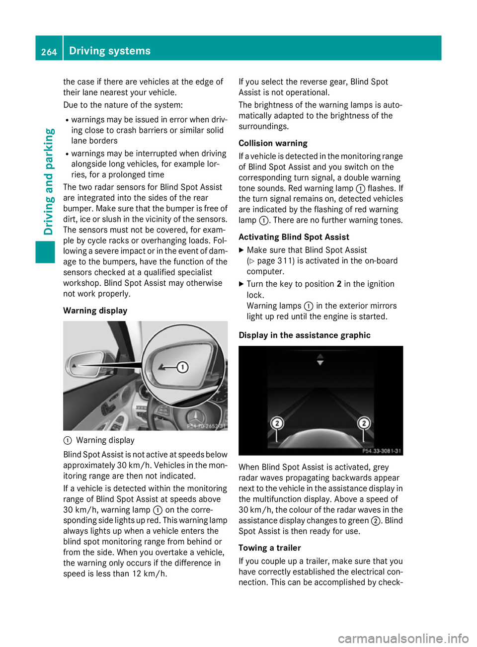
Warning display :
Warning display
Blind Spot Assist is not active at speeds below approximately 30 km/h. Vehicles in the mon-itoring range are then not indicated.
If a vehicle is detected within the monitoring
range of Blind Spot Assist at speeds above
30 km/h, warning lamp :on the corre-
sponding side lights up red. This warning lamp
always lights up when a vehicle enters the
blind spot monitoring range from behind or
from the side. When you overtake a vehicle,
the warning only occurs if the difference in
speed is less than 12 km/h. If you select the reverse gear, Blind Spot
Assist is not operational.
The brightness of the warning lamps is auto-
matically adapted to the brightness of the
surroundings.
Collision warning
If a vehicle is detected in the monitoring range
of Blind Spot Assist and you switch on the
corresponding turn signal, a double warning
tone sounds. Red warning lamp :flashes. If
the turn signal remains on, detected vehicles
are indicated by the flashing of red warning
lamp :. There are no further warning tones.
Activating Blind Spot Assist X Make sure that Blind Spot Assist
(Y page 311) is activated in the on-board
computer.
X Turn the key to position 2in the ignition
lock.
Warning lamps :in the exterior mirrors
light up red until the engine is started.
Display in the assistance graphic When Blind Spot Assist is activated, grey
radar waves propagating backwards appear
next to the vehicle in the assistance display in
the multifunction display. Above a speed of
30 km/h, the colour of the radar waves in the
assistance display changes to green ;. Blind
Spot Assist is then ready for use.
Towing a trailer
If you couple up a trailer, make sure that you
have correctly established the electrical con- nection. This can be accomplished by check- 264
Driving systemsDriving an
d parking
Page 272 of 489
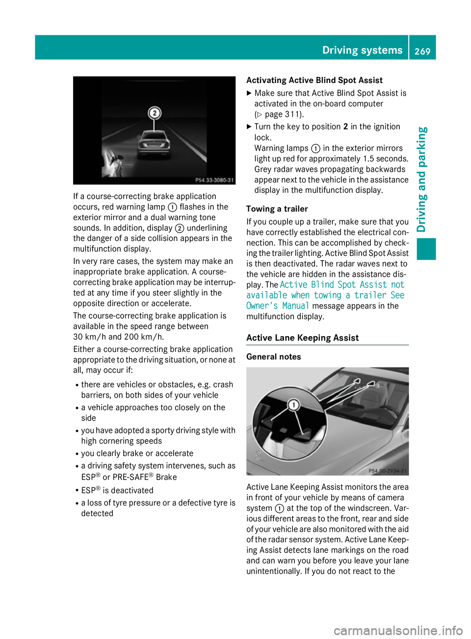
If a course-correcting brake application
occurs, red warning lamp :flashes in the
exterior mirror and a dual warning tone
sounds. In addition, display ;underlining
the danger of a side collision appears in the
multifunction display.
In very rare cases, the system may make an
inappropriate brake application. A course-
correcting brake application may be interrup-
ted at any time if you steer slightly in the
opposite direction or accelerate.
The course-correcting brake application is
available in the speed range between
30 km/h and 200 km/h.
Either a course-correcting brake application
appropriate to the driving situation, or none at all, may occur if:
R there are vehicles or obstacles, e.g. crash
barriers, on both sides of your vehicle
R a vehicle approaches too closely on the
side
R you have adopted a sporty driving style with
high cornering speeds
R you clearly brake or accelerate
R a driving safety system intervenes, such as
ESP ®
or PRE-SAFE ®
Brake
R ESP ®
is deactivated
R a loss of tyre pressure or a defective tyre is
detected Activating Active Blind Spot Assist
X Make sure that Active Blind Spot Assist is
activated in the on-board computer
(Y page 311).
X Turn the key to position 2in the ignition
lock.
Warning lamps :in the exterior mirrors
light up red for approximately 1.5 seconds. Grey radar waves propagating backwards
appear next to the vehicle in the assistance
display in the multifunction display.
Towing a trailer
If you couple up a trailer, make sure that you have correctly established the electrical con-
nection. This can be accomplished by check- ing the trailer lighting. Active Blind Spot Assist
is then deactivated. The radar waves next to
the vehicle are hidden in the assistance dis-
play. The Active
Active Blind BlindSpot
SpotAssist
Assist not
not
available
available when
whentowing
towing a
atrailer
trailer See
See
Owner's Manual
Owner's Manual message appears in the
multifunction display.
Active Lane Keeping Assist General notes
Active Lane Keeping Assist monitors the area
in front of your vehicle by means of camera
system :at the top of the windscreen. Var-
ious different areas to the front, rear and side
of your vehicle are also monitored with the aid
of the radar sensor system. Active Lane Keep-
ing Assist detects lane markings on the road
and can warn you before you leave your lane
unintentionally. If you do not react to the Driving systems
269Driving and parking Z
Page 280 of 489
?
High-voltage battery
A Energy flow
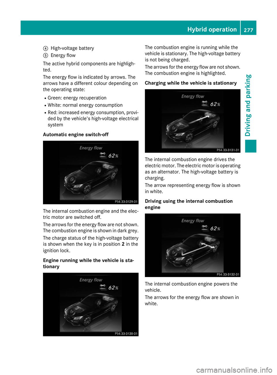
The active hybrid components are highligh-
ted.
The energy flow is indicated by arrows. The
arrows have a different colour depending on
the operating state:
R Green: energy recuperation
R White: normal energy consumption
R Red: increased energy consumption, provi-
ded by the vehicle's high-voltage electrical
system
Automatic engine switch-off The internal combustion engine and the elec-
tric motor are switched off.
The arrows for the energy flow are not shown.
The combustion engine is shown in dark grey.
The charge status of the high-voltage battery is shown when the key is in position 2in the
ignition lock.
Engine running while the vehicle is sta-
tionary The combustion engine is running while the
vehicle is stationary. The high-voltage battery
is not being charged.
The arrows for the energy flow are not shown. The combustion engine is highlighted.
Charging while the vehicle is stationary The internal combustion engine drives the
electric motor. The electric motor is operating
as an alternator. The high-voltage battery is
charging.
The arrow representing energy flow is shown in white.
Driving using the internal combustion
engine The internal combustion engine powers the
vehicle.
The arrows for the energy flow are shown in
white. Hybrid operation
277Driving and parking Z
Page 282 of 489
Driving using the electric motor and
charging the high-voltage battery The electric motor is being operated as an
alternator, e.g. in overrun mode and when
braking. The kinetic energy of the vehicle is
converted into electrical energy. The high-
voltage battery is charging.
The arrows for the energy flow are shown in
green. The combustion engine is shown in
dark grey.
Displaying the total range The approximate range is based on the cur-
rent driving style.
X Use Ñ on the steering wheel to call up
the list of menus.
X Press the :or9 button on the steer-
ing wheel to select the Trip
Trip menu.
X Confirm by pressing aon the steering
wheel.
X Press :or9 to select the approxi-
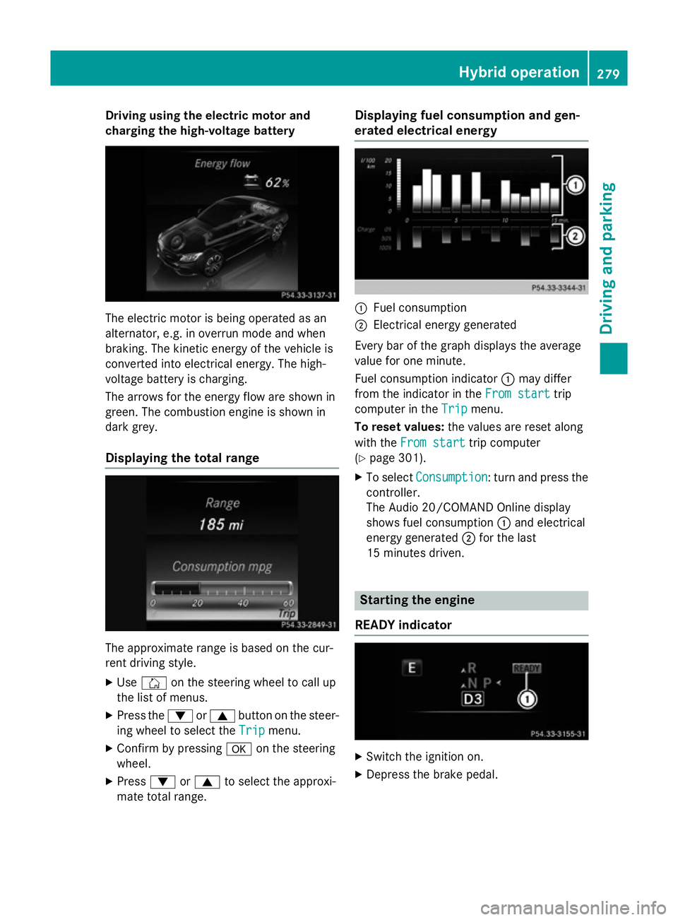
mate total range. Displaying fuel consumption and gen-
erated electrical energy :
Fuel consumption
; Electrical energy generated
Every bar of the graph displays the average
value for one minute.
Fuel consumption indicator :may differ
from the indicator in the From start From starttrip
computer in the Trip
Tripmenu.
To reset values: the values are reset along
with the From start
From start trip computer
(Y page 301).
X To select Consumption
Consumption: turn and press the
controller.
The Audio 20/COMAND Online display
shows fuel consumption :and electrical
energy generated ;for the last
15 minutes driven. Starting the engine
READY indicator X
Switch the ignition on.
X Depress the brake pedal. Hybrid operation
279Driving and parking Z