2014 Lancia Voyager ECU
[x] Cancel search: ECUPage 157 of 364

the ash receiver, align the receiver so
the thumb grip on the lid is facing
rearward. Press the ash receiver into
either of the cup wells to secure. Pull
upward on the ash receiver to remove
for cleaning and/or storage.
The left rear trim panel cupholder is
designed to accommodate a second
ash receiver, if desired.
POWER INVERTER (for
versions/markets, where
provided)
A 110 Volt, 150 Watt inverter outlet
(for versions/markets, where pro-
vided) converts DC current to AC cur-
rent, and is located on the left rear
trim panel immediately behind the
second row left passenger seat.The power inverter switch is located
on the instrument panel below the
climate controls.
To turn on the power outlet, press the
switch once. Press the switch a second
time to turn the power outlet off.
This outlet can power cellular phones,
electronics and other low power de-
vices requiring power up to 150
Watts. Certain high-end video games
will exceed this power limit, as will
most power tools.
The power inverter is designed with
built-in overload protection. If the
power rating of 150 Watts is ex-
ceeded, the power inverter will auto-
matically shut down. Once the electri-
cal device has been removed from the
outlet the inverter should automati-
cally reset. If the power rating exceeds
approximately 170 Watts, the power
inverter may have to be reset manu-
ally. To reset the inverter manually
press the power inverter button OFF
and ON. To avoid overloading the cir-
cuit, check the power ratings on elec-
trical devices prior to using the in-
verter.
CUPHOLDERS
There are cupholders located
throughout the interior. All liners are
removable for cleaning. Pull the flex-
ible liner from the cupholder drawer
or tray starting at one edge for easy
removal. Refer to “Cleaning The In-
strument Panel Cupholders” in
“Maintaining Your Vehicle” for fur-
ther information.
INSTRUMENT PANEL
CUPHOLDERS
The instrument panel cupholders are
located in a pull-out drawer just
above the lower storage bin.
Pull the drawer out firmly until it
stops, and place the container to be
held in either one of the cupholder
Power Inverter Outlet
Front Cupholders
151
Page 159 of 364

Two outboard mesh pockets are on
intermediate seating. The mesh pock-
ets are flexible enough to hold juice
boxes, toys, games or MP3 players,
etc.
SMOKER'S PACKAGE KIT
(for versions/markets,
where provided)
With the optional authorized dealer-
installed Smoker's Package Kit, a re-
movable ash receiver is inserted into
one of the two cupholders in the cen-
ter front instrument panel. To install
the ash receiver, align the receiver so
the thumb grip on the lid is facing
rearward. Press the ash receiver into
either of the cup wells to secure. Pull
upward on the ash receiver to remove
for cleaning and/or storage.
The left rear trim panel cupholder is
designed to accommodate a second
ash receiver, if desired.
STORAGE
GLOVE COMPARTMENTS
Upper and lower glove compartments
are located on the passenger side of
the instrument panel.
Upper Glove Compartment
To open the upper compartment,
press in on the button, located on the
left side of the upper door. The door
will automatically open.
To close the compartment door, push
downward on the door’s surface to
latch the door closed.Lower Glove Compartment
To open the lower compartment pull
out on the release handle.
DOOR TRIM PANEL
STORAGE
Front Door Storage
Both interior front door panels have
multiple pockets for storage.
WARNING!
If containers of hot liquid are
placed in the bottle holder, they can
spill when the door is closed, burn-
ing the occupants. Be careful when
closing the doors to avoid injury.
Upper Compartment
Lower Compartment
153
Page 161 of 364

STORAGE BIN SAFETY
WARNING
Carefully follow these warnings to
help prevent personal injury or dam-
age to your vehicle:
WARNING!
Always close the storage bin cov-ers when your vehicle is unat-
tended.
Do not allow children to have ac- cess to the second row seat stor-
age bins. Once in the storage bin,
young children may not be able to
escape. If trapped in the storage
bin, children can die from suffo-
cation or heat stroke.
In a collision, serious injury could result if the seat storage bin cov-
ers are not properly latched.
Do not drive the vehicle with the storage bin covers open. Keep the
storage bin covers closed and
latched while the vehicle is in mo-
tion.
(Continued)
WARNING!(Continued)
Do not operate the storage bincovers while the vehicle is in mo-
tion.
Do not use a storage bin latch as a tie down.
CAUTION!
The storage bin cover must be flat
and locked to avoid damage from
contact with the front seat tracks,
which have minimal clearance to
the cover.
NOTE: In the event of an indi-
vidual being locked inside the
storage bin, the storage bin cover
can be opened from inside of the
bin by pushing on the glow-in-the-
dark lever attached to the storage
bin cover latching mechanism. Seat Storage Bin Cover
Emergency Release Lever
As a security measure, the Seat Stor-
age Bin Cover has an Emergency Re-
lease Lever built into the latching
mechanism.
NOTE: In the event of an indi-
vidual being locked inside the
storage bin, the storage bin cover
can be opened from inside of the
bin by pushing on the glow-in-the-
dark lever attached to the storage
bin cover latching mechanism.
Storage Bin Cover Emergency Release
Lever
155
Page 168 of 364

CAUTION!
Use care when removing and han-
dling the crossbars to prevent dam-
age to the vehicle.
Bend the crossbar supports at each
end, taking care to keep hand clear of
pivoting joint. Slide the thumb screw
down. Then, position the crossbars across
the roof.
NOTE: The crossbars are identi-
cal and can be placed in any two of
the three deploy positions.
Make sure the directional arrows on
the crossbars align with the direc-
tional arrows on the side rails. Set the
crossbars into the deployed positions.Once the crossbars are set into posi-
tion, tighten the thumb screws com-
pletely.
Stowing the Crossbars
Reverse the procedure to stow the
crossbars, again, taking care to keep
hand clear of pivoting joint. Crossbars
are identical and can be stowed in
either rail nest. Once the crossbars are
stowed, tighten the thumb screws
completely.
NOTE: Load should always be se-
cured to crossbars first, with rail
tie down loops used as additional
securing points if needed. Tie
loops are intended as supplemen-
tary tie down points only. Do not
use ratcheting mechanisms with
the tie loops.
Stowed Position
Deployed Position
Deploy Positions – Choose Two Of
Three
Crossbar To Side Rail Installation
Tightening Crossbar
162
Page 169 of 364

CAUTION!
Check deployed crossbars fre-quently and retighten thumb
screws as necessary.
To avoid damage to the roof rack and vehicle, do not exceed the
maximum roof rack load capacity
of 68 kg. Always distribute heavy
loads as evenly as possible and
secure the load appropriately.
To prevent damage to the roof of your vehicle, DO NOT carry any
loads on the roof rack without the
crossbars deployed.
(Continued)
CAUTION!(Continued)
The load should be secured andplaced on top of the crossbars, not
directly on the roof. If it is neces-
sary to place the load on the roof,
place a blanket or other protec-
tive layer between the load and
the roof surface.
Long loads which extend over the windshield, such as wood panels
or surfboards, or loads with large
frontal area should be secured to
both the front and rear of the
vehicle.
Travel at reduced speeds and turn corners carefully when carrying
large or heavy loads on the roof
rack. Wind forces, due to natural
causes or nearby truck traffic,
can add sudden upward lift to a
load. This is especially true on
large flat loads and may result in
damage to the cargo or your ve-
hicle.
WARNING!
Cargo must be securely tied before
driving your vehicle. Improperly
secured loads can fly off the vehicle,
particularly at high speeds, result-
ing in personal injury or property
damage. Follow the roof rack cau-
tions when carrying cargo on your
roof rack.
HEADLIGHT WASHER
(for versions/markets,
where provided)
The multifunction lever operates the
headlight washers when the ignition
switch is in the ON position and the
headlights are turned on. The multi-
function lever is located on the left
side of the steering column.
To use the headlight washers, push
the multifunction lever inward (to-
ward the steering column) to the sec-
ond detent and release it. The head-
light washers will spray a timed high-
pressure spray of washer fluid onto
each headlight lens. In addition, the
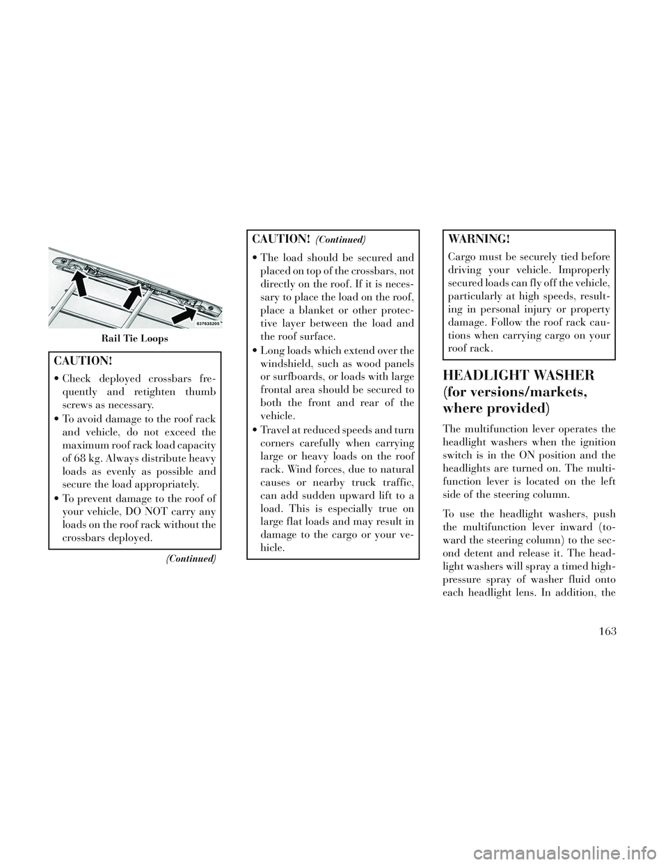
Rail Tie Loops
163
Page 182 of 364

11. Electronic Stability Control
(ESC) OFF Indicator Light (for
versions/markets, where provided)This light indicates the
Electronic Stability Control
(ESC) is off.
12. Speedometer
Indicates vehicle speed.
13. Fuel Door Reminder The arrow in this symbol is
a reminder that the Fuel
Filler Door is located on the
left side of the vehicle.
14. Fuel Gauge
The pointer shows the level of fuel in
the fuel tank when the ignition switch
is in the ON/RUN position.
15. Air Bag Warning Light
This light will turn on for
four to eight seconds as a
bulb check when the igni-
tion switch is first turned to
ON/RUN. If the light is either not on
during starting, stays on, or turns on while driving, have the system in-
spected at an authorized dealer as
soon as possible. Refer to “Occupant
Restraints” in “Things To Know Be-
fore Starting Your Vehicle” for further
information.
16. Shift Lever Indicator
The Shift Lever Indicator is self-
contained within the instrument clus-
ter. It displays the gear position of the
automatic transmission.
NOTE:
You must apply the brakes be-
fore shifting from PARK.
The highest available transmis- sion gear is displayed in the
lower right corner of the Elec-
tronic Vehicle Information Cen-
ter (EVIC) whenever the Elec-
tronic Range Select (ERS)
feature is active. Use the +/- se-
lector on the shift lever to acti-
vate ERS (for versions/markets,
where provided). Refer to “Auto-
matic Transmission” in “Start-
ing And Operating” for further
information. 17. Vehicle Security Light (for
versions/markets, where provided)
This light will flash at a fast
rate for approximately 15
seconds, when the vehicle
security alarm is arming,
and then will flash slowly until the
vehicle is disarmed.
18. Brake Warning Light
This light monitors various
brake functions, including
brake fluid level and parking brake
application. If the brake light turns on
it may indicate that the parking brake
is applied, that the brake fluid level is
low, or that there is a problem with the
anti-lock brake system reservoir.
If the light remains on when the park-
ing brake has been disengaged, and
the fluid level is at the full mark on the
master cylinder reservoir, it indicates
a possible brake hydraulic system
malfunction or that a problem with
the Brake Booster has been detected
by the Anti-Lock Brake System (ABS)
/ Electronic Stability Control (ESC)
system. In this case, the light will re-
main on until the condition has been
176
Page 238 of 364

ignition switch to the LOCK position,
wait 10 to 15 seconds, then repeat the
“Normal Starting” procedure.
KEYLESS ENTER-N-GO™
(for versions/markets,
where provided)
This feature allows
the driver to oper-
ate the ignition
switch with the
push of a button,
as long as the EN-
GINE START/
STOP button is installed and the Re-
mote Keyless Entry (RKE)
transmitter is in the passenger
compartment.
Installing And Removing The
ENGINE START/STOP Button
Installing The Button
1. Remove the key fob from the igni-
tion switch.
2. Insert the ENGINE START/STOP
button into the ignition switch with
the lettering facing up and readable. 3. Press firmly on the center of the
button to secure it into position.
Removing The Button
1. The ENGINE START/STOP but-
ton can be removed from the ignition
switch for key fob use.
2. Insert the metal part of the emer-
gency key under the chrome bezel at
the 6 o’clock position and gently pry
the button loose.
NOTE: The ENGINE START/
STOP button should only be re-
moved or inserted with the ignition
in the OFF position (OFF position
for Keyless Enter-N-Go™).
NORMAL STARTING —
GASOLINE ENGINE
Using The ENGINE START/STOP
Button
NOTE: Normal starting of either
a cold or a warm engine is ob-
tained without pumping or press-
ing the accelerator pedal.
To start the engine, the transmission
must be in PARK or NEUTRAL. Press
and hold the brake pedal while press-
ing the ENGINE START/STOP but-
ton once. The system takes over and
attempts to start the vehicle. If the
vehicle fails to start, the starter will
disengage automatically after 10 sec-
onds. If you wish to stop the cranking
of the engine prior to the engine start-
ing, press the button again.
To Turn Off The Engine Using
ENGINE START/STOP Button
1. Place the shift lever in PARK, then
press and release the ENGINE
START/STOP button.
2. The ignition switch will return to
the OFF position.
3. If the shift lever is not in PARK and
the vehicle speed is above 8 km/h, the
ENGINE START/STOP button must
be held for two seconds before the
engine shuts off. The ignition switch
position will remain in the ACC posi-
tion until the shift lever is in PARK
and the button is pressed twice to the
OFF position. If the shift lever is not
in PARK and the ENGINE START/
STOP button is pressed once, the
232
Page 242 of 364

AUTOMATIC
TRANSMISSION
CAUTION!
Damage to the transmission may
occur if the following precautions
are not observed:
Shift into PARK only after thevehicle has come to a complete
stop.
Shift into or out of REVERSE only after the vehicle has come to
a complete stop and the engine is
at idle speed.
Do not shift between PARK, RE- VERSE, NEUTRAL, or DRIVE
when the engine is above idle
speed.
Before shifting into any gear, make sure your foot is firmly
pressing the brake pedal.
NOTE: You must press and hold
the brake pedal while shifting out
of PARK.
WARNING!
It is dangerous to shift out of PARK or NEUTRAL if the engine
speed is higher than idle speed. If
your foot is not firmly pressing
the brake pedal, the vehicle could
accelerate quickly forward or in
reverse. You could lose control of
the vehicle and hit someone or
something. Only shift into gear
when the engine is idling nor-
mally and your foot is firmly
pressing the brake pedal.
Unintended movement of a ve- hicle could injure those in or near
the vehicle. As with all vehicles,
you should never exit a vehicle
while the engine is running. Be-
fore exiting a vehicle, always ap-
ply the parking brake, shift the
transmission into PARK, turn the
engine OFF, and remove the key
fob. When the ignition is in the
LOCK position, the transmission
is locked in PARK, securing the
vehicle against unwanted move-
ment.
(Continued)
WARNING!(Continued)
When leaving the vehicle, alwaysremove the key fob and lock your
vehicle.
Never leave children alone in a vehicle, or with access to an un-
locked vehicle. Allowing children
to be in a vehicle unattended is
dangerous for a number of rea-
sons. A child or others could be
seriously or fatally injured. Chil-
dren should be warned not to
touch the parking brake, brake
pedal or the shift lever.
Do not leave the key fob in or near the vehicle (or in a location acces-
sible to children), and do not
leave the ignition (in a vehicle
equipped with Keyless Enter-N-
Go™) in the ACC or ON/RUN
position. A child could operate
power windows, other controls, or
move the vehicle.
236