Page 228 of 364

Controlling The Rear Climate
Controls From The Front ATC
Panel
The Three-Zone ATC system allows
for adjustment of the rear climate
controls from the front ATC panel.
To change the rear system settings:
Press "REAR" button to change con-
trol to rear control mode, Rear dis-
play (below) will appear. Control
functions now operate rear system.
To return to Front screen, press"REAR" button again, or it will
revert to the Front screen after six
seconds.
1. Mode Display
This display shows the current Mode
selection. 2. Rear Temperature Display
This display shows the temperature
setting for the rear seat occupants.
3. Blower Control Display
This display shows the current Blower
speed selection.
4. Rear Auto Indicator
This indicates when the system is in
Rear Auto mode.
Rear Mode Control
Auto Mode
The rear system automatically main-
tains the correct mode and comfort
level desired by the rear seat occu-
pants.
Headliner Mode
Air comes from the outlets in
the headliner. Each of these
outlets can be individually adjusted to
direct the flow of air. Moving the air
vanes of the outlets to one side will
shut off the airflow. Bi-Level Mode
Air comes from both the head-
liner outlets and the floor
outlets.
NOTE: In many temperature po-
sitions, the BI-LEVEL mode is de-
signed to provide cooler air out of
the headliner outlets and warmer
air from the floor outlets.
Floor Mode Air comes from the floor
outlets.
Rear Automatic Temperature
Control (ATC) (for versions/
markets, where provided)
The rear ATC system has floor air
outlets at the rear of the right side
sliding door, and overhead outlets at
each outboard rear seating position.
The system provides heated air
through the floor outlets or cool, de-
humidified air through the headliner
outlets.
The rear system temperature control
is on the front ATC panel located on
the instrument panel.
Front ATC Panel Rear Control Display
222
Page 333 of 364
FUSES/TIPM
Cavity Cartridge Fuse Mini-Fuse Description J22 25 Amp Natural — Sunroof ModuleM1 — 15 Amp Blue Rear Center Brake Lamp/Brake Switch
M2 — 20 Amp Yellow Trailer Lighting/Fog Lamps
M3 — 20 Amp Yellow Front/Rear Axle Locker/Vacuum Pump Motor
M4 — 10 Amp Red Trailer Tow
M5 — 25 Amp Natural Inverter
M6 — 20 Amp Yellow Power Outlet #1 (ACC), Rain Sensor
M7 — 20 Amp Yellow Power Outlet #2 (BATT/ACC SELECT)
M8 — 20 Amp Yellow Front Heated Seat (for versions/markets, where provided)
M9 — 20 Amp Yellow Rear Heated Seat (for versions/markets, where provided)
M10 —15 Amp Blue Ignition Off Draw — Video System, DVD,
Hands-Free Module, Vanity Lamp, StreamingVideo Module
M11 —10 Amp Red Ignition Off Draw – Climate Control System
M12 —30 Amp Green Amplifier (AMP)/Radio
M13 —20 Amp Yellow Ignition Off Draw— Instrument Cluster, SI-
REN, Clock Module, Multi-Function ControlSwitch/ITM
M14 —20 Amp Yellow Spare Fuse
327
Page 335 of 364

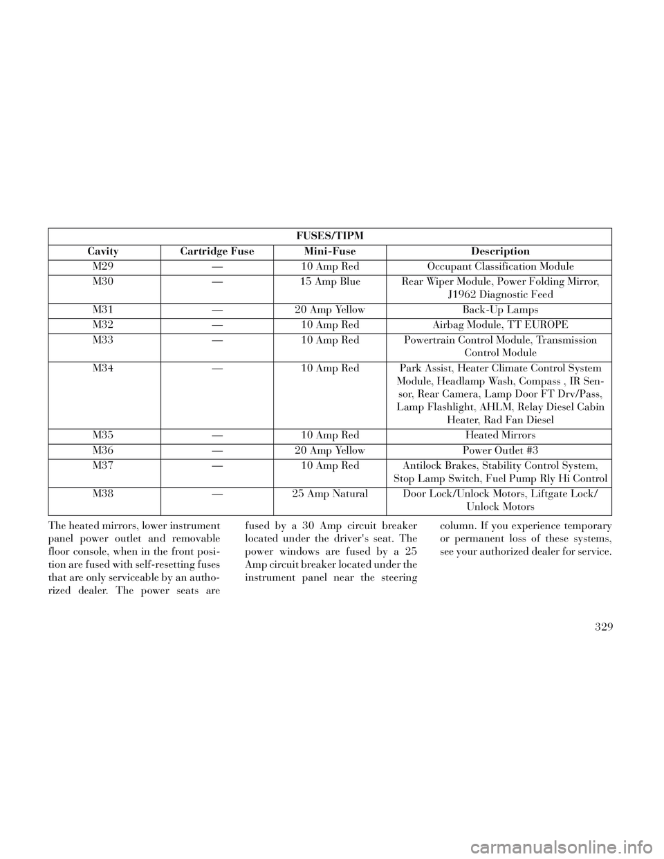
FUSES/TIPM
Cavity Cartridge Fuse Mini-Fuse Description M29 — 10 Amp Red Occupant Classification Module
M30 — 15 Amp Blue Rear Wiper Module, Power Folding Mirror, J1962 Diagnostic Feed
M31 — 20 Amp Yellow Back-Up Lamps
M32 — 10 Amp Red Airbag Module, TT EUROPE
M33 — 10 Amp Red Powertrain Control Module, Transmission Control Module
M34 — 10 Amp Red Park Assist, Heater Climate Control System Module, Headlamp Wash, Compass , IR Sen-sor, Rear Camera, Lamp Door FT Drv/Pass,
Lamp Flashlight, AHLM, Relay Diesel Cabin Heater, Rad Fan Diesel
M35 — 10 Amp Red Heated Mirrors
M36 — 20 Amp Yellow Power Outlet #3
M37 — 10 Amp Red Antilock Brakes, Stability Control System, Stop Lamp Switch, Fuel Pump Rly Hi Control
M38 — 25 Amp Natural Door Lock/Unlock Motors, Liftgate Lock/ Unlock Motors
The heated mirrors, lower instrument
panel power outlet and removable
floor console, when in the front posi-
tion are fused with self-resetting fuses
that are only serviceable by an autho-
rized dealer. The power seats are fused by a 30 Amp circuit breaker
located under the driver's seat. The
power windows are fused by a 25
Amp circuit breaker located under the
instrument panel near the steering
column. If you experience temporary
or permanent loss of these systems,
see your authorized dealer for service.
329
Page 355 of 364

Cellular Phone...........89, 218
Center High Mounted StopLight
..................333
Chains, Tire.............. .265
Changing A Flat Tire.........287
Chart, Tire Sizing............253
Check Engine Light (Malfunction
Indicator Light)
...........174
Checking Your Vehicle For Safety. .68
Checks, Safety...............68
Child Restraint..............56
Child Safety Locks............31
Clean Air Gasoline...........274
CleaningWheels
................322
Climate Control.............219
Coat Hook................156
Coin Holder.............. .156
Cold Weather Operation.......233
Compact Disc (CD) Maintenance. .218
Compact Spare Tire..........262
Compass..................186
Compass Calibration..........187
Compass Variance...........187
Computer, Trip/Travel.........185
Connector
UCI
................. .193
Universal Consumer Interface
(UCI)
.................193
Conserving Fuel.............184
Console..................156
Console, Floor..............156
Console, Overhead...........144
Console, Removable..........159
Cool Down, Turbo...........235
Cooling System.............315
Adding Coolant (Antifreeze). .317
Coolant Capacity..........333
Coolant Level........315, 317
Disposal of Used Coolant. . . .317
Drain, Flush, and Refill.....316
Inspection..............317
Points to Remember.......318
Selection of Coolant
(Antifreeze)
......316, 333, 334
Corrosion Protection..........321
Cupholders............151, 324
Data Recorder, Event..........55
Defroster, Windshield..........69
Diagnostic System, Onboard.....307
Diesel Fuel.............275, 334
Diesel Fuel Requirements.......275
Dipsticks
Automatic Transaxle
.......320
Oil (Engine).............308
Power Steering...........245
Disabled Vehicle Towing.......299
DisposalAntifreeze (Engine Coolant)
. .317
Door Locks.................22
Door Locks, Automatic.........24
DrivingThrough Flowing, Rising, or
Shallow Standing Water
.....243
Driving to Achieve Maximum Fuel
Economy
................184
Electrical Power Outlets.......149
Electric Remote Mirrors.........83
Electronic Brake Control System. .248
Brake Assist System........249
Electronic Speed Control (CruiseControl)
................136
Electronic Stability Control(ESC)
..................249
Electronic Vehicle Information Center(EVIC)
.............143, 178
Emergency, In Case ofHazard Warning Flasher
.....286
Jacking............287, 291
Jump Starting............296
Overheating.............286
Engine.................. .306
Air Cleaner.............309
Break-In Recommendations. . .68
Checking Oil Level........308
349