Page 548 of 665

6-14
What to do in an emergency
10. Loosen the lug nuts with the
wheel lug nut wrench and
remove them with your fingers.
Remove the wheel from the
studs and lay it flat on the ground
out of the way. Remove any dirt
or debris from the studs, mount-
ing surfaces, and wheel.
11. Install the spare tire onto the
studs of the hub.
12. Tighten the lug nuts with your fin-
gers onto the studs with the
smaller end of the lug nuts clos-
est to the wheel.
13. Lower the vehicle to the ground
by turning the jack handle coun-
terclockwise.
14. Use the wheel lug nut wrench to
tighten the lug nuts in the order
shown. Double-check each lug
nut until they are tight. After
changing tires, we recommend
that an authorized HYUNDAI
dealer tighten the lug nuts to their
proper torque as soon as possi-
ble.The wheel lug nut should
be tightened to 9~11 kg.m
(65~79 lb.ft).
If you have a tire gauge, check the
tire pressure (see “Tires and Wheels”
in chapter 8 for tire pressure instruc-
tions.). If the pressure is lower or
higher than recommended, drive
slowly to the nearest service station
and adjust it to the recommended
pressure. Always reinstall the valve
cap after checking or adjusting tire
pressure. If the cap is not replaced,
air may leak from the tire. If you lose
a valve cap, buy another and install it
as soon as possible. After changing
tires, secure the flat tire and return
the jack and tools to their proper stor-
age locations.
Check the tire pressure as soon
as possible after installing a spare
tire. Adjust it to the recommended
pressure.
NOTICE
OLF064013
Page 554 of 665
6-20
What to do in an emergency
When towing your vehicle in an
emergency without wheel dollies:
1. Place the ignition switch in the
ACC position.
2. Place the shift lever in N (Neutral).
3. Release the parking brake.
Removable towing hook 1. Open the trunk, and remove the
towing hook from the tool case.
2. Remove the hole cover pressing
the lower part of the cover on the
front bumper.
3. Install the towing hook by turning it
clockwise into the hole until it is
fully secured.
4. Remove the towing hook and
install the cover after use.Failure to place the shift lever in
N (Neutral) may cause internal
damage to the transaxle.
CAUTION
OLF064024
OLF064025
OLF064027
■Front
■Rear
Page 587 of 665

7-30
Maintenance
ENGINE COOLANT
The high-pressure cooling system
has a reservoir filled with year-round
antifreeze coolant. The reservoir is
filled at the factory.
Check the antifreeze protection and
coolant concentration level at least
once a year, at the beginning of the
winter season, and before traveling
to a colder climate.
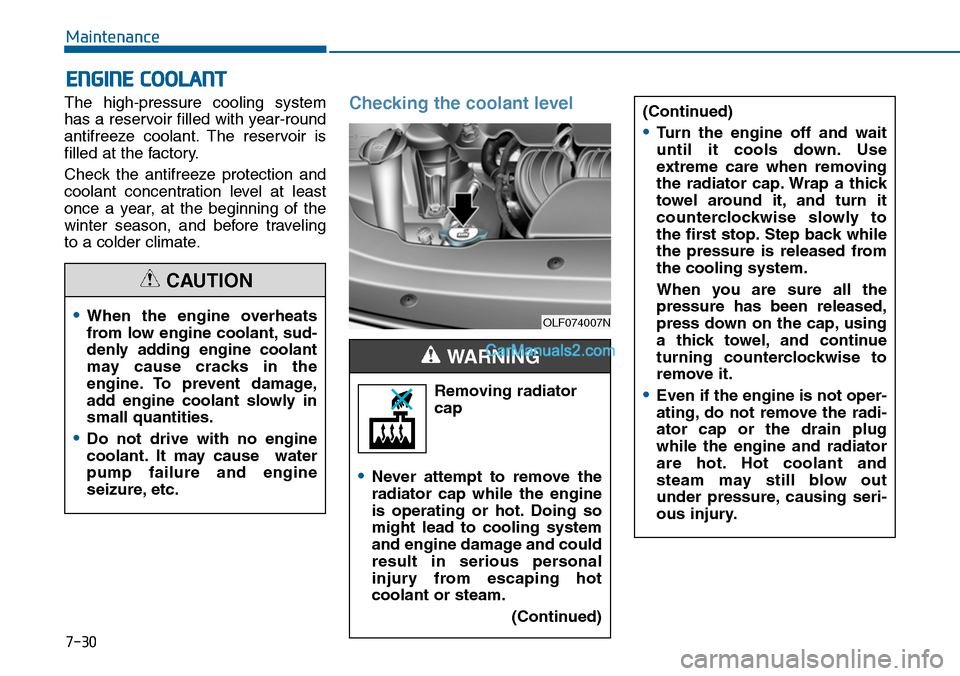
Checking the coolant level
Removing radiator
cap
•Never attempt to remove the
radiator cap while the engine
is operating or hot. Doing so
might lead to cooling system
and engine damage and could
result in serious personal
injury from escaping hot
coolant or steam.
(Continued)
WARNING
(Continued)
•Turn the engine off and wait
until it cools down. Use
extreme care when removing
the radiator cap. Wrap a thick
towel around it, and turn it
counterclockwise slowly to
the first stop. Step back while
the pressure is released from
the cooling system.
When you are sure all the
pressure has been released,
press down on the cap, using
a thick towel, and continue
turning counterclockwise to
remove it.
•Even if the engine is not oper-
ating, do not remove the radi-
ator cap or the drain plug
while the engine and radiator
are hot. Hot coolant and
steam may still blow out
under pressure, causing seri-
ous injury.
•When the engine overheats
from low engine coolant, sud-
denly adding engine coolant
may cause cracks in the
engine. To prevent damage,
add engine coolant slowly in
small quantities.
•Do not drive with no engine
coolant. It may cause water
pump failure and engine
seizure, etc.
CAUTION
OLF074007N
Page 618 of 665
7-61
7
Maintenance
Fuse switch
Always, place the fuse switch to the
ON position.
If you move the switch to the OFF
position, some items such as the
audio system and digital clock must
be reset and the smart key may not
work properly.
Information
If the fuse switch is OFF, the above
message will appear.
i
OLF074023
•Always place the fuse switch
in the ON position while driv-
ing the vehicle.
•Place the fuse switch in the
OFF position when the vehicle
is parked more than a month
to prevent battery discharge.
•Do not move the transportation
fuse switch repeatedly. The
fuse switch may be damaged.
CAUTION
OLF044148L
Page 622 of 665
7-65
7
Maintenance
Fuse NameSymbolFuse ratingCircuit Protected
SAFETYWINDOW LH 25ADriver Safety Power Window Module
P/SEAT PASS 30APassenger Seat Manual Switch
P/WDW LH 20APower Window Main Switch, Rear Power Window Module LH
P/WDW RH 25APower Window Main Switch, Rear Power Window Module RH Passenger Door Module,Passenger Power Window Switch
DR LOCK 20ADoor Lock Relay, Door Unlock Relay
S/HEATER FRT25AFront Air Ventilation Seat Module, Front Seat Warmer Module
BRAKE SWITCH 10AStop Lamp Switch, Immobilizer Module Smart Key Control Module
MODULE 8 7.5ABCM, Smart Key Control Module
SAFETY POWERWINDOW RH 25APassenger Safety Power Window Module
SMART KEY15ASmart Key Control Module
TRUNK 10ATrunk Lid Relay, Fuel Filler Door & Trunk Lid Switch
MODULE 7 10ADigital Clock, Driver/Passenger Door Module
Driver’s side fuse panel
Page 623 of 665

7-66
Maintenance
Fuse NameSymbolFuse ratingCircuit Protected
INTERIOR LAMP10AGlove Box Lamp, Ignition Key Ill. & Door Warning Switch, Front Vanity Lamp Switch LH/RH,Overhead Console Lamp, Room Lamp, Rear Personal Lamp LH/RH, Trunk Room Lamp,Driver/Passenger Smart Key Outside Handle Driver/Passenger Door Lamp
MEMORY 2 7.5AUIP Sensor
P/SEATDRV 30ADriver Seat Manual Switch, Driver IMS Module
CURTAIN 10ARear Curtain Module
CLUSTER 10AInstrument Cluster
MODULE 4 10AImmobilizer Module, Smart Key Control Module
MULTI MEDIA15AAudio, A/V & Navigation Head Unit
MEMORY 1 10ADriver/passenger Door Module, Instrument Cluster, Digital Clock, Driver IMS Module,Rain Sensor, Auto Light & Photo Sensor, ICM Relay Box(Outside Mirror Folding/UnfoldingMirror Relay), A/C Control Module, Rear Curtain Module, Data Link Connector, BCM
S/HEATER RR 25ARear Seat Warmer Module
SUN ROOF 2 20APanorama Sunroof Motor
MODULE 9 7.5AFront Air Ventilation Seat Module, Front Seat Warmer Module Rear Seat Warmer Module,Rear Curtain Module
Driver’s side fuse panel
Page 624 of 665
7
Maintenance
Fuse NameSymbolFuse ratingCircuit Protected
MDPS 17.5AMDPS Unit
MODULE 3 10ABCM, Sport Mode Switch, Stop Lamp Switch
STOP LAMP20AStop Signal Electronic Module
MODULE 1 MODULE17.5AKey Solenoid, Driver/Passenger Door Module
SUN ROOF 1 120APanorama Sunroof Motor
A/CON 7.5AA/C Control Module, E/R Junction Block (RLY. 3 - Blower Relay)
2MODULE 10AAMP, Power Outside Mirror Switch, Digital Clock, Audio, A/V & Navigation Head Unit, Smart Key Control Module, Overhead Console Lamp, BCM, E/R Junction Block (RLY. 5 - Power Outlet Relay)
A/BAG IND 7.5AInstrument Cluster
6MODULE 10A
Multipurpose Check Connector, A/C Control Module, A/V & Navigation Head Unit, Electro Chromic Mirror, Front Air Ventilation Seat Module, Front Seat Warmer Module, Rear Seat Warmer Module, Driver IMS Module, A/T Shift Lever IND, Auto Head Lamp Leveling Device Module, Head Lamp Leveling Device Actuator LH/RH
AMP25AAMP (JBL/MOBIS)
HTD STRG 15ABCM
Driver’s side fuse panel
7-67
Page 631 of 665

7-74
Maintenance
•Always handle them carefully, and
avoid scratches and abrasions. If
the bulbs are lit, avoid contact with
liquids.
•Never touch the glass with bare
hands. Residual oil may cause the
bulb to overheat and burst when lit.
•A bulb should be operated only
when installed in a headlamp.
•If a bulb becomes damaged or
cracked, replace it immediately
and carefully dispose of it.
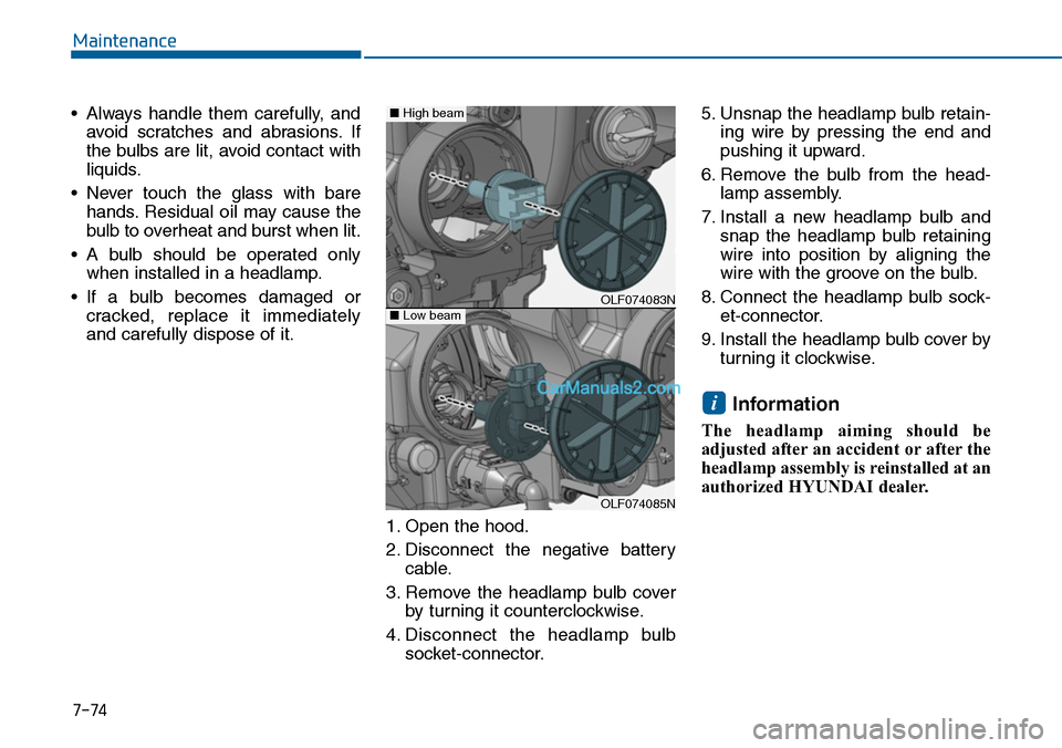
1. Open the hood.
2. Disconnect the negative battery
cable.
3. Remove the headlamp bulb cover
by turning it counterclockwise.
4. Disconnect the headlamp bulb
socket-connector.
5. Unsnap the headlamp bulb retain-
ing wire by pressing the end and
pushing it upward.
6. Remove the bulb from the head-
lamp assembly.
7. Install a new headlamp bulb and
snap the headlamp bulb retaining
wire into position by aligning the
wire with the groove on the bulb.
8. Connect the headlamp bulb sock-
et-connector.
9. Install the headlamp bulb cover by
turning it clockwise.
Information
The headlamp aiming should be
adjusted after an accident or after the
headlamp assembly is reinstalled at an
authorized HYUNDAI dealer.
i
OLF074083N
OLF074085N
■Low beam
■High beam