2014 Hyundai Equus tow
[x] Cancel search: towPage 174 of 479

485
Features of your vehicle
Check SCC System (if equipped)
• This warning message illuminates
if there is a malfunction with the
advanced smart cruise control sys-
tem. We recommend that the vehi-
cle be inspected by an authorized
HYUNDAI dealer.
❈For more details, refer to
"Advanced Smart Cruise Control
System" in chapter 5.
Check SCC Radar (if equipped)
• This warning message illuminates
if the radar of the advanced smart
cruise control system or its cover is
stained. Remove the stains with a
soft cloth.
❈For more details, refer to
"Advanced Smart Cruise Control
System" in chapter 5.
CAUTION - ECS Warning
Message
• If the Electronic Controlled
Suspension (ECS) Warning
Message illuminates when
there is no air in the suspen-
sion, the vehicle height will be
very low. In this case, do not
drive the vehicle to protect it
from the projections on the
surface of the ground. We rec-
ommend that the vehicle be
inspected by an authorized
HYUNDAI dealer.
• When towing the vehicle, you
should follow the instruction
in "Electronic Controlled
Suspension (ECS)" of chapter
5.
OVIEDI3954OVIEDI3955
Page 180 of 479

491
Features of your vehicle
Parking Brake & Brake
Fluid Warning Light
This warning light illuminates:
• Once you set the ignition switch or
Engine Start/Stop Button to the ON
position.
- It illuminates for approximately 3
seconds
- It remains on if the parking brake
is applied.
• When the parking brake is applied.
• When the brake fluid level in the
reservoir is low.
- If the warning light illuminates
with the parking brake released, it
indicates the brake fluid level in
reservoir is low.If the brake fluid level in the reservoir
is low:
1. Drive carefully to the nearest safe
location and stop your vehicle.
2. With the engine stopped, check
the brake fluid level immediately
and add fluid as required (For
more details, refer to "Brake Fluid"
in chapter 7). Then check all brake
components for fluid leaks. If any
leak on the brake system is still
found, the warning light remains
on, or the brakes do not operate
properly, do not drive the vehicle.
In this case, we recommend that
you have the vehicle towed to an
authorized HYUNDAI dealer and
inspected.Dual-diagonal braking system
Your vehicle is equipped with dual-
diagonal braking systems. This
means you still have braking on two
wheels even if one of the dual sys-
tems should fail.
With only one of the dual systems
working, more than normal pedal
travel and greater pedal pressure are
required to stop the vehicle.
Also, the vehicle will not stop in as
short a distance with only a portion
of the brake system working.
If the brakes fail while you are driv-
ing, shift to a lower gear for addition-
al engine braking and stop the vehi-
cle as soon as it is safe to do so.
Page 210 of 479

4121
Features of your vehicle
To flash the headlamp, pull the lever
towards you. It will return to the normal
(low beam) position when released.
The headlamp switch does not need
to be on to use this flashing feature.
Turn signals and lane change
signals
The engine start/stop button must be
on for the turn signals to function. To
turn on the turn signals, move the
lever up or down (A). The green
arrow indicators on the instrument
panel indicate which turn signal is
operating.
They will self-cancel after a turn is
completed. If the indicator continues
to flash after a turn, manually return
the lever to the OFF position.
To signal a lane change, move the
turn signal lever slightly and hold it in
position (B). The lever will return to
the OFF position when released.If an indicator stays on and does not
flash or if it flashes abnormally, one of
the turn signal bulbs may be burned
out and will require replacement.
One-touch turn signal
To activate an one-touch turn signal
move the turn signal lever slightly
and then release it. The lane change
signals will blink 3, 5 or 7 times.
You can set the number of operating
times. Refer to "LCD Display" in this
chapter.
✽NOTICE
If an indicator flash is abnormally
quick or slow, a bulb may be burned
out or have a poor electrical connec-
tion in the circuit.
ODM042248
ODM042250
Page 214 of 479

4125
Features of your vehicle
Windshield washers
In the OFF (O) position, pull the lever
gently toward you to spray washer
fluid on the windshield and to run the
wipers 1-3 cycles.
Use this function when the wind-
shield is dirty.
CAUTION
When the ignition switch is ON
and the windshield wiper switch
is placed in the AUTO mode, use
caution in the following situa-
tions to avoid any injury to the
hands or other parts of the body:
• Do not touch the upper end of
the windshield glass facing
the rain sensor.
• Do not wipe the upper end of
the windshield glass with a
damp or wet cloth.
• Do not put pressure on the
windshield glass.
CAUTION
When washing the vehicle, set
the wiper switch in the OFF
position to stop the auto wiper
operation.
The wiper may operate and be
damaged if the switch is set in
the AUTO mode while washing
the vehicle.
Do not remove the sensor cover
located on the upper end of the
passenger side windshield
glass. Damage to system parts
could occur and may not be cov-
ered by your vehicle warranty.
When starting the vehicle in
winter, set the wiper switch in
the OFF position. Otherwise,
wipers may operate and ice may
damage the windshield wiper
blades. Always remove all snow
and ice and defrost the wind-
shield properly prior to operat-
ing the windshield wipers.
OVI043099
OVI043099L
■Type A
■Type B
Page 226 of 479

4137
Features of your vehicle
❈ Rear outlet vents (F)
• The air flow of the Rear outlet
vents is controlled by the front cli-
mate control system and delivered
through the inside air duct of the
front doors. If the door is open or
not closed completely, the air flow
of the Rear outlet vent is not deliv-
ered properly. Make sure the front
doors are closed completely.
• The air flow of the Rear outlet
vents may be weaker than the
instrument panel vents for the long
air duct in the front doors.Mode selection
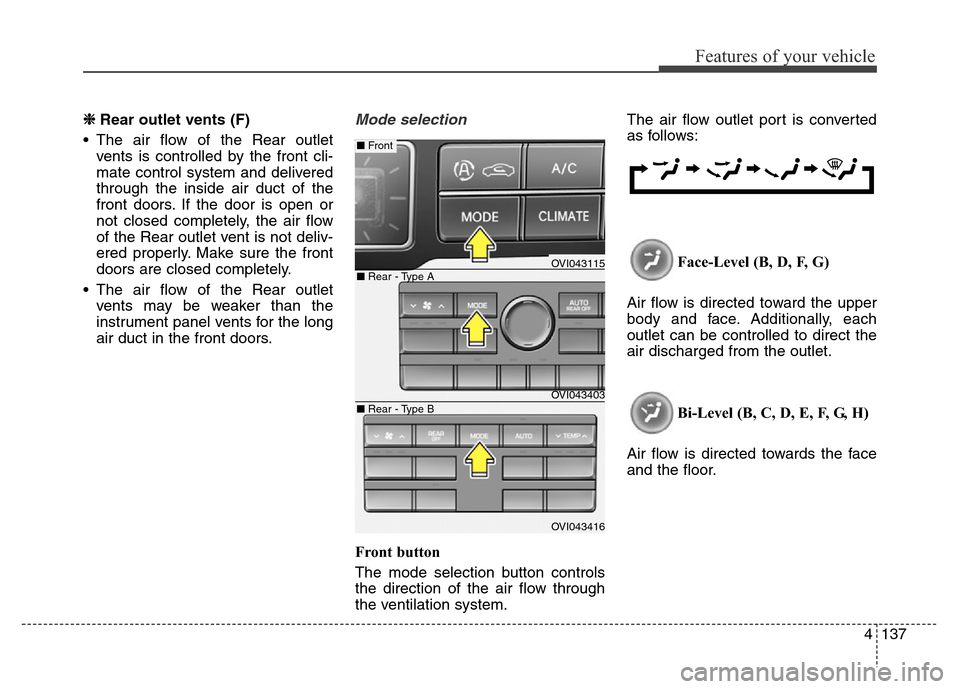
Front button
The mode selection button controls
the direction of the air flow through
the ventilation system.The air flow outlet port is converted
as follows:
Face-Level (B, D, F, G)
Air flow is directed toward the upper
body and face. Additionally, each
outlet can be controlled to direct the
air discharged from the outlet.
Bi-Level (B, C, D, E, F, G, H)
Air flow is directed towards the face
and the floor.
OVI043115
OVI043403
OVI043416
■ Rear - Type A
■ Front
■ Rear - Type B
Page 227 of 479

Features of your vehicle
138 4
Floor & Defrost (A, C, E, D, H)
Most of the air flow is directed to the
floor and the windshield with a small
amount directed to the side window
defrosters.
Floor-Level (A, C, E, D, H)
Most of the air flow is directed to the
floor, with a small amount of the air
being directed to the windshield and
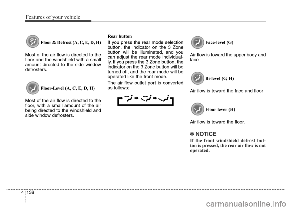
side window defrosters.Rear button
If you press the rear mode selection
button, the indicator on the 3 Zone
button will be illuminated, and you
can adjust the rear mode individual-
ly. If you press the 3 Zone button, the
indicator on the 3 Zone button will be
turned off, and the rear mode will be
operated like the front mode.
The air flow outlet port is converted
as follows:Face-level (G)
Air flow is toward the upper body and
face
Bi-level (G, H)
Air flow is toward the face and floor
Floor lever (H)
Air flow is toward the floor.
✽NOTICE
If the front windshield defrost but-
ton is pressed, the rear air flow is not
operated.
Page 239 of 479

Features of your vehicle
150 4
1. Turn the ignition switch to the ON
position.
2. Press the defroster button ( ).
3. While pressing the air conditioning
button (A/C), press the air intake
control button at least 5 times with-
in 3 seconds.
The indicator on the air intake button
blinks 3 times with 0.5 seconds of
interval. It indicates that the defog-
ging logic is canceled or returned to
the programmed status.
If the battery has been discharged or
disconnected, it resets to the defog
logic status.
Auto defogging system
Auto defogging reduces the probabil-
ity of fogging up the inside of the
windshield by automatically sensing
the moisture of inside the windshield.
The auto defogging system operates
when the heater or air conditioning is
on.This indicator illuminates
when the auto defogging
system senses the mois-
ture of inside the wind-
shield and operates.
If more moisture is in the vehicle, the
higher steps operate as follow. For
example if auto defogging does not
defog inside the windshield at step 1
Outside air position, it tries to defog
again at step 2 Blowing air toward
the windshield.
Step 1 : Outside air position
Step 2 :Operating the air conditioning
Step 3 :Blowing air toward the wind-
shield
Step 4 : Increasing air flow toward
the windshield
OVI043125
OVI049124
Page 258 of 479

Driving your vehicle
Before driving . . . . . . . . . . . . . . . . . . . . . . . . . . . . . . 5-4
• Before entering vehicle . . . . . . . . . . . . . . . . . . . . . . . . . 5-4
• Necessary inspections . . . . . . . . . . . . . . . . . . . . . . . . . 5-4
• Before starting . . . . . . . . . . . . . . . . . . . . . . . . . . . . . . . 5-4
Engine start/stop button . . . . . . . . . . . . . . . . . . . . . 5-6
• Illuminated engine start/stop button . . . . . . . . . . . . . . 5-6
• Engine start/stop button position. . . . . . . . . . . . . . . . . 5-6
Starting the engine . . . . . . . . . . . . . . . . . . . . . . . . . . 5-9
Automatic transmission (Shift by wire) . . . . . . . . 5-11
• Automatic transmission operation . . . . . . . . . . . . . . . 5-11
• Good driving practices . . . . . . . . . . . . . . . . . . . . . . . . 5-20
Brake system . . . . . . . . . . . . . . . . . . . . . . . . . . . . . 5-23
• Power brakes . . . . . . . . . . . . . . . . . . . . . . . . . . . . . . . 5-23
• Electric parking brake (EPB) . . . . . . . . . . . . . . . . . . 5-26
• Emergency braking . . . . . . . . . . . . . . . . . . . . . . . . . . . 5-29
• Auto hold . . . . . . . . . . . . . . . . . . . . . . . . . . . . . . . . . . . 5-30
• Anti-lock brake system (ABS) . . . . . . . . . . . . . . . . . . 5-34
• Electronic Stability Control (ESC) . . . . . . . . . . . . . . 5-36
• Hill-start assist control (HAC) . . . . . . . . . . . . . . . . . . 5-41
• Emergency Stop Signal (ESS) . . . . . . . . . . . . . . . . . . 5-41
• Good braking practices. . . . . . . . . . . . . . . . . . . . . . . . 5-42
Drive mode integrated control system . . . . . . . . . 5-44
• Drive mode / Snow mode . . . . . . . . . . . . . . . . . . . . . . 5-44
Electronic controlled suspension (ECS) . . . . . . . . 5-46
• To control the vehicle height . . . . . . . . . . . . . . . . . . . 5-46• ECS (electronic controlled suspension) malfunction
warning message . . . . . . . . . . . . . . . . . . . . . . . . . . . . 5-47
• Towing your vehicle. . . . . . . . . . . . . . . . . . . . . . . . . . . 5-48
Cruise control system. . . . . . . . . . . . . . . . . . . . . . . 5-50
• Cruise control speed . . . . . . . . . . . . . . . . . . . . . . . . . . 5-51
Advanced smart cruise control system. . . . . . . . . 5-55
• Smart cruise control speed . . . . . . . . . . . . . . . . . . . . . 5-56
• Smart cruise control vehicle to vehicle distance. . . . 5-60
• Distance to distance vehicle sensor . . . . . . . . . . . . . . 5-62
• To convert to cruise control mode . . . . . . . . . . . . . . . 5-63
• Limitations of the system . . . . . . . . . . . . . . . . . . . . . . 5-64
Lane departure warning system (LDWS) . . . . . . 5-70
• LDWS operation . . . . . . . . . . . . . . . . . . . . . . . . . . . . . 5-71
Intelligent accelerator pedal . . . . . . . . . . . . . . . . . 5-74
Advanced vehicle safety management (AVSM) . . 5-75
Blind spot detection system (BSD) . . . . . . . . . . . . 5-78
• Operating conditions . . . . . . . . . . . . . . . . . . . . . . . . . . 5-79
• Warning type . . . . . . . . . . . . . . . . . . . . . . . . . . . . . . . . 5-79
• Detecting sensor . . . . . . . . . . . . . . . . . . . . . . . . . . . . . . 5-80
• Warning message . . . . . . . . . . . . . . . . . . . . . . . . . . . . . 5-81
• Rear cross traffic alert . . . . . . . . . . . . . . . . . . . . . . . . 5-81
• Operating conditions . . . . . . . . . . . . . . . . . . . . . . . . . . 5-81
• Warning type . . . . . . . . . . . . . . . . . . . . . . . . . . . . . . . . 5-82
• Non-operating condition . . . . . . . . . . . . . . . . . . . . . . . 5-83
5