2014 FORD F150 service
[x] Cancel search: servicePage 287 of 472

when the low tire pressure telltale
illuminates, you should stop and check
your tires as soon as possible, and inflate
them to the proper pressure. Driving on a
significantly under-inflated tire causes the
tire to overheat and can lead to tire failure.
Under-inflation also reduces fuel efficiency
and tire tread life, and may affect the
vehicle
’s handling and stopping ability.
Please note that the TPMS is not a
substitute for proper tire maintenance, and
it is the driver ’s responsibility to maintain
correct tire pressure, even if under-inflation
has not reached the level to trigger
illumination of the TPMS low tire pressure
telltale.
Your vehicle has also been equipped with
a TPMS malfunction indicator to indicate
when the system is not operating properly.
The TPMS malfunction indicator is
combined with the low tire pressure
telltale. When the system detects a
malfunction, the telltale will flash for
approximately one minute and then remain
continuously illuminated. This sequence
will continue upon subsequent vehicle
start-ups as long as the malfunction exists.
When the malfunction indicator is
illuminated, the system may not be able
to detect or signal low tire pressure as
intended. TPMS malfunctions may occur
for a variety of reasons, including the
installation of replacement or alternate
tires or wheels on the vehicle that prevent
the TPMS from functioning properly.
Always check the TPMS malfunction
telltale after replacing one or more tires or
wheels on your vehicle to ensure that the
replacement or alternate tires and wheels
allow the TPMS to continue to function
properly. The tire pressure monitoring system
complies with part 15 of the FCC rules and
with RSS-210 of Industry Canada.
Operation is subject to the following two
conditions: (1) This device may not cause
harmful interference, and (2) This device
must accept any interference received,
including interference that may cause
undesired operation.
Changing Tires With a Tire
Pressure Monitoring System
Note:
Each road tire is equipped with a tire
pressure sensor located inside the wheel
and tire assembly cavity. The pressure
sensor is attached to the valve stem. The
pressure sensor is covered by the tire and is
not visible unless the tire is removed. Take
care when changing the tire to avoid
damaging the sensor
You should always have your tires serviced
by an authorized dealer.
Check the tire pressure periodically (at
least monthly) using an accurate tire
gauge. See Inflating Your Tires in this
chapter.
284
F150 (TF6) , enUSA Wheels and TiresE142549
Page 291 of 472

•
To reduce the chances of interference
from another vehicle, perform the
system reset procedure at least three
feet (one meter) away from another
Ford Motor Company vehicle
undergoing the system reset procedure
at the same time.
• Do not wait more than two minutes
between resetting each tire sensor or
the system will time-out and the entire
procedure will have to be repeated on
all four wheels.
• A double horn will sound indicating the
need to repeat the procedure.
Performing the System Reset Procedure
Read the entire procedure before
attempting.
1. Drive the vehicle above 20 mph (32 km/h) for at least two minutes, then
park in a safe location where you can
easily get to all four tires and have
access to an air pump.
2. Place the ignition in the off position and
keep the key in the ignition.
3. Cycle the ignition to the on position with the engine off.
4. Turn the hazard flashers on then off three times. You must accomplish this
within 10 seconds. If the reset mode
has been entered successfully, the horn
will sound once, the system indicator
will flash and a message is shown in
the information display. If this does not
occur, please try again starting at Step
2. If after repeated attempts to enter
the reset mode, the horn does not
sound, the system indicator does not
flash and no message is shown in the
information display, seek service from
your authorized dealer. 5. Train the tire pressure monitoring
system sensors in the tires using the
following system reset sequence
starting with the left front tire in the
following clockwise order: Left front
(driver's side front tire), Right front
(passenger's side front tire), Right rear
(passenger's side rear tire), Left rear
(driver's side rear tire)
6. Remove the valve cap from the valve stem on the left front tire. Decrease the
air pressure until the horn sounds.
Note: The single horn chirp confirms
that the sensor identification code has
been learned by the module for this
position. If a double horn is heard, the
reset procedure was unsuccessful, and
you must repeat it.
7. Remove the valve cap from the valve stem on the right front tire. Decrease
the air pressure until the horn sounds.
8. Remove the valve cap from the valve stem on the right rear tire. Decrease the
air pressure until the horn sounds.
9. Remove the valve cap from the valve stem on the left rear tire. Decrease the
air pressure until the horn sounds.
Training is complete after the horn
sounds for the last tire trained (driver's
side rear tire), the system indicator
stops flashing, and a message is shown
in the information display.
10. Turn the ignition off. If two short horn
beeps are heard, the reset procedure
was unsuccessful and you must
repeat it. If after repeating the
procedure and two short beeps are
heard when the ignition is turned to
off, seek assistance from your
authorized dealer.
288
F150 (TF6) , enUSA Wheels and Tires
Page 292 of 472
11.
Set all four tires to the recommended
air pressure as indicated on the
Safety Compliance Certification
Label (affixed to either the door hinge
pillar, door-latch post, or the door
edge that meets the door-latch post,
next to the driver's seating position)
or Tire Label located on the B-Pillar
or the edge of the driver's door.
CHANGING A ROAD WHEEL WARNINGS
The use of tire sealants may damage
your tire pressure monitoring system
and should not be used. However, if
you must use a sealant, the tire pressure
monitoring system sensor and valve stem
on the wheel must be replaced by an
authorized dealer. If the tire pressure monitor sensor
becomes damaged, it will no longer
function. See Tire Pressure
Monitoring System (page 283). Note:
The tire pressure monitoring system
indicator light will illuminate when the spare
tire is in use. To restore the full function of
the monitoring system, all road wheels
equipped with tire pressure monitoring
sensors must be mounted on this vehicle.
If you get a flat tire while driving, do not
apply the brake heavily. Instead, gradually
decrease your speed. Hold the steering
wheel firmly and slowly move to a safe
place on the side of the road.
Have a flat serviced by an authorized
dealer in order to prevent damage to the
system sensors
See Tire Pressure
Monitoring System (page 283). Replace
the spare tire with a road tire as soon as
possible. During repairing or replacing of
the flat tire, have the authorized dealer
inspect the system sensor for damage. Dissimilar Spare Wheel and Tire
Assembly Information WARNING
Failure to follow these guidelines
could result in an increased risk of
loss of vehicle control, injury or death.
If you have a dissimilar spare wheel and
tire, then it is intended for temporary use
only. This means that if you need to use it,
you should replace it as soon as possible
with a road wheel and tire assembly that
is the same size and type as the road tires
and wheels that were originally provided
by Ford. If the dissimilar spare tire or wheel
is damaged, it should be replaced rather
than repaired.
A dissimilar spare wheel and tire assembly
is defined as a spare wheel and tire
assembly that is different in brand, size or
appearance from the road tires and wheels
and can be one of three types:
1.
T-type mini-spare:
This spare tire
begins with the letter T for tire size and
may have Temporary Use Only molded in
the sidewall.
2. Full-size dissimilar spare with label
on wheel:
This spare tire has a label on
the wheel that states: THIS WHEEL AND
TIRE ASSEMBLY FOR TEMPORARY USE
ONLY
When driving with one of the dissimilar
spare tires listed above, do not:
• Exceed 50 mph (80 km/h)
• Load the vehicle beyond maximum
vehicle load rating listed on the Safety
Compliance Label.
• Tow a trailer.
• Use snow chains on the end of the
vehicle with the dissimilar spare tire.
• Use more than one dissimilar spare tire
at a time.
289
F150 (TF6) , enUSA Wheels and Tires
Page 293 of 472
•
Use commercial car washing
equipment.
• Try to repair the dissimilar spare tire.
Use of one of the dissimilar spare tires
listed above at any one wheel location can
lead to impairment of the following:
• Handling, stability and braking
performance.
• Comfort and noise.
• Ground clearance and parking at curbs.
• Winter weather driving capability.
• Wet weather driving capability.
• All-wheel driving capability
3. Full-size dissimilar spare without
label on wheel
When driving with the full-size dissimilar
spare wheel and tire assembly, do not:
• Exceed 70 mph (113 km/h).
• Use more than one dissimilar spare
wheel and tire assembly at a time.
• Use commercial car washing
equipment.
• Use snow chains on the end of the
vehicle with the dissimilar spare wheel
and tire assembly. The usage of a full-size dissimilar spare
wheel and tire assembly can lead to
impairment of the following:
•
Handling, stability and braking
performance.
• Comfort and noise.
• Ground clearance and parking at curbs.
• Winter weather driving capability.
• Wet weather driving capability.
• All-wheel driving capability
When driving with the full-size dissimilar
spare wheel and tire assembly additional
caution should be given to:
• Towing a trailer.
• Driving vehicles equipped with a
camper body.
• Driving vehicles with a load on the
cargo rack.
Drive cautiously when using a full-size
dissimilar spare wheel and tire assembly
and seek service as soon as possible.
Location of the Spare Tire and
Tools
The spare tire is located under the vehicle,
just forward of the rear bumper. The jack,
jack handle and lug wrench are located in
the following locations: Location
Body style
Attached to a floor bracket behind or underthe driver's seat (for easier access, move the driver seat forward)
Regular Cab
Attached to a floor bracket under the rearseat on the driver's side
SuperCab
In a plastic box in the floor under the rearseat
SuperCrew
290
F150 (TF6) , enUSA Wheels and Tires
Page 297 of 472
2. Slide the wheel partially under the
vehicle and install the retainer through
the wheel center. Pull on the cable to
align the components at the end of the
cable.
3. Turn the jack handle clockwise until the tire is raised to its stowed position
underneath the vehicle. The effort to
turn the jack handle increases
significantly and the spare tire carrier
ratchets or slips when the tire is raised
to the maximum tightness. Tighten to
the best of your ability, to the point
where the ratchet or slip occurs, if
possible. The spare tire carrier will not
allow you to overtighten. If the spare
tire carrier ratchets or slips with little
effort, take the vehicle to your
authorized dealer for assistance at your
earliest convenience. 4. Check that the tire lies flat against the
frame and is properly tightened. Try to
push or pull, then turn the tire to be
sure it will not move. Loosen and
retighten, if necessary. Failure to
properly stow the spare tire may result
in failure of the winch cable and loss
of the tire.
5. Repeat this tightness check procedure
when servicing the spare tire pressure
(every six months, as per your
scheduled maintenance information),
or at any time that the spare tire is
disturbed through service of other
components.
6. If removed, install the spare tire lock into the bumper drive tube with the
spare tire lock key and jack handle.
TECHNICAL SPECIFICATIONS
Wheel Lug Nut Torque Specifications WARNING
When a wheel is installed, always remove any corrosion, dirt or foreign materials
present on the mounting surfaces of the wheel or the surface of the wheel hub,
brake drum or brake disc that contacts the wheel. Make sure that any fasteners
that attach the rotor to the hub are secured so they do not interfere with the mounting
surfaces of the wheel. Installing wheels without correct metal-to-metal contact at the
wheel mounting surfaces can cause the wheel nuts to loosen and the wheel to come off
while your vehicle is in motion, resulting in loss of control. lb.ft (Nm)
Bolt size
148 lb.ft (200 Nm)
M14 x 2.0
* Torque specifications are for nut and bolt threads free of dirt and rust. Use only Ford
recommended replacement fasteners.
294
F150 (TF6) , enUSA Wheels and Tires
Page 308 of 472
1
Ford recommends using Motorcraft (Ford) DOT 4 LV High Performance Motor Vehicle
Brake Fluid or equivalent meeting WSS-M6C65-A2. Use of any fluid other than the
recommended fluid may cause degraded brake performance and not meet the Ford
performance standards. Keep brake fluid clean and dry. Contamination with dirt, water,
petroleum products or other materials may result in brake system damage and possible
failure.
2 The design of your engine allows for the use of Motorcraft engine oils or equivalent oils
that meet Ford specifications. It is also acceptable to use an engine oil of recommended
viscosity grade that meets API SN requirements and displays the API certification mark
for gasoline engines.
3 Do not use supplemental engine oil additives in your engine. They are unnecessary and
could lead to engine damage not covered by your Ford warranty.
Do not use API S category oils labeled as SN, SM, SL or lower category unless the label
also displays the API certification mark. These oils do not meet the requirements of the
engine and emission system.
4 Add the coolant type originally equipped in your vehicle.
5 Service refill capacity is determined by filling the axle to 1/4-9/16 inch (6-14 millimeter)
below the bottom of the filler hole with the vehicle on a level surface. Add 4 fl oz. (118
milliliters) of Additive Friction Modifier XL-3 (US) / CXL-3 (Canada) or equivalent meeting
Ford specification EST-M2C118-A, for complete fill of 8.8-inch Traction-Lok axles.
6 Filled with a synthetic rear axle lubricant, consider the rear axle on your vehicle filled for
life. You do not need to check or change the rear axle lubricant unless you suspect a leak.
Change the rear axle lubricant any time you have submerged the rear axle in water.
7 Service refill capacity is determined by filling the transfer case to the bottom of the filler
hole with the vehicle on a level surface.
8 Make sure the correct automatic transmission fluid is used. Transmission fluid
requirements are indicated on the dipstick blade or the dipstick handle. Before adding,
check the container to verify the fluid is of the correct type. Refer to your scheduled
maintenance information to determine the correct service interval.
Note: Automatic transmissions that require MERCON LV should only use MERCON LV fluid.
Use of any fluid other than the recommended fluid may cause transmission damage.
9 Indicates only approximate dry-fill capacity. Some applications may vary based on cooler
size and if equipped with an in-tank cooler. Use the indication on the dipstick, showing
the normal operating range, to determine the amount of transmission fluid and the fluid
level.
10 See the Warning below: WARNING
The air conditioning refrigerant system contains refrigerant R-134a under high
pressure. Opening the air conditioning refrigerant system can cause personal injury.
Have the air conditioning refrigerant system serviced only by qualified personnel.
305
F150 (TF6) , enUSA Capacities and Specifications
Page 321 of 472
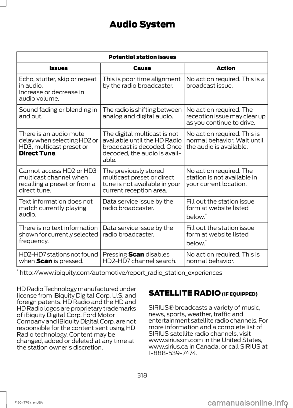
Potential station issues
Action
Cause
Issues
No action required. This is a
broadcast issue.
This is poor time alignment
by the radio broadcaster.
Echo, stutter, skip or repeat
in audio.
Increase or decrease in
audio volume.
No action required. The
reception issue may clear up
as you continue to drive.
The radio is shifting between
analog and digital audio.
Sound fading or blending in
and out.
No action required. This is
normal behavior. Wait until
the audio is available.
The digital multicast is not
available until the HD Radio
broadcast is decoded. Once
decoded, the audio is avail-
able.
There is an audio mute
delay when selecting HD2 or
HD3, multicast preset or
Direct Tune.
No action required. The
station is not available in
your current location.
The previously stored
multicast preset or direct
tune is not available in your
current reception area.
Cannot access HD2 or HD3
multicast channel when
recalling a preset or from a
direct tune.
Fill out the station issue
form at website listed
below.*
Data service issue by the
radio broadcaster.
Text information does not
match currently playing
audio.
Fill out the station issue
form at website listed
below.*
Data service issue by the
radio broadcaster.
There is no text information
shown for currently selected
frequency.
No action required. This is
normal behavior.
Pressing
Scan disables
HD2-HD7 channel search.
HD2-HD7 stations not found
when Scan is pressed.
* http://www.ibiquity.com/automotive/report_radio_station_experiences
HD Radio Technology manufactured under
license from iBiquity Digital Corp. U.S. and
foreign patents. HD Radio and the HD and
HD Radio logos are proprietary trademarks
of iBiquity Digital Corp. Ford Motor
Company and iBiquity Digital Corp. are not
responsible for the content sent using HD
Radio technology. Content may be
changed, added or deleted at any time at
the station owner's discretion. SATELLITE RADIO
(IF EQUIPPED)
SIRIUS® broadcasts a variety of music,
news, sports, weather, traffic and
entertainment satellite radio channels. For
more information and a complete list of
SIRIUS satellite radio channels, visit
www.siriusxm.com in the United States,
www.sirius.ca in Canada, or call SIRIUS at
1-888-539-7474.
318
F150 (TF6) , enUSA Audio System
Page 322 of 472
Note:
This receiver includes the eCos
real-time operating system. eCos is
published under the eCos License.
Satellite Radio Reception Factors Potential satellite radio reception issues
For optimal reception performance, keep the antenna
clear of snow and ice build-up and keep luggage and other
material as far away from the antenna as possible.
Antenna obstructions
Hills, mountains, tall buildings, bridges, tunnels, freeway
overpasses, parking garages, dense tree foliage and
thunderstorms can interfere with your reception.
Terrain
When you pass a ground-based broadcast-repeating
tower, a stronger signal may overtake a weaker one and
the audio system may mute.
Station overload
Your display may show ACQUIRING . . . to indicate the
interference and the audio system may mute.
Satellite radio signal interfer-
ence
SIRIUS® Satellite Radio Service
Note: SIRIUS reserves the unrestricted right
to change, rearrange, add or delete
programming including canceling, moving
or adding particular channels, and its prices,
at any time, with or without notice to you.
Ford Motor Company shall not be
responsible for any such programming
changes. SIRIUS satellite radio is a
subscription-based satellite radio service
that broadcasts a variety of music, sports,
news, weather, traffic and entertainment
programming. Your factory-installed
SIRIUS satellite radio system includes
hardware and a limited subscription term,
which begins on the date of sale or lease
of your vehicle. See an authorized dealer
for availability.
For more information on extended
subscription terms (a service fee is
required), the online media player and a
complete list of SIRIUS satellite radio
channels, and other features, please visit
www.siriusxm.com in the United States,
www.sirius.ca in Canada, or call SIRIUS at
1-888-539-7474.
319
F150 (TF6) , enUSA Audio SystemE142593