2014 FORD EXPEDITION turn signal
[x] Cancel search: turn signalPage 106 of 519

4X4
Illuminates when four-wheel drive high is engaged. If the light fails
to display when the ignition is turned on, or remains on, have the
system serviced immediately by your authorized dealer.
4X4 LOW
Illuminates when four-wheel drive low is engaged. If the light fails
to display when the ignition is turned on, or remains on, have the
system serviced immediately by your authorized dealer.
4X4 AUTO
Displays when using the 4x4 system.
AUDIBLE WARNINGS AND INDICATORS
Key In Ignition Warning Chime
Sounds when the key is left in the ignition in the off or accessory
position and the driver’s door is opened.
Headlamps On Warning Chime
Sounds when the headlamps or parking lamps are on, the ignition is off
(the key is not in the ignition) and the driver’s door is opened.
Parking Brake On Warning Chime
Sounds when you have left the parking brake on and drive your vehicle.
If the warning chime remains on after you have released the parking
brake, have the system checked by your authorized dealer immediately.
Turn Signal Chime
Sounds when the direction indicator has been activated to signal a turn
and not turned off after the vehicle is driven more than 1.5 miles
(2.4 km).
Instrument Cluster105
2014 Expedition(exd)
Owners Guide gf, 1st Printing, June 2013
USA(fus)
Page 160 of 519
Note:We recommend that upon the sale or lease termination of your
vehicle, you erase the programmed function buttons for security reasons.
SeeErasing the function button codeslater in this section.
Note:You can program a maximum of three devices. To change or
replace any of the three devices after it has been initially programmed,
you must first erase the current settings. SeeErasing the function
button codeslater in this section.
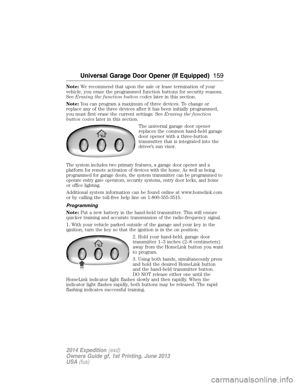
The universal garage door opener
replaces the common hand-held garage
door opener with a three-button
transmitter that is integrated into the
driver’s sun visor.
The system includes two primary features, a garage door opener and a
platform for remote activation of devices with the home. As well as being
programmed for garage doors, the system transmitter can be programmed to
operate entry gate operators, security systems, entry door locks, and home
or office lighting.
Additional system information can be found online at www.homelink.com
or by calling the toll-free help line on 1-800-355-3515.
Programming
Note:Put a new battery in the hand-held transmitter. This will ensure
quicker training and accurate transmission of the radio-frequency signal.
1. With your vehicle parked outside of the garage and your key in the
ignition, turn the key so that the ignition is in the on position.
2. Hold your hand-held, garage door
transmitter 1–3 inches (2–8 centimeters)
away from the HomeLink button you want
to program.
3. Using both hands, simultaneously press
and hold the desired HomeLink button
and the hand-held transmitter button.
DO NOT release either one until the
HomeLink indicator light flashes slowly and then rapidly. When the
indicator light flashes rapidly, both buttons may be released. The rapid
flashing indicates successful training.
Universal Garage Door Opener (If Equipped)159
2014 Expedition(exd)
Owners Guide gf, 1st Printing, June 2013
USA(fus)
Page 161 of 519
4. Press and hold the HomeLink button you programmed for five
seconds, then release. You may need to do this twice to activate the
door. If your garage door does not operate, watch the HomeLink
indicator light.
If the indicator light stays on, the programming is complete. Press and
release the programmed HomeLink button, and then begin programming
your garage door opener. See below for Steps5–7.
If the indicator light flashes rapidly for two seconds and then turns to a
constant light, the HomeLink button is not programmed yet. Do the
following:
Press and hold the HomeLink button while you press and release the
hand-held transmitter button every two seconds. The HomeLink
indicator light will flash slowly and then rapidly once the HomeLink
function button recognizes and accepts the hand-held transmitter’s radio
frequency signal.
After programming the HomeLink button, follow Steps5–7aslisted
below to program your garage door opener.
Note:You may need a ladder to reach the unit
and you may need to remove the cover or
lamp lens on your garage door opener.
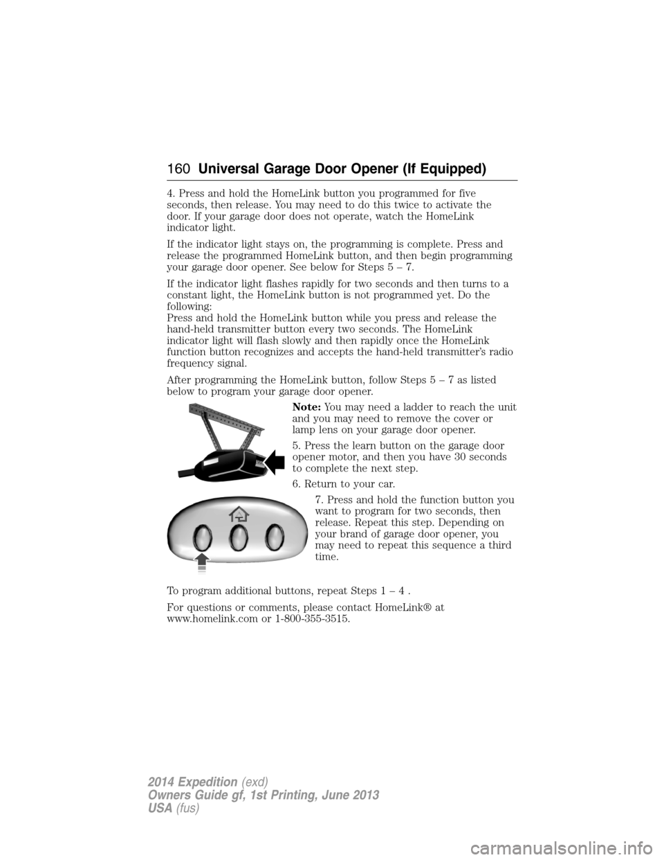
5. Press the learn button on the garage door
opener motor, and then you have 30 seconds
to complete the next step.
6. Return to your car.
7. Press and hold the function button you
want to program for two seconds, then
release. Repeat this step. Depending on
your brand of garage door opener, you
may need to repeat this sequence a third
time.
To program additional buttons, repeat Steps1–4.
For questions or comments, please contact HomeLink® at
www.homelink.com or 1-800-355-3515.
160Universal Garage Door Opener (If Equipped)
2014 Expedition(exd)
Owners Guide gf, 1st Printing, June 2013
USA(fus)
Page 231 of 519
Trailer Towing Connector (Vehicles with a Trailer Towing Package
and 7–Pin Connector)
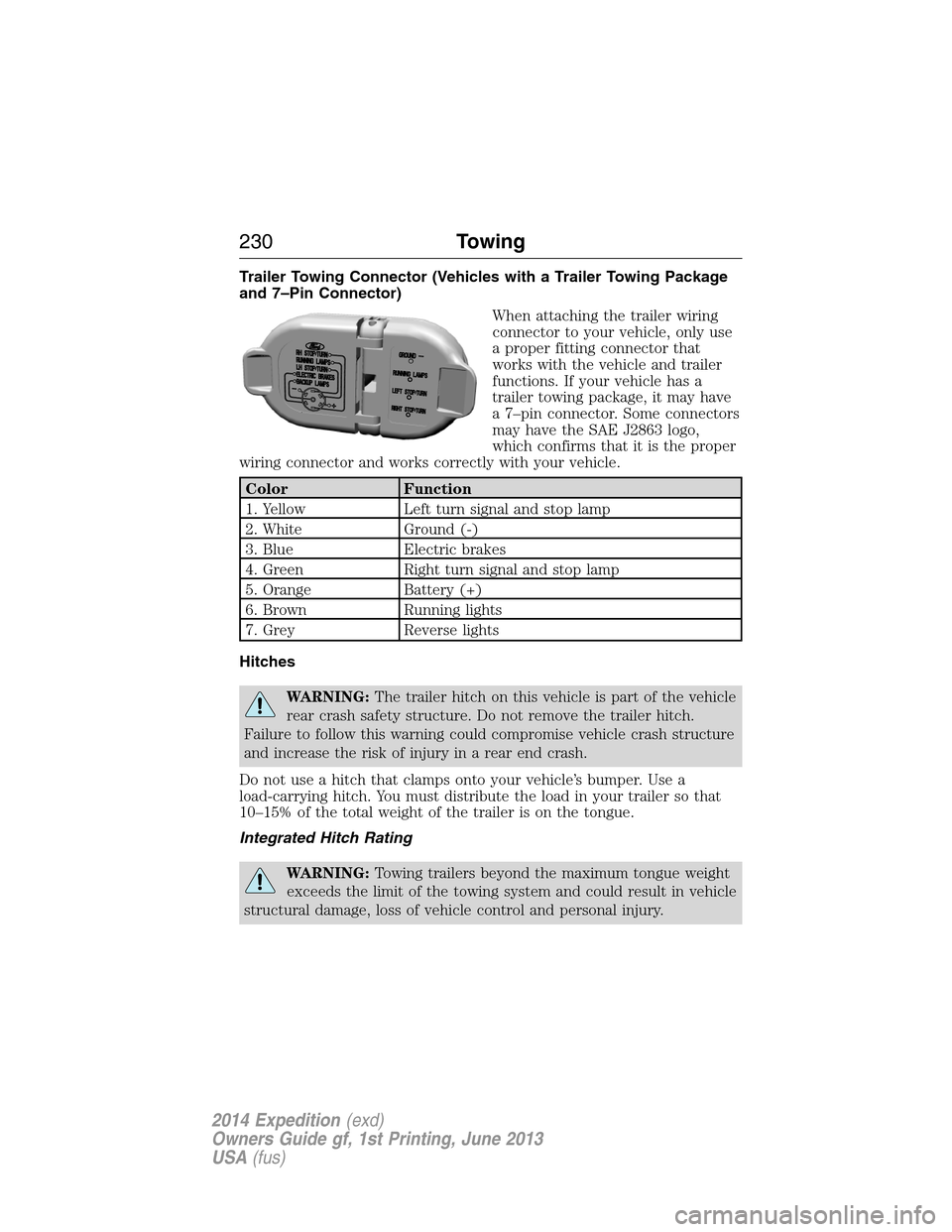
When attaching the trailer wiring
connector to your vehicle, only use
a proper fitting connector that
works with the vehicle and trailer
functions. If your vehicle has a
trailer towing package, it may have
a 7–pin connector. Some connectors
may have the SAE J2863 logo,
which confirms that it is the proper
wiring connector and works correctly with your vehicle.
Color Function
1. Yellow Left turn signal and stop lamp
2. White Ground (-)
3. Blue Electric brakes
4. Green Right turn signal and stop lamp
5. Orange Battery (+)
6. Brown Running lights
7. Grey Reverse lights
Hitches
WARNING:The trailer hitch on this vehicle is part of the vehicle
rear crash safety structure. Do not remove the trailer hitch.
Failure to follow this warning could compromise vehicle crash structure
and increase the risk of injury in a rear end crash.
Do not use a hitch that clamps onto your vehicle’s bumper. Use a
load-carrying hitch. You must distribute the load in your trailer so that
10–15% of the total weight of the trailer is on the tongue.
Integrated Hitch Rating
WARNING:Towing trailers beyond the maximum tongue weight
exceeds the limit of the towing system and could result in vehicle
structural damage, loss of vehicle control and personal injury.
230Towing
2014 Expedition(exd)
Owners Guide gf, 1st Printing, June 2013
USA(fus)
Page 239 of 519
Trailer Lamps
WARNING:Never connect any trailer lamp wiring to the
vehicle’s tail lamp wiring; this may damage the electrical system
resulting in a fire. Contact an authorized dealer as soon as possible for
assistance in proper trailer tow wiring installation. Additional electrical
equipment may be required.
Trailer lamps are required on most towed vehicles. Make sure all running
lights, brake lights, turn signals and hazard lights are working.
Before Towing a Trailer
Practice turning, stopping and backing up to get the feel of your
vehicle-trailer combination before starting on a trip. When turning, make
wider turns so the trailer wheels clear curbs and other obstacles.
When Towing a Trailer
•Do not drive faster than 70 mph (113 km/h) during the first 500 miles
(800 kilometers).
•Do not make full-throttle starts.
•Check your hitch, electrical connections and trailer wheel lug nuts
thoroughly after you have traveled 50 miles (80 kilometers).
•When stopped in congested or heavy traffic during hot weather, place
the gearshift in positionPto aid engine and transmission cooling and
to help A/C performance.
•Turn off the speed control with heavy loads or in hilly terrain. The
speed control may turn off automatically when you are towing on
long, steep grades.
•Shift to a lower gear when driving down a long or steep hill. Do not
apply the brakes continuously, as they may overheat and become less
effective.
•If your transmission is equipped with a Grade Assist or Tow/Haul
feature, use this feature when towing. This provides engine braking
and helps eliminate excessive transmission shifting for optimum fuel
economy and transmission cooling.
•If your vehicle is equipped with AdvanceTrac™ with RSC, this system
may turn on during typical cornering maneuvers with a heavily loaded
trailer. This is normal. Turning the corner at a slower speed while
towing may reduce this tendency.
238Towing
2014 Expedition(exd)
Owners Guide gf, 1st Printing, June 2013
USA(fus)
Page 248 of 519
Vehicles Sold in the U.S.: Using Roadside Assistance
Complete the roadside assistance identification card and place it in your
wallet for quick reference. This card is found in the owner’s manual
portfolio in the glove compartment.
U.S. Ford vehicle customers who require Roadside Assistance, call
1-800-241-3673.
If you need to arrange roadside assistance for yourself, Ford Motor
Company will reimburse a reasonable amount for towing to the nearest
dealership within 35 miles (56 kilometers). To obtain reimbursement
information, U.S. Ford vehicle customers call 1-800-241-3673. Customers
will be asked to submit their original receipts.
Vehicles Sold in Canada: Getting Roadside Assistance
Canadian customers who require roadside assistance, call
1–800–665–2006.
Vehicles Sold in Canada: Using Roadside Assistance
For your convenience, you may complete the roadside assistance
identification card found in the centerfold of this warranty guide and
retain for future reference.
Canadian roadside coverage and benefits may differ from the U.S.
coverage. If you require more information, please refer to the coverage
section of your warranty guide, call us in Canada at 1-800-665-2006, or
visit our website at www.ford.ca.
HAZARD WARNING FLASHERS
The hazard flasher control is located on the instrument panel
by the radio. Use it when your vehicle is disabled and is
creating a safety hazard for other motorists.
•Press the flasher control and all front and rear direction signals will
flash.
•Press the flasher control again to turn them off.
Note:With extended use, the flashers may run down your 12–volt
battery.
Roadside Emergencies247
2014 Expedition(exd)
Owners Guide gf, 1st Printing, June 2013
USA(fus)
Page 267 of 519
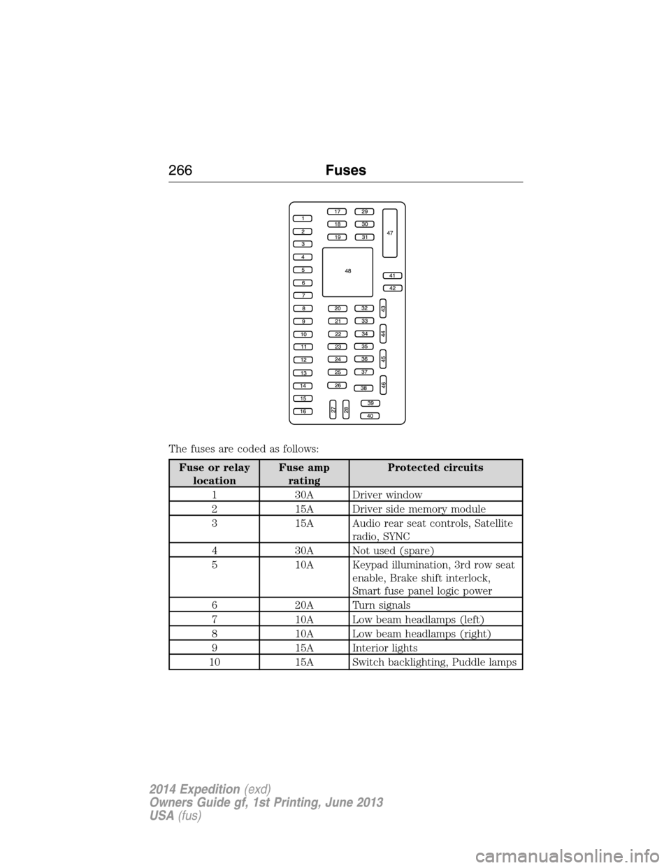
The fuses are coded as follows:
Fuse or relay
locationFuse amp
ratingProtected circuits
1 30A Driver window
2 15A Driver side memory module
3 15A Audio rear seat controls, Satellite
radio, SYNC
4 30A Not used (spare)
5 10A Keypad illumination, 3rd row seat
enable, Brake shift interlock,
Smart fuse panel logic power
6 20A Turn signals
7 10A Low beam headlamps (left)
8 10A Low beam headlamps (right)
9 15A Interior lights
10 15A Switch backlighting, Puddle lamps
266Fuses
2014 Expedition(exd)
Owners Guide gf, 1st Printing, June 2013
USA(fus)
Page 290 of 519
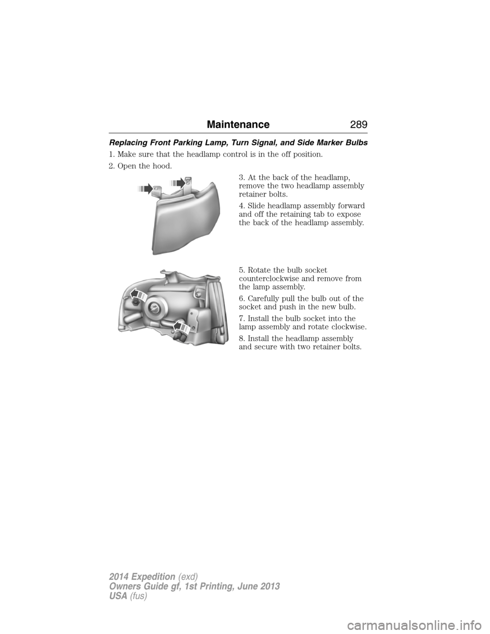
Replacing Front Parking Lamp, Turn Signal, and Side Marker Bulbs
1. Make sure that the headlamp control is in the off position.
2. Open the hood.
3. At the back of the headlamp,
remove the two headlamp assembly
retainer bolts.
4. Slide headlamp assembly forward
and off the retaining tab to expose
the back of the headlamp assembly.
5. Rotate the bulb socket
counterclockwise and remove from
the lamp assembly.
6. Carefully pull the bulb out of the
socket and push in the new bulb.
7. Install the bulb socket into the
lamp assembly and rotate clockwise.
8. Install the headlamp assembly
and secure with two retainer bolts.
Maintenance289
2014 Expedition(exd)
Owners Guide gf, 1st Printing, June 2013
USA(fus)