2014 FORD EXPEDITION height
[x] Cancel search: heightPage 215 of 519
AUTO LEVELING SUSPENSION SYSTEM (if equipped)
The automatic leveling suspension system is designed to improve ride,
handling and general vehicle performance during:
•Certain road conditions
•Steering maneuvers
•Braking
•Acceleration
•Towing
This system keeps the rear of your vehicle at a constant level through a
hydraulic pump inside each rear shock. Depending on the payload or
road surface conditions it will take approximately 2 miles (3.2 km) for
the leveling to complete.
If the loaded vehicle is not moved for approximately 12 hours, the
leveling system may bleed down to a lower height. This can be especially
apparent if a trailer is left attached to the parked vehicle for long periods
of time. You must drive your vehicle in order to re-level the suspension.
If a self-equalizing hitch is being used, your vehicle should be drive
approximately 2 miles (3.2 km) with the trailer prior to adjusting
(leveling) the hitch.
214Driving Aids
2014 Expedition(exd)
Owners Guide gf, 1st Printing, June 2013
USA(fus)
Page 232 of 519
The standard integrated hitch has two ratings depending on mode of
operation:
•Weight-carrying mode requires a draw bar and hitch ball. The draw
bar supports all the vertical tongue load of the trailer.
•Weight-distributing mode requires an aftermarket weight-distributing
system, which includes draw bar, hitch ball, spring bars and snap-up
brackets. This system distributes the vertical tongue load of the trailer
between the truck and the trailer.
Mode Maximum trailer
weight - lb. (kg)Maximum tongue
weight - lb. (kg)
Weight-carrying 6000 (2721) 600 (272)
Weight-distributing 9200 (4173) 920 (417)
Note:These are hitch ratings only. Actual vehicle ratings are dependent
on engine, transmission and axle combinations.
Weight-distributing Hitch – Vehicles without Automatic Leveling
Suspension
WARNING:Do not adjust a weight-distributing hitch to any
position where the rear bumper of the vehicle is higher than it
was before attaching the trailer. Doing so will defeat the function of the
weight-distributing hitch, which may cause unpredictable handling, and
could result in serious personal injury.
When hooking-up a trailer using a weight-distributing hitch, always use
the following procedure:
1. Park your vehicle, without the trailer, on a level surface.
2. Measure the height of the top of your vehicle’s front wheel opening
on the fender. This is H1.
3. Attach the trailer to your vehicle without the weight-distributing bars
connected.
4. Measure the height of the top of your vehicle’s front wheel opening
on the fender a second time. This is H2.
5. Install and adjust the tension in the weight distributing bars so that
the height of the front fender is approximately halfway between H1
and H2.
6. Check that the trailer is level or slightly nose down toward your
vehicle. If not, adjust the ball height accordingly and repeat
Steps 2–6.
Towing231
2014 Expedition(exd)
Owners Guide gf, 1st Printing, June 2013
USA(fus)
Page 233 of 519
Once the trailer is level or slightly nose down toward the vehicle:
•Lock the bar tension adjuster in place.
•Check that the trailer tongue securely attaches and locks onto the
hitch.
•Install safety chains, lighting, and trailer brake controls as required by
law or the trailer manufacturer.
Weight-distributing Hitch – Vehicles with Automatic Leveling
Suspension
WARNING:Do not adjust a weight-distributing hitch to any
position where the rear bumper of the vehicle is higher than it
was before attaching the trailer. Doing so will defeat the function of the
weight-distributing hitch, which may cause unpredictable handling, and
could result in serious personal injury.
Note:If you do not move the loaded vehicle for approximately 12 hours,
the leveling system may bleed down to a lower height. This can be
especially apparent if you leave a trailer attached to the parked vehicle
for long periods. You must drive your vehicle in order to re-level the
suspension.
When connecting a trailer to a vehicle with automatic leveling suspension
using a weight-distributing hitch, always use the following procedure:
1. Load the interior of the vehicle to a weight similar to that which you
intend to carry when towing. This includes things such as passenger
weight and cargo.
2. Drive the vehicle for approximately 2 miles (3 kilometers) to re-level
the suspension.
3. Park your vehicle, without the trailer, on a level surface.
4. Measure the height to the top of your vehicle’s front wheel opening
on the fender. This is H1.
5. Attach the trailer to your vehicle without the weight-distributing bars
connected.
6. Make sure you securely attach and lock the trailer tongue to the
hitch.
7. Install safety chains, lighting, and trailer brake controls as required
by law or the trailer manufacturer.
8. Drive the vehicle and trailer at 20–25 mph (32–40 km/h) for
approximately 2 miles (3 kilometers) to re-level the suspension.
9. Park your vehicle and trailer on a level surface.
10. Measure the height to the top of your vehicles front wheel opening
on the fender a second time. This is H2.
232Towing
2014 Expedition(exd)
Owners Guide gf, 1st Printing, June 2013
USA(fus)
Page 234 of 519
11. Install and adjust the tension in the weight distributing bars so that
the height of the front fender is approximately halfway between H1
and H2.
12. Check that the trailer is level or slightly nose down toward the
vehicle. If it is not, remove the trailer, adjust the ball height
accordingly, and repeat Steps 5 -11.
Once the trailer is level or slightly nose down toward the vehicle:
•Lock the bar tension adjuster in place.
•Check that the trailer tongue securely attaches and locks onto the
hitch.
•Install safety chains, lighting, and trailer brake controls as required by
law or the trailer manufacturer.
Safety Chains
Note:Do not attach safety chains to the bumper.
Always connect the trailer’s safety chains to the frame or hook retainers
of your vehicle hitch.
To connect the trailer’s safety chains, cross the chains under the trailer
tongue and allow enough slack for turning tight corners. Do not allow the
chains to drag on the ground.
Trailer Brakes
WARNING:Do not connect a trailer’s hydraulic brake system
directly to your vehicle’s brake system. Your vehicle may not have
enough braking power and your chances of having a collision greatly
increase.
Electric brakes and manual, automatic or surge-type trailer brakes are
safe if you install them properly and adjust them to the manufacturer’s
specifications. The trailer brakes must meet local and federal regulations.
The rating for the tow vehicle’s braking system operation is at
the gross vehicle weight rating, not the gross combined weight
rating.
Separate functioning brake systems are required for safe control
of towed vehicles and trailers weighing more than 1500 pounds
(680 kilograms) when loaded.
Towing233
2014 Expedition(exd)
Owners Guide gf, 1st Printing, June 2013
USA(fus)
Page 287 of 519
ADJUSTING THE HEADLAMPS
The headlamps on your vehicle are properly aimed at the assembly plant.
If your vehicle has been in an accident, an authorized dealer should
check the alignment of your headlamps.
Vertical Aim Adjustment
1. Park the vehicle directly in front of a wall or screen on a level surface,
approximately 25 feet (7.6 meters)
away.
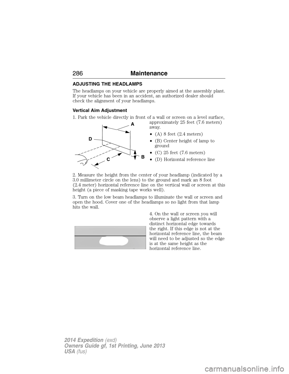
•(A) 8 feet (2.4 meters)
•(B) Center height of lamp to
ground
•(C) 25 feet (7.6 meters)
•(D) Horizontal reference line
2. Measure the height from the center of your headlamp (indicated by a
3.0 millimeter circle on the lens) to the ground and mark an 8 foot
(2.4 meter) horizontal reference line on the vertical wall or screen at this
height (a piece of masking tape works well).
3. Turn on the low beam headlamps to illuminate the wall or screen and
open the hood. Cover one of the headlamps so no light from that lamp
hits the wall.
4. On the wall or screen you will
observe a light pattern with a
distinct horizontal edge towards
the right. If this edge is not at the
horizontal reference line, the beam
will need to be adjusted so the edge
is at the same height as the
horizontal reference line.
C
A
B
D
286Maintenance
2014 Expedition(exd)
Owners Guide gf, 1st Printing, June 2013
USA(fus)
Page 310 of 519
INFORMATION CONTAINED ON THE TIRE SIDEWALL
Both U.S. and Canada Federal regulations require tire manufacturers to
place standardized information on the sidewall of all tires. This information
identifies and describes the fundamental characteristics of the tire and also
provides a U.S. DOT Tire Identification Number for safety standard
certification and in case of a recall.
Information on P Type Tires
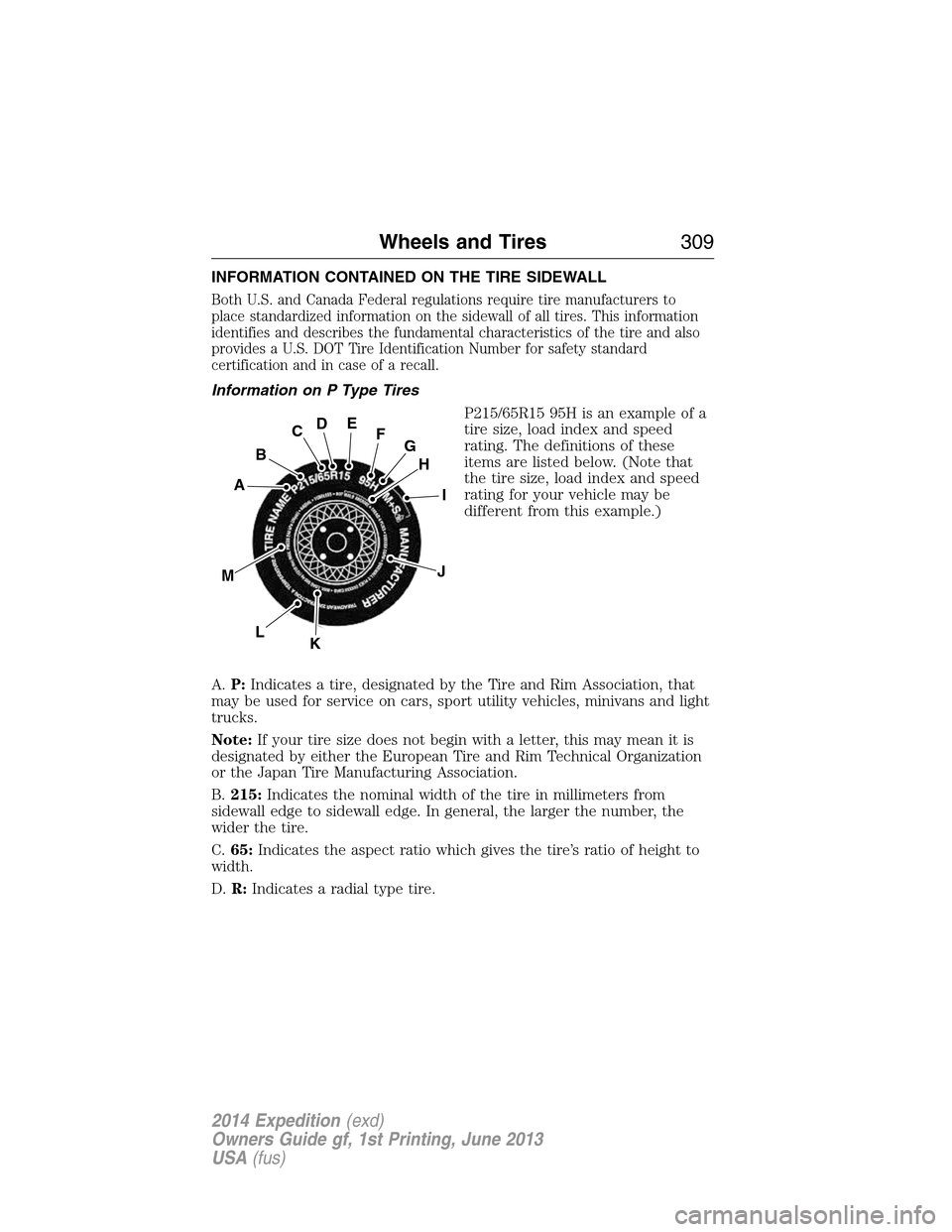
P215/65R15 95H is an example of a
tire size, load index and speed
rating. The definitions of these
items are listed below. (Note that
the tire size, load index and speed
rating for your vehicle may be
different from this example.)
A.P:Indicates a tire, designated by the Tire and Rim Association, that
may be used for service on cars, sport utility vehicles, minivans and light
trucks.
Note:If your tire size does not begin with a letter, this may mean it is
designated by either the European Tire and Rim Technical Organization
or the Japan Tire Manufacturing Association.
B.215:Indicates the nominal width of the tire in millimeters from
sidewall edge to sidewall edge. In general, the larger the number, the
wider the tire.
C.65:Indicates the aspect ratio which gives the tire’s ratio of height to
width.
D.R:Indicates a radial type tire.
H
I
J
KL
M
A
B
CDEFG
Wheels and Tires309
2014 Expedition(exd)
Owners Guide gf, 1st Printing, June 2013
USA(fus)
Page 314 of 519
Information on T Type Tires
T type tires have some additional
information beyond those of P type
tires. These differences are
described below.
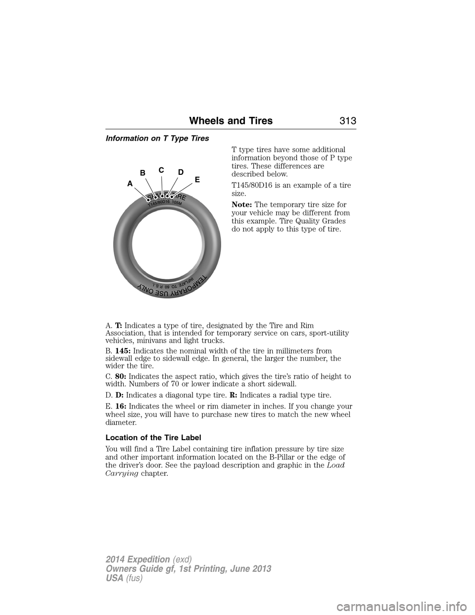
T145/80D16 is an example of a tire
size.
Note:The temporary tire size for
your vehicle may be different from
this example. Tire Quality Grades
do not apply to this type of tire.
A.T:Indicates a type of tire, designated by the Tire and Rim
Association, that is intended for temporary service on cars, sport-utility
vehicles, minivans and light trucks.
B.145:Indicates the nominal width of the tire in millimeters from
sidewall edge to sidewall edge. In general, the larger the number, the
wider the tire.
C.80:Indicates the aspect ratio, which gives the tire’s ratio of height to
width. Numbers of 70 or lower indicate a short sidewall.
D.D:Indicates a diagonal type tire.R:Indicates a radial type tire.
E.16:Indicates the wheel or rim diameter in inches. If you change your
wheel size, you will have to purchase new tires to match the new wheel
diameter.
Location of the Tire Label
You will find a Tire Label containing tire inflation pressure by tire size
and other important information located on the B-Pillar or the edge of
the driver’s door. See the payload description and graphic in theLoad
Carryingchapter.
A
BCDE
Wheels and Tires313
2014 Expedition(exd)
Owners Guide gf, 1st Printing, June 2013
USA(fus)
Page 317 of 519
(4.15 bar). For full-size and dissimilar spare tires, seeDissimilar Spare
Tire and Wheel Assembly InformationunderChanging a Road Wheel
in this chapter. Store and maintain at the higher of the front and rear
inflation pressure as shown on the Tire Label.
6. Visually inspect the tires to make sure there are no nails or other
objects embedded that could poke a hole in the tire and cause an air
leak.
7. Check the sidewalls to make sure there are no gouges, cuts or bulges.
Inspecting Your Tires and Wheel Valve Stems
Periodically inspect the tire treads for uneven or excessive wear and
remove objects such as stones, nails or glass that may be wedged in the
tread grooves. Check the tire and valve stems for holes, cracks, or cuts
that may permit air leakage and repair or replace the tire and replace
the valve stem. Inspect the tire sidewalls for cracking, cuts, bruises and
other signs of damage or excessive wear. If internal damage to the tire is
suspected, have the tire demounted and inspected in case it needs to be
repaired or replaced. For your safety, tires that are damaged or show
signs of excessive wear should not be used because they are more likely
to blow out or fail.
Improper or inadequate vehicle maintenance can cause tires to wear
abnormally. Inspect all your tires, including the spare, frequently, and
replace them if one or more of the following conditions exist:
Tire Wear
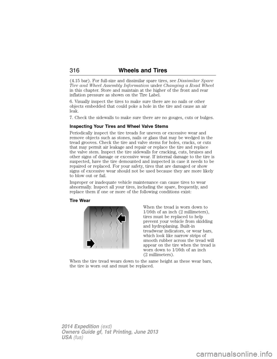
When the tread is worn down to
1/16th of an inch (2 millimeters),
tires must be replaced to help
prevent your vehicle from skidding
and hydroplaning. Built-in
treadwear indicators, or wear bars,
which look like narrow strips of
smooth rubber across the tread will
appear on the tire when the tread is
worn down to 1/16th of an inch
(2 millimeters).
When the tire tread wears down to the same height as these wear bars,
the tire is worn out and must be replaced.
316Wheels and Tires
2014 Expedition(exd)
Owners Guide gf, 1st Printing, June 2013
USA(fus)