Page 253 of 476

CAUTION!(Continued)
above or below the sensors will not be detected
when they are in close proximity.
• The vehicle must be driven slowly when using
ParkSense in order to be able to stop in time
when an obstacle is detected. It is recommended
that the driver looks over his/her shoulder when
using ParkSense.
If it’s necessary to keep the trailer hitch and hitch ball
assembly mounted for a long period, it is possible to
filter out the trailer hitch and hitch ball assembly
presence in sensor field of view. The filtering operation
must be performed only by an authorized dealer.
LANESENSE — IF EQUIPPED
LaneSense Operation
The LaneSense system is operational at speeds above
37 mph (60 km/h) and below 112 mph (180 km/h). The
LaneSense system uses a forward looking camera to
detect lane markings and measure vehicle position
within the lane boundaries. When both lane markings are detected and the driver
unintentionally drifts out of the lane (no turn signal
applied), the LaneSense system provides a haptic warn-
ing in the form of torque applied to the steering wheel
to prompt the driver to remain within the lane bound-
aries. If the driver continues to unintentionally drift out
of the lane, the LaneSense system provides a visual
warning through the instrument cluster display to
prompt the driver to remain within the lane boundaries.
The driver may manually override the haptic warning
by applying torque into the steering wheel at any time.
When only a single lane marking is detected and the
driver unintentionally drifts across the lane marking
(no turn signal applied), the LaneSense system provides
a visual warning through the instrument cluster display
to prompt the driver to remain within the lane. When
only a single lane marking is detected, a haptic (torque)
warning will not be provided.
NOTE:
When operating conditions have been met, the
LaneSense system will monitor if the driver ’s hands are
on the steering wheel and provides an audible warning
to the driver when the driver ’s hands are not detected
on the steering wheel. The system will cancel if the
driver does not return their hands to the wheel.
7
STARTING AND OPERATING 251
Page 255 of 476

NOTE:The LaneSense system operates with the similar
behavior for a right lane departure when only the right
lane marking has been detected.
Left Lane Departure — Both Lanes Detected
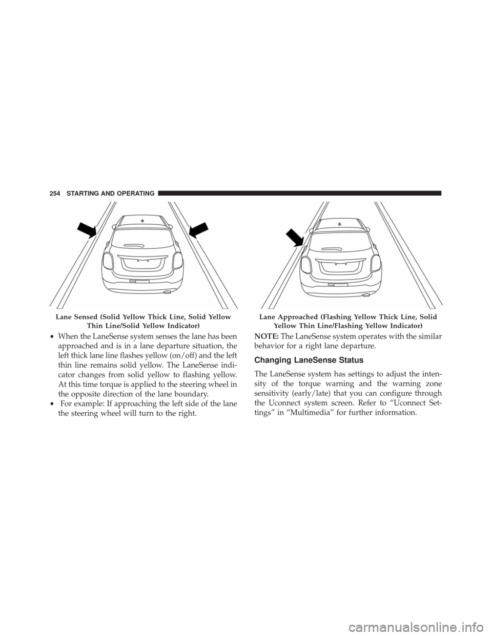
• When the LaneSense system is on, the lane lines turn
from gray to white to indicate that both of the lane
markings have been detected. The LaneSense indica-
tor is solid green when both lane markings have been
detected and the system is “armed” to provide visual warnings in the instrument cluster display and a
torque warning in the steering wheel if an uninten-
tional lane departure occurs.
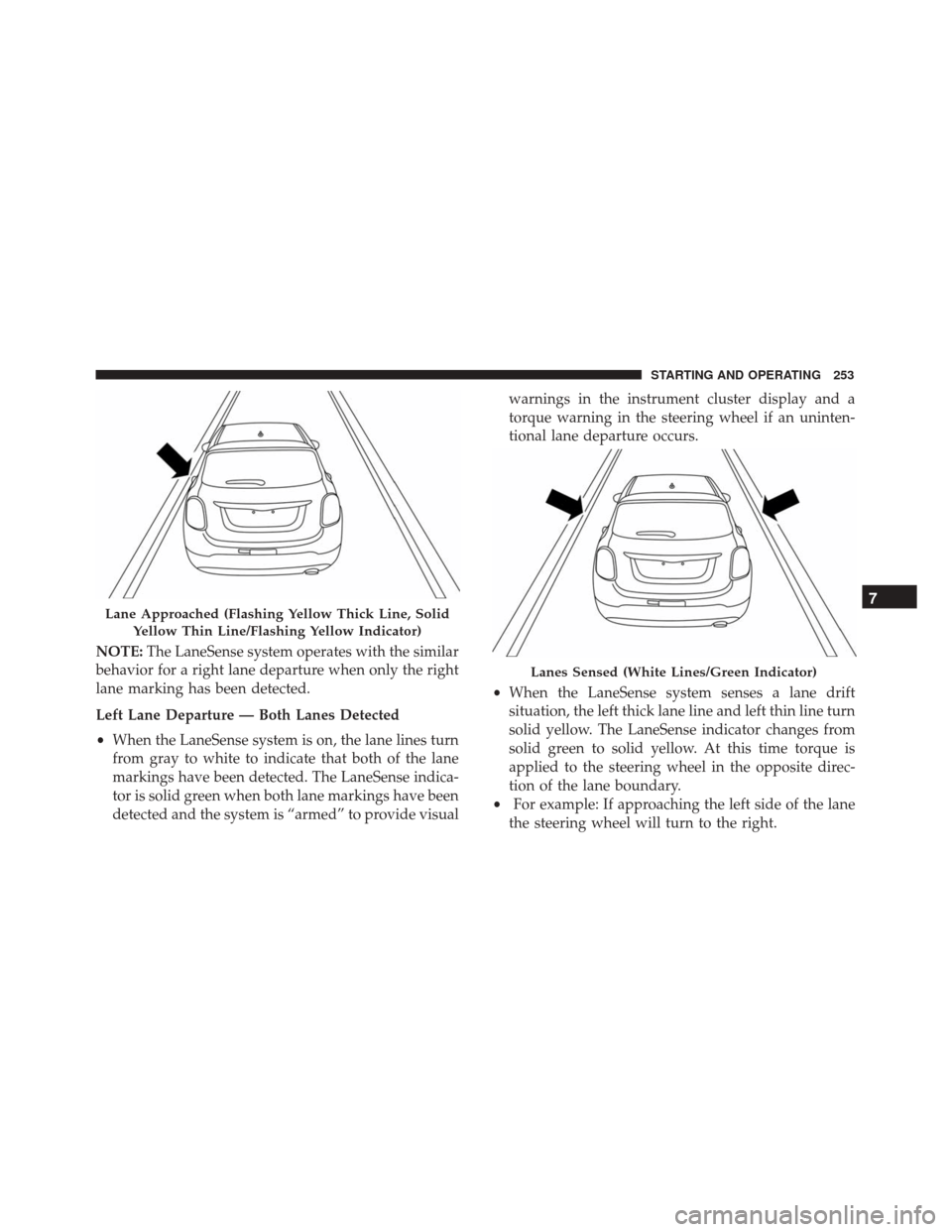
• When the LaneSense system senses a lane drift
situation, the left thick lane line and left thin line turn
solid yellow. The LaneSense indicator changes from
solid green to solid yellow. At this time torque is
applied to the steering wheel in the opposite direc-
tion of the lane boundary.
• For example: If approaching the left side of the lane
the steering wheel will turn to the right.
Lane Approached (Flashing Yellow Thick Line, Solid
Yellow Thin Line/Flashing Yellow Indicator)
Lanes Sensed (White Lines/Green Indicator)
7
STARTING AND OPERATING 253
Page 256 of 476

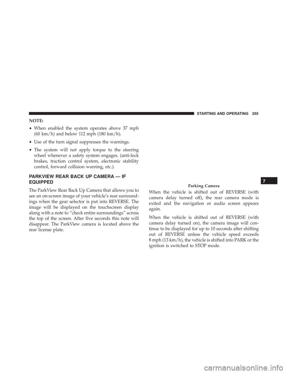
•When the LaneSense system senses the lane has been
approached and is in a lane departure situation, the
left thick lane line flashes yellow (on/off) and the left
thin line remains solid yellow. The LaneSense indi-
cator changes from solid yellow to flashing yellow.
At this time torque is applied to the steering wheel in
the opposite direction of the lane boundary.
• For example: If approaching the left side of the lane
the steering wheel will turn to the right. NOTE:
The LaneSense system operates with the similar
behavior for a right lane departure.
Changing LaneSense Status
The LaneSense system has settings to adjust the inten-
sity of the torque warning and the warning zone
sensitivity (early/late) that you can configure through
the Uconnect system screen. Refer to “Uconnect Set-
tings” in “Multimedia” for further information.
Lane Sensed (Solid Yellow Thick Line, Solid Yellow
Thin Line/Solid Yellow Indicator)Lane Approached (Flashing Yellow Thick Line, SolidYellow Thin Line/Flashing Yellow Indicator)
254 STARTING AND OPERATING
Page 257 of 476

NOTE:
•When enabled the system operates above 37 mph
(60 km/h) and below 112 mph (180 km/h).
• Use of the turn signal suppresses the warnings.
• The system will not apply torque to the steering
wheel whenever a safety system engages. (anti-lock
brakes, traction control system, electronic stability
control, forward collision warning, etc.).
PARKVIEW REAR BACK UP CAMERA — IF
EQUIPPED
The ParkView Rear Back Up Camera that allows you to
see an on-screen image of your vehicle’s rear surround-
ings when the gear selector is put into REVERSE. The
image will be displayed on the touchscreen display
along with a note to “check entire surroundings” across
the top of the screen. After five seconds this note will
disappear. The ParkView camera is located above the
rear license plate. When the vehicle is shifted out of REVERSE (with
camera delay turned off), the rear camera mode is
exited and the navigation or audio screen appears
again.
When the vehicle is shifted out of REVERSE (with
camera delay turned on), the camera image will con-
tinue to be displayed for up to 10 seconds after shifting
out of REVERSE unless the vehicle speed exceeds
8 mph (13 km/h), the vehicle is shifted into PARK or the
ignition is switched to STOP mode.Parking Camera7
STARTING AND OPERATING 255
Page 324 of 476

NOTE:•Your vehicle may be equipped with a compact
spare tire or a limited — use spare tire. For further
information refer to “Tires — General Information”
in “Maintaining Your Vehicle”.
• For vehicles so equipped, do not attempt to install
a center cap or wheel cover on the compact spare.
8. Install the wheel bolts with the threaded end of the wheel bolt toward the wheel. Lightly tighten the
wheel bolts.
WARNING!
To avoid the risk of forcing the vehicle off the jack,
do not fully tighten the wheel bolts until the
vehicle has been lowered. Failure to follow this
warning may result in serious injury.
9. Lower the vehicle to the ground by turning the wheel bolt wrench counterclockwise.
10. Finish tightening the wheel bolts. Push down on the wrench while at the end of the handle for increased
leverage. Tighten the wheel bolts in a star pattern
until each wheel bolt has been tightened twice. Refer to “Torque Specifications” in “Technical Data”
for the proper lug bolt torque. If in doubt about the
correct tightness, have them checked with a torque
wrench by your authorized dealer or at a service
station.
11. Securely stow the jack, tools, chocks and flat tire.
WARNING!
A loose tire or jack thrown forward in a collision or
hard stop could endanger the occupants of the
vehicle. Always stow the jack parts and the spare
tire in the places provided. Have the deflated (flat)
tire repaired or replaced immediately.
Road Tire Installation
1. Mount the road tire on the axle.
2. Install the remaining wheel bolts with the threaded end of the wheel bolt toward the wheel. Lightly
tighten the wheel bolts.
322 IN CASE OF EMERGENCY
Page 325 of 476

WARNING!
To avoid the risk of forcing the vehicle off the jack,
do not tighten the lug nuts fully until the vehicle
has been lowered. Failure to follow this warning
may result in serious injury.
3. Lower the vehicle to the ground by turning the jack handle counterclockwise.
4. Finish tightening the wheel bolts. Push down on the wrench while at the end of the handle for increased
leverage. Tighten the wheel bolts in a star pattern
until each wheel bolt has been tightened twice. Refer
to “Torque Specifications” in the “Technical Data”
section for the proper lug bolt torque. If in doubt
about the correct tightness, have them checked with
a torque wrench by your authorized dealer or service
station.
5. Lower the jack until it is free. Remove the wheel chocks. Stow the jack and tools back in the proper
storage location. Release the Electric Park Brake
before driving the vehicle. 6. After 25 miles (40 km) check the wheel bolt torque
with a torque wrench to ensure that all wheel bolts
are properly seated against the wheel.
TIRE SERVICE KIT STORAGE
The Tire Service Kit is located in the rear storage
compartment inside a storage container. Located inside
the container are a screwdriver and the emergency fuel
funnel. To access the Tire Service Kit open the liftgate
and remove the load floor.
Tire Service Kit Location
8
IN CASE OF EMERGENCY 323
Page 373 of 476

Frequency Of Fluid Change
Under normal operating conditions, the fluid installed
at the factory will give satisfactory lubrication for the
life of the vehicle. Fluid changes are not necessary
unless lubricant has become contaminated with water.
NOTE:If contaminated with water, the fluid should be
changed immediately.
Automatic Transmission — If Equipped
Selection Of Lubricant
It is important to use the proper transmission fluid to
ensure optimum transmission performance and life.
Use only the manufacturer ’s specified transmission
fluid. Refer to “Fluids, Lubricants, And Genuine Parts”
in “Technical Data” for fluid specifications. It is impor-
tant to maintain the transmission fluid at the correct
level using the recommended fluid.
NOTE: No chemical flushes should be used in any
transmission; only the approved lubricant should be
used.
CAUTION!
Using a transmission fluid other than the manufac-
turer ’s recommended fluid may cause deterioration
in transmission shift quality and/or torque con-
verter shudder. Refer to “Fluids, Lubricants, And
Genuine Parts” in “Technical Data” for fluid speci-
fications.
Special Additives
The manufacturer strongly recommends against using
any special additives in the transmission. Automatic
Transmission Fluid (ATF) is an engineered product and
its performance may be impaired by supplemental
additives. Therefore, do not add any fluid additives to
the transmission. Avoid using transmission sealers as
they may adversely affect seals.
CAUTION!
Do not use chemical flushes in your transmission as
the chemicals can damage your transmission com-
ponents. Such damage is not covered by the New
Vehicle Limited Warranty.
9
MAINTAINING AND CARING FOR YOUR VEHICLE 371
Page 405 of 476
TECHNICAL DATA
CONTENTS
�VEHICLE IDENTIFICATION NUMBER ......404
� WHEEL AND TIRE TORQUE
SPECIFICATIONS .....................404
▫ Torque Specifications ..................405
� FLUID CAPACITIES ...................407 �
FLUIDS, LUBRICANTS, AND GENUINE
PARTS ............................ .408
▫ Engine ........................... .408
▫ Chassis .......................... .409
10