2014 FIAT 500 ABARTH instrument panel
[x] Cancel search: instrument panelPage 6 of 88

DRIVER COCKPIT
1. Turn Signal/Lights Lever (behind steering wheel) pg. 20
2. Boost Gauge/Shift Up Indicator
3. Instrument Cluster pg. 6
4. Electronic Vehicle Information Center (EVIC) Display
5. Electronic Vehicle Information Center (EVIC) Controls pg. 44
6. Wiper/Washer Lever pg. 22
7. Sport Mode pg. 28
8. Audio System pg. 34
9. Switch Panel
• Heated Seat Switches
• Electronic Stability Control (ESC) OFF pg. 49
• Hazard Switch
CONTROLS AT A GLANCE
4
Page 14 of 88

WARNING!
• Relying on the air bags alone could lead to more severe injuries in a collision.
The air bags work with your seat belt to restrain you properly. In some colli-
sions, the air bags won't deploy at all. Always wear your seat belts even
though you have air bags.
• Being too close to the steering wheel or instrument panel during Advanced
Front Air Bag deployment could cause serious injury, including death. Air
bags need room to inflate. Sit back, comfortably extending your arms to
reach the steering wheel or instrument panel.
• Supplemental Side Air Bag Inflatable Curtains and Supplemental Seat-
Mounted Side Air Bags need room to inflate. Do not lean against the door or
window. Sit upright in the center of the seat.
• Being too close to the Supplemental Side Air Bag Inflatable Curtain and/or
Seat-Mounted Side Air Bag during deployment could cause you to be se-
verely injured or killed.
• Do not drive your vehicle after the air bags have deployed. If you are involved
in another collision, the air bags will not be in place to protect you.
• After any collision, the vehicle should be taken to an authorized dealer imme-
diately.
CHILD RESTRAINTS
• Children 12 years or younger should ride properly buckled up in a rear seat, if
available. According to crash statistics, children are safer when properly re-
strained in the rear seats rather than in the front.
• Every state in the United States and all Canadian provinces require that small chil-
dren ride in proper restraint systems. This is the law, and you can be prosecuted
for ignoring it.
NOTE:
• For additional information, refer to www.seatcheck.org or call
1–866–SEAT-CHECK (1–866–732–8243).
•Canadian residents, should refer to Transport Canada’s website for additional informa-
tion: http://www.tc.gc.ca/eng/roadsafety/safedrivers-childsafety-index-53.htm
GETTING STARTED
12
Page 42 of 88

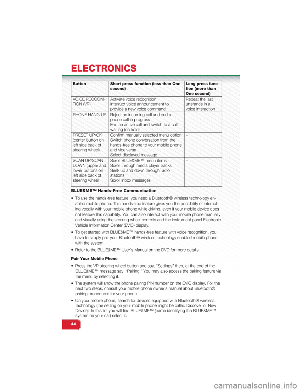
Button Short press function (less than Onesecond)Long press func-tion (more thanOne second)
VOICE RECOGNI-TION (VR)Activate voice recognitionInterrupt voice announcement toprovide a new voice command
Repeat the lastutterance in avoice interaction
PHONE HANG UP Reject an incoming call and end aphone call in progressEnd an active call and switch to a callwaiting (on hold)
–
PRESET UP/OK(center button onleft side back ofsteering wheel)
Confirm manually selected menu optionSwitch phone conversation from thehands-free phone to your mobile phoneand vice versaSelect displayed message
–
SCAN UP/SCANDOWN (upper andlower buttons onleft side back ofsteering wheel
Scroll BLUE&ME™ menu itemsScroll through media player tracksSeek up and down through radiostationsScroll inbox messages
–
BLUE&ME™ Hands-Free Communication
• To use the hands-free feature, you need a Bluetooth® wireless technology en-
abled mobile phone. This hands-free feature gives you the possibility of interact-
ing vocally with your mobile phone while driving, even if your mobile device does
not feature this capability. You can also interact with your mobile phone manually
and visually using the steering wheel controls and the instrument panel Electronic
Vehicle Information Center (EVIC) display.
• To get started with BLUE&ME™ hands-free feature with voice recognition, you
have to simply pair your Bluetooth® wireless technology enabled mobile phone
with the system.
• Refer to the BLUE&ME™ User's Manual on the DVD for more details.
Pair Your Mobile Phone
• Press the VR steering wheel button and say, “Settings” then, at the end of the
BLUE&ME™ message say, “Pairing.” You may also access the pairing feature via
the menu by selecting it.
• The system will show the phone pairing PIN number on the EVIC display. For the
next two steps, consult your mobile phone owner’s manual about Bluetooth®
pairing procedures for your phone.
• On your mobile phone, search for devices equipped with Bluetooth® wireless
technology (the setting on your mobile phone might be called Discover or New
Device). In this list you will find BLUE&ME™ (name identifying the BLUE&ME™
system on your car) select it.
ELECTRONICS
40
Page 59 of 88

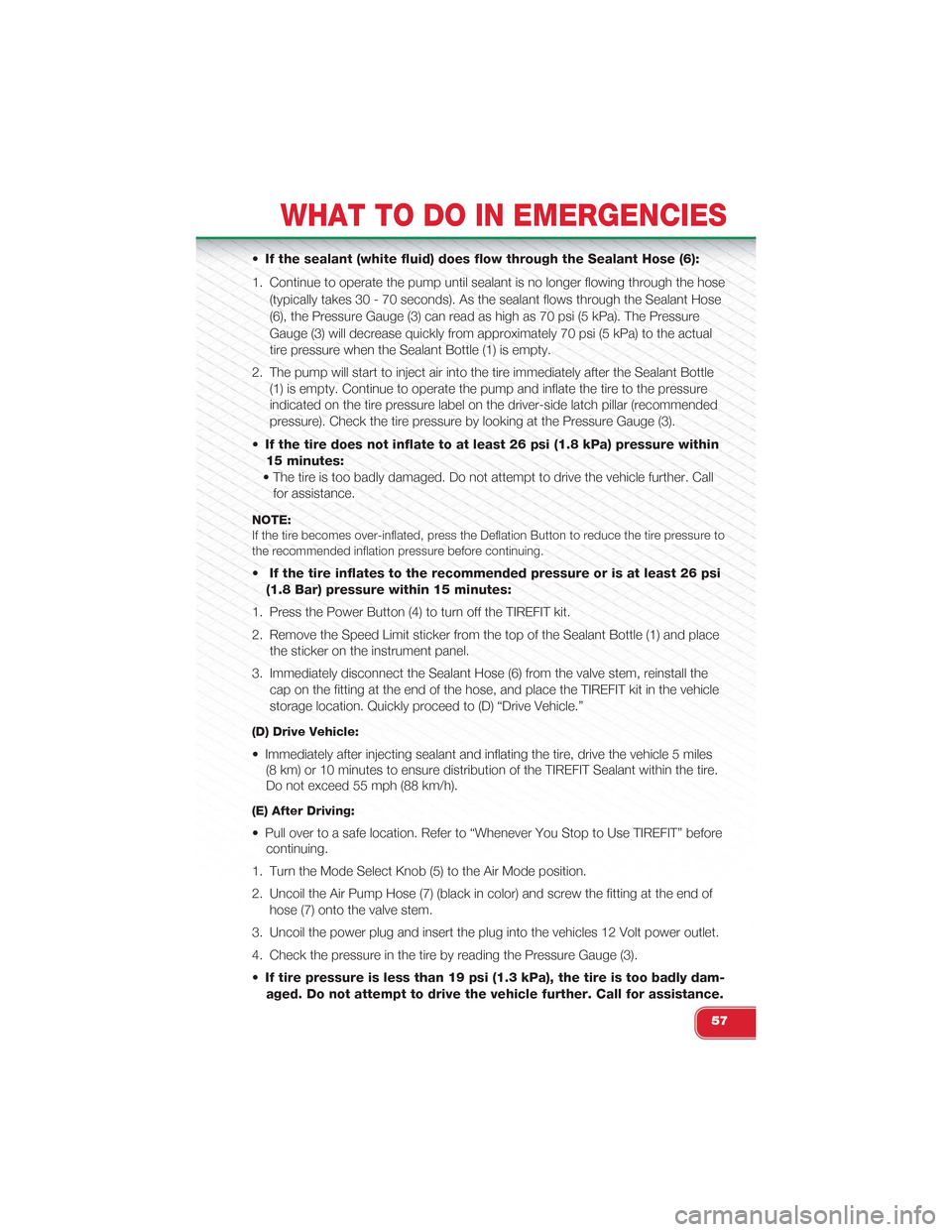
•If the sealant (white fluid) does flow through the Sealant Hose (6):
1. Continue to operate the pump until sealant is no longer flowing through the hose
(typically takes 30 - 70 seconds). As the sealant flows through the Sealant Hose
(6), the Pressure Gauge (3) can read as high as 70 psi (5 kPa). The Pressure
Gauge (3) will decrease quickly from approximately 70 psi (5 kPa) to the actual
tire pressure when the Sealant Bottle (1) is empty.
2. The pump will start to inject air into the tire immediately after the Sealant Bottle
(1) is empty. Continue to operate the pump and inflate the tire to the pressure
indicated on the tire pressure label on the driver-side latch pillar (recommended
pressure). Check the tire pressure by looking at the Pressure Gauge (3).
•If the tire does not inflate to at least 26 psi (1.8 kPa) pressure within
15 minutes:
• The tire is too badly damaged. Do not attempt to drive the vehicle further. Call
for assistance.
NOTE:If the tire becomes over-inflated, press the Deflation Button to reduce the tire pressure tothe recommended inflation pressure before continuing.
•If the tire inflates to the recommended pressure or is at least 26 psi
(1.8 Bar) pressure within 15 minutes:
1. Press the Power Button (4) to turn off the TIREFIT kit.
2. Remove the Speed Limit sticker from the top of the Sealant Bottle (1) and place
the sticker on the instrument panel.
3. Immediately disconnect the Sealant Hose (6) from the valve stem, reinstall the
cap on the fitting at the end of the hose, and place the TIREFIT kit in the vehicle
storage location. Quickly proceed to (D) “Drive Vehicle.”
(D) Drive Vehicle:
• Immediately after injecting sealant and inflating the tire, drive the vehicle 5 miles
(8 km) or 10 minutes to ensure distribution of the TIREFIT Sealant within the tire.
Do not exceed 55 mph (88 km/h).
(E) After Driving:
• Pull over to a safe location. Refer to “Whenever You Stop to Use TIREFIT” before
continuing.
1. Turn the Mode Select Knob (5) to the Air Mode position.
2. Uncoil the Air Pump Hose (7) (black in color) and screw the fitting at the end of
hose (7) onto the valve stem.
3. Uncoil the power plug and insert the plug into the vehicles 12 Volt power outlet.
4. Check the pressure in the tire by reading the Pressure Gauge (3).
•If tire pressure is less than 19 psi (1.3 kPa), the tire is too badly dam-
aged. Do not attempt to drive the vehicle further. Call for assistance.
WHAT TO DO IN EMERGENCIES
57
Page 65 of 88

• After the event occurs, when the system is active, the message "Fuel Cutoff See
Handbook" is displayed.
• Carefully check the vehicle for fuel leaks in the engine compartment and on the
ground near the engine compartment and fuel tank before resetting the system
and starting the engine.
NOTE:
In order to start the engine and move the vehicle to a safe location after an impact, the
System Reset Procedure must be completed.
System Reset Procedure
• After an impact causing air bag deployment, the left and right turn signal lights,
located in the instrument panel cluster, will both be blinking until the ignition is
turned off.
• In order to move your vehicle to the side of the road you must follow the system
reset procedure.
Customer Action Customer Will See
1. Turn ignition OFF. (Turn SignalSwitch must be placed in NeutralState).
2. Turn ignition ON. Left Turn Light is OFF. Right Turn LightBLINKS.
3. Turn Right Turn Signal Switch ON. Right Turn Light is ON SOLID. Left TurnLight BLINKS.
4. Turn Left Turn Signal Switch ON. Left Turn Light is ON SOLID. Right TurnLight BLINKS.
5. Turn Right Turn Signal Switch ON. Right Turn Light is ON SOLID. Left TurnLight BLINKS.
6. Turn Left Turn Signal Switch ON. Left Turn Light is ON SOLID. Right TurnLight is ON SOLID.
7. Turn Left Turn Signal Switch OFF.(Turn Signal Switch must be placed inNeutral State).
Left Turn Light is OFF. Right Turn Lightis OFF.
8. Turn ignition OFF. System is now reset and the enginemay be started.
9. Turn Hazard Flashers OFF (manually).
• If a reset procedure step is not completed within 45 seconds, then the turn signal
lights will turn off and the reset procedure must be performed again in order to be
successful.
WHAT TO DO IN EMERGENCIES
63
Page 68 of 88

OPENING THE HOOD
• Pull the red release lever located be-
low the instrument panel and in front
of the driver’s door.
•Raise the hood and locate the safety
latch in the middle of the hood opening.
• Move the safety latch while lifting the
hood at the same time.
• Insert the support rod into the slot on
the hood.
• To close the hood, remove the sup-
port rod and place it in the retaining
clip, then lower the hood slowly.
WARNING!
Be sure the hood is fully latched before driving your vehicle. If the hood is not fully
latched, it could open when the vehicle is in motion and block your vision. Failure
to follow this warning could result in serious injury or death.
MAINTAINING YOUR VEHICLE
66
Page 75 of 88

FUSES
Interior Fuses
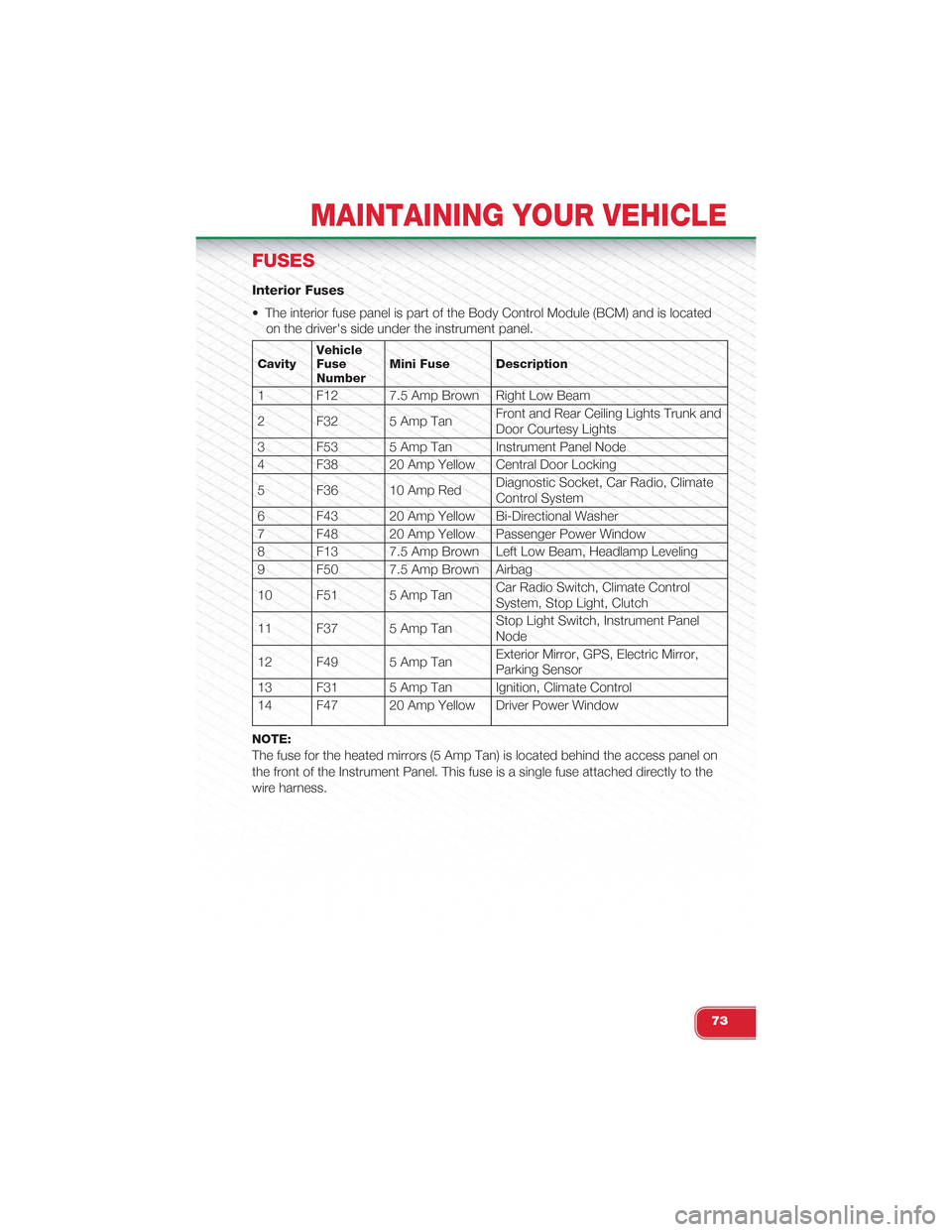
• The interior fuse panel is part of the Body Control Module (BCM) and is located
on the driver's side under the instrument panel.
CavityVehicleFuseNumberMini Fuse Description
1 F12 7.5 Amp Brown Right Low Beam
2 F32 5 Amp TanFront and Rear Ceiling Lights Trunk andDoor Courtesy Lights
3 F53 5 Amp Tan Instrument Panel Node
4 F38 20 Amp Yellow Central Door Locking
5 F36 10 Amp RedDiagnostic Socket, Car Radio, ClimateControl System
6 F43 20 Amp Yellow Bi-Directional Washer
7 F48 20 Amp Yellow Passenger Power Window
8 F13 7.5 Amp Brown Left Low Beam, Headlamp Leveling
9 F50 7.5 Amp Brown Airbag
10 F51 5 Amp TanCar Radio Switch, Climate ControlSystem, Stop Light, Clutch
11 F37 5 Amp TanStop Light Switch, Instrument PanelNode
12 F49 5 Amp TanExterior Mirror, GPS, Electric Mirror,Parking Sensor
13 F31 5 Amp Tan Ignition, Climate Control
14 F47 20 Amp Yellow Driver Power Window
NOTE:
The fuse for the heated mirrors (5 Amp Tan) is located behind the access panel on
the front of the Instrument Panel. This fuse is a single fuse attached directly to the
wire harness.
MAINTAINING YOUR VEHICLE
73