Page 417 of 508

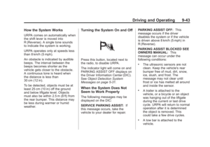
Black plate (63,1)Cadillac Escalade/Escalade ESV Owner Manual (GMNA-Localizing-U.S./
Canada/Mexico-6081529) - 2014 - CRC 1st Edition - 4/23/13
Vehicle Care 10-63
Check the tire sealant expiration
date on the sealant canister. The
sealant canister should be replaced
before its expiration date.
Replacement sealant canisters are
available at your local dealer. See
“Removal and Installation of the
Sealant Canister”following.
There is only enough sealant to seal
one tire. After usage, the sealant
canister and sealant/air hose
assembly must be replaced. See
“Removal and Installation of the
Sealant Canister” following.
Using the Tire Sealant and
Compressor Kit to Temporarily
Seal and Inflate a
Punctured Tire
Follow the directions closely for
correct sealant usage.
When using the tire sealant and
compressor kit during cold
temperatures, warm the kit in a
heated environment for five minutes.
This will help to inflate the tire
faster.
If a tire goes flat, avoid further tire
and wheel damage by driving slowly
to a level place. Turn on the hazard
warning flashers.
SeeIf a Tire Goes Flat on
page 10-60 for other important
safety warnings.
Do not remove any objects that
have penetrated the tire. 1. Remove the tire sealant and
compressor kit from its storage
location. See Storing the Tire
Sealant and Compressor Kit on
page 10-68.
Make sure the on/off button (D)
is in the off (O) position.
2. Unwrap the sealant/air hose (G) and the power plug (C).
3. Place the kit on the ground. Make sure the tire valve stem is
positioned close to the ground
so the hose will reach it.
4. Remove the valve stem cap from the flat tire by turning it
counterclockwise.
5. Attach the sealant/air hose (G) onto the tire valve stem. Turn it
clockwise until it is tight.
Page 418 of 508

Black plate (64,1)Cadillac Escalade/Escalade ESV Owner Manual (GMNA-Localizing-U.S./
Canada/Mexico-6081529) - 2014 - CRC 1st Edition - 4/23/13
10-64 Vehicle Care
6. Plug the power plug (C) into theaccessory power outlet in the
vehicle. Unplug all items from
other accessory power outlets.
See Power Outlets on page 5-6
in the owner manual.
If the vehicle has an accessory
power outlet, do not use the
cigarette lighter.
If the vehicle only has a cigarette
lighter, use the cigarette lighter.
Do not pinch the power plug
cord in the door or window.
7. Start the vehicle. The vehicle must be running while using the
air compressor.
8. Press the on/off (D) button to turn the tire sealant and
compressor kit on.
The compressor will inject
sealant and air into the tire.
The pressure gauge (E) will
initially show a high pressure
while the compressor pushes the
sealant into the tire. Once the
sealant is completely dispersed into the tire, the pressure will
quickly drop and start to rise
again as the tire inflates with
air only.
9. Inflate the tire to the recommended inflation pressure
using the pressure gauge (E).
The recommended inflation
pressure can be found on the
Tire and Loading Information
label. See Tire Pressure on
page 10-46.
The pressure gauge (E) may
read higher than the actual tire
pressure while the compressor is
on. Turn the compressor off to
get an accurate pressure
reading. The compressor may
be turned on/off until the correct
pressure is reached.
Notice: If the recommended
pressure cannot be reached after
approximately 25 minutes, the
vehicle should not be driven
farther. The tire is too severely
damaged and the tire sealant and
compressor kit cannot inflate the tire. Remove the power plug from
the accessory power outlet and
unscrew the inflating hose from
the tire valve. See
Roadside
Service on page 13-5.
10. Press the on/off button (D) to turn the tire sealant and
compressor kit off.
The tire is not sealed and will
continue to leak air until the
vehicle is driven and the
sealant is distributed in the tire,
therefore, Steps 11 through
17 must be done immediately
after Step 10.
Be careful while handling the
tire sealant and compressor kit
as it could be warm after
usage.
11. Unplug the power plug (C) from the accessory power outlet in
the vehicle.
12. Turn the sealant/air hose (G) counterclockwise to remove it
from the tire valve stem.
Page 419 of 508

Black plate (65,1)Cadillac Escalade/Escalade ESV Owner Manual (GMNA-Localizing-U.S./
Canada/Mexico-6081529) - 2014 - CRC 1st Edition - 4/23/13
Vehicle Care 10-65
13. Replace the tire valvestem cap.
14. Replace the sealant/air hose (G), and the power plug (C)
back in their original location.
15. If the flat tire was able to inflateto the recommended inflation
pressure, remove the
maximum speed label from the
tire sealant canister (B) and
place it in a highly visible
location.
Do not exceed the speed on
this label until the damaged tire
is repaired or replaced.
16. Return the equipment to its original storage location in the
vehicle. 17. Immediately drive the vehicle
8 km (5 mi) to distribute the
sealant in the tire.
18. Stop at a safe location and check the tire pressure. Refer
to Steps 1 through 11 under
“Using the Tire Sealant and
Compressor Kit without Sealant
to Inflate a Tire (Not
Punctured).”
If the tire pressure has fallen
more than 68 kPa (10 psi)
below the recommended
inflation pressure, stop driving
the vehicle. The tire is too
severely damaged and the tire
sealant cannot seal the tire.
SeeRoadside Service on
page 13-5.
If the tire pressure has not
dropped more than 68 kPa
(10 psi) from the recommended
inflation pressure, inflate the
tire to the recommended
inflation pressure.
19. Wipe off any sealant from the wheel, tire or vehicle. 20. Dispose of the used tire
sealant canister (B) and
sealant/air hose (G) assembly
at a local dealer or in
accordance with local
regulations and practices.
21. Replace it with a new canister available from your dealer.
22. After temporarily sealing a tire using the tire sealant and
compressor kit, take the
vehicle to an authorized dealer
within a 161 km (100 mi) of
driving to have the tire repaired
or replaced.
Page 420 of 508

Black plate (66,1)Cadillac Escalade/Escalade ESV Owner Manual (GMNA-Localizing-U.S./
Canada/Mexico-6081529) - 2014 - CRC 1st Edition - 4/23/13
10-66 Vehicle Care
Using the Tire Sealant and
Compressor Kit without
Sealant to Inflate a Tire (Not
Punctured)
To use the air compressor to inflate
a tire with air only and not sealant:
If a tire goes flat, avoid further tire
and wheel damage by driving slowly
to a level place. Turn on the hazard
warning flashers.
SeeIf a Tire Goes Flat on
page 10-60 for other important
safety warnings. 1. Remove the tire sealant and
compressor kit from its storage
location. See Storing the Tire
Sealant and Compressor Kit on
page 10-68.
2. Unlock the air only hose (F) from the tire sealant canister (B) by
pulling up on the lever.
3. Pull the air only hose (F) from the tire sealant canister (B).
4. Remove the power plug (C) from the air compressor (A).
5. Place the kit on the ground.
Make sure the tire valve stem is
positioned close to the ground
so the hose will reach it.
6. Remove the tire valve stem cap by turning it counterclockwise.
7. Attach the air only hose (F) onto the tire valve stem and press the
lever down to secure it. 8. Plug the power plug (C) into the
accessory power outlet in the
vehicle. Unplug all items from
other accessory power outlets.
See Power Outlets on page 5-6
in the owner manual.
If the vehicle has an accessory
power outlet, do not use the
cigarette lighter.
If the vehicle only has a cigarette
lighter, use the cigarette lighter.
Do not pinch the power plug
cord in the door or window.
9. Start the vehicle. The vehicle must be running while using the
air compressor.
10. Press the on/off (D) button to turn the compressor on.
The compressor will inflate the
tire with air only.
Page 421 of 508

Black plate (67,1)Cadillac Escalade/Escalade ESV Owner Manual (GMNA-Localizing-U.S./
Canada/Mexico-6081529) - 2014 - CRC 1st Edition - 4/23/13
Vehicle Care 10-67
11. Inflate the tire to therecommended inflation
pressure using the pressure
gauge (E). The recommended
inflation pressure can be found
on the Tire and Loading
Information label. See Tire
Pressure on page 10-46.
The pressure gauge (E) may
read higher than the actual tire
pressure while the compressor
is on. Turn the compressor off
to get an accurate reading. The
compressor may be turned on/
off until the correct pressure is
reached.
12. Press the on/off button (D) to turn the tire sealant and
compressor kit off.
Be careful while handling the
tire sealant and compressor kit
as it could be warm after
usage.
13. Unplug the power plug (C) from the accessory power outlet in
the vehicle. 14. Disconnect the air only
hose (F) from the tire valve
stem, by turning it
counterclockwise, and replace
the tire valve stem cap.
15. Replace the air only hose (F) and the power plug (C) back in
its original location.
16. Place the equipment in the original storage location in the
vehicle.
Removal and Installation of the
Sealant Canister
To remove the sealant canister:
1. Unlock the air only hose (F) fromthe tire sealant canister (B) by
pulling up on the lever. 2. Pull the air only hose (F) from
the tire sealant canister (B).
3. Unwrap the sealant/air hose (G) from the compressor (A).
4. Turn the tire sealant canister (B)so the inflator filling hose is
aligned with the slot in the
compressor.
5. Lift the tire sealant canister (B) from the compressor and
replace with a new sealant
canister. See your dealer for
more information.
Page 422 of 508

Black plate (68,1)Cadillac Escalade/Escalade ESV Owner Manual (GMNA-Localizing-U.S./
Canada/Mexico-6081529) - 2014 - CRC 1st Edition - 4/23/13
10-68 Vehicle Care
To install a new sealant canister:
1. Align the sealant/air hose (G)with the slot in the air
compressor.
2. Push the tire sealant canister (B) down and turn it clockwise.
3. Wrap the sealant/air hose (G) around the air compressor
channel to stow it in its original
location.
4. Push the air only hose (F) onto the sealant canister inlet and
push the lever down.
Storing the Tire Sealant
and Compressor Kit
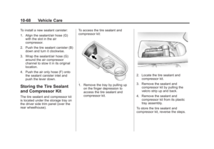
The tire sealant and compressor kit
is located under the storage tray on
the driver side trim panel (over the
rear wheelhouse). To access the tire sealant and
compressor kit:
1. Remove the tray by pulling up
on the finger depression to
access the tire sealant and
compressor kit.
2. Locate the tire sealant and
compressor kit.
3. Remove the sealant and compressor kit by pulling the
velcro strip up and back.
4. Remove the sealant and compressor kit from its plastic
tray assembly.
To store the tire sealant and
compressor kit, reverse the steps.
Page 423 of 508

Black plate (69,1)Cadillac Escalade/Escalade ESV Owner Manual (GMNA-Localizing-U.S./
Canada/Mexico-6081529) - 2014 - CRC 1st Edition - 4/23/13
Vehicle Care 10-69
Tire Changing
Removing the Spare Tire and
Tools
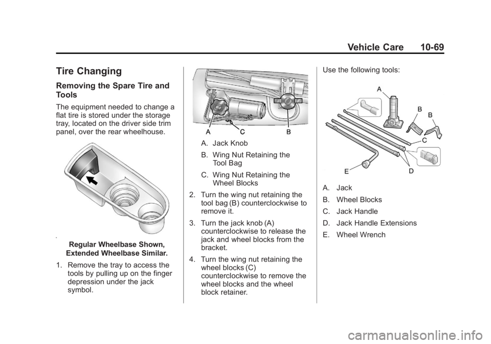
The equipment needed to change a
flat tire is stored under the storage
tray, located on the driver side trim
panel, over the rear wheelhouse.
Regular Wheelbase Shown,
Extended Wheelbase Similar.
1. Remove the tray to access the tools by pulling up on the finger
depression under the jack
symbol.
A. Jack Knob
B. Wing Nut Retaining theTool Bag
C. Wing Nut Retaining the Wheel Blocks
2. Turn the wing nut retaining the tool bag (B) counterclockwise to
remove it.
3. Turn the jack knob (A) counterclockwise to release the
jack and wheel blocks from the
bracket.
4. Turn the wing nut retaining the wheel blocks (C)
counterclockwise to remove the
wheel blocks and the wheel
block retainer. Use the following tools:
A. Jack
B. Wheel Blocks
C. Jack Handle
D. Jack Handle Extensions
E. Wheel Wrench
Page 424 of 508
Black plate (70,1)Cadillac Escalade/Escalade ESV Owner Manual (GMNA-Localizing-U.S./
Canada/Mexico-6081529) - 2014 - CRC 1st Edition - 4/23/13
10-70 Vehicle Care
To access the spare tire:
A. Hoist Assembly
B. Hoist Shaft
C. Hoist Shaft Access Cover/Hole
D. Jack Handle Extensions
E. Wheel Wrench
F. Hoist Cable
G. Tire/Wheel Retainer
H. Spare Tire (Valve StemPointed Down)
I. Hoist Shaft Access Hole J. Hoist End of Extension Tool
K. Spare Tire Lock
1. To reach the hoist shaft access
cover (C), remove the hitch
cover by turning the two
fasteners located at the bottom
of the cover counterclockwise
and then pull the cover down
and rotate it towards you.
2. Open the hoist shaft accesscover on the bumper to access
the spare tire lock. 3. To remove the spare tire lock
insert the ignition key, turn it
clockwise and then pull the
lock out.
4. Assemble the two jack handle
extensions (D) and wheel
wrench (E), as shown.