Page 129 of 208

Switching the system on/off
Switching off Press and hold the left button until the
control switches off.
Switching on
Press any button except:▷ALL program.▷Rear window defroster.▷Left side of Air volume button.▷Seat heating.
Microfilter/activated-charcoal filter
In external and recirculated air mode the mi‐
crofilter/activated charcoal filter filters dust,
pollen, and gaseous pollutants out of the air.
This filter should be replaced during scheduled
maintenance, refer to page 172, of your vehi‐
cle.
Ventilation
Front ventilation
▷Lever for changing the air flow direction,
arrow 1.▷Thumbwheels for opening and closing the
vents continuously, arrows 2.▷Thumbwheel to vary the temperature, ar‐
row 3.
Toward blue: colder.Toward red: warmer.
Adjusting the ventilation
▷Ventilation for cooling:
Adjust the vent to direct the air in your di‐
rection, such as if the vehicle interior is hot
from the sun.▷Draft-free ventilation:
Adjust the vent to let the air flow past you.
Ventilation in the rear
▷Thumbwheel for continuous opening and
closing of the vents, arrow 1.▷Thumbwheel to vary the temperature, ar‐
row 2.
Toward blue: colder.
Toward red: warmer.▷Lever for changing the air flow direction,
arrow 3.
Parked-car ventilation
The concept The parked-car ventilation ventilates the vehi‐
cle interior and lowers its temperature, if nec‐
essary.
The system can be switched on and off at any
external temperature, either directly or by us‐
ing two preset switch-on times. It remains
switched on for 30 minutes.
Open the vents to allow air to flow out.
Seite 129Climate controlControls129
Online Edition for Part no. 01 40 2 911 041 - VI/13
Page 130 of 208
Operation can be performed via iDrive.Switching on/off directly1."Settings"2."Climate"3."Activate comf. ventilation"
The symbol on the automatic climate con‐
trol flashes if the system is switched on.
Preselecting the switch-on time
1."Settings"2."Climate"3."Timer 1:" or "Timer 2:"4.Set the desired time.
Activating the switch-on time
1."Settings"2."Climate"3."Activate timer 1" or "Activate timer 2"
The symbol on the automatic climate con‐
trol lights up when the switch-on time is acti‐
vated.
The symbol on the automatic climate con‐
trol flashes when the system has been
switched on.
The system will only be switched on within the
next 24 hours. After that, it needs to reacti‐
vated.
Seite 130ControlsClimate control130
Online Edition for Part no. 01 40 2 911 041 - VI/13
Page 131 of 208

Interior equipmentVehicle equipmentAll standard, country-specific and optional
equipment that is offered in the model series is
described in this chapter. Therefore, equip‐
ment is also described that is not available in a
vehicle, e. g., because of the selected optional
equipment or country variant. This also applies
for safety-related functions and systems.
Integrated universal remote
control
The conceptThe integrated universal remote control can
operate up to 3 functions of remote-controlled
systems such as garage door drives or lighting
systems. The integrated universal remote con‐
trol replaces up to 3 different hand-held trans‐
mitters. To operate the remote control, the
buttons on the interior rearview mirror must be
programmed with the desired functions. The
hand-held transmitter for the particular system
is required in order to program the remote con‐
trol.
During programming
During programming and before activat‐
ing a device using the integrated universal re‐
mote control, ensure that there are no people,
animals, or objects in the range of movement
of the remote-controlled device; otherwise,
there is a risk of injury or damage.
Also follow the safety instructions of the hand-
held transmitter.◀
Before selling the vehicle, delete the stored
functions for the sake of security.Compatibility
If this symbol is printed on the packag‐
ing or in the instructions of the system
to be controlled, the system is gener‐
ally compatible with the integrated universal
remote control.
If you have any questions, please contact:▷Your service center.▷www.homelink.com on the Internet.
HomeLink is a registered trademark of John‐
son Controls, Inc.
Controls on the interior rearview
mirror
▷LED, arrow 1.▷Buttons, arrow 2.▷The hand-held transmitter, arrow 3, is re‐
quired for programming.
Programming
General information
1.Switch on the ignition.2.Initial setup:
Press and hold the left and right button on
the interior rearview mirror simultaneously
for approximately 20 seconds until the LED
on the interior rearview mirror flashes. ThisSeite 131Interior equipmentControls131
Online Edition for Part no. 01 40 2 911 041 - VI/13
Page 132 of 208

erases all programming of the buttons on
the interior rearview mirror.3.Hold the hand-held transmitter for the sys‐
tem to be controlled approx. 1 to 3 in/2.5 to
8 cm away from the buttons on the interior
rearview mirror. The required distance de‐
pends on the manual transmitter.4.Simultaneously press and hold the button
of the desired function on the hand-held
transmitter and the button to be program‐
med on the interior rearview mirror. The
LED on the interior rearview mirror will be‐
gin flashing slowly.5.Release both buttons as soon as the LED
flashes more rapidly. When the LED is
flashing faster, this indicates that the but‐
ton on the interior rearview mirror has been
programmed.
If the LED does not flash faster after at
least 60 seconds, change the distance be‐
tween the interior rearview mirror and the
hand-held transmitter and repeat the step.
Several more attempts at different distan‐
ces may be necessary. Wait at least
15 seconds between attempts.
Canada: if programming with the hand-
held transmitter was interrupted, hold
down the interior rearview mirror button
and repeatedly press and release the
hand-held transmitter button for 2 sec‐
onds.6.To program other functions on other but‐
tons, repeat steps 3 to 5.
The systems can be controlled using the inte‐
rior rearview mirror buttons.
Special feature of the alternating-
code wireless system
If you are unable to operate the system after
repeated programming, please check if the
system to be controlled features an alternat‐
ing-code system.
Read the system's operating manual, or press
the programmed button on the interior rear‐
view mirror longer. If the LED on the interior
rearview mirror starts flashing rapidly and then
stays lit constantly for 2 seconds, the system
features an alternating-code system. Flashing
and continuous illumination of the LED will re‐
peat for approximately 20 seconds.
For systems with an alternating-code system,
the integrated universal remote control and the
system also have to be synchronized.
Please read the operating manual of the sys‐
tem being set up for information on how to
synchronize the system.
Synchronizing is easier with the aid of a sec‐
ond person.
To synchronize:1.Park the vehicle within range of the re‐
mote-controlled system.2.Program the relevant button on the interior
rearview mirror as described.3.Locate and press the synchronizing button
on the system being programmed. You
have approx. 30 seconds for the next step.4.Hold down the programmed button on the
interior rearview mirror for approximately
3 seconds and then release it. If necessary,
repeat this work step up to three times in
order to finish synchronization. Once syn‐
chronization is complete, the programmed
function will be carried out.
Reprogramming individual buttons
1.Switch on the ignition.2.Press and hold the interior rearview mirror
button to be programmed.3.As soon as the interior rearview mirror LED
starts flashing slowly, hold the hand-held
transmitter for the system to be controlled
approx. 1 to 3 in/2.5 to 8 cm away from the
buttons on the interior rearview mirror. The
required distance depends on the manual
transmitter.Seite 132ControlsInterior equipment132
Online Edition for Part no. 01 40 2 911 041 - VI/13
Page 133 of 208

4.Likewise, press and hold the button of the
desired function on the hand-held trans‐
mitter.5.Release both buttons as soon as the inte‐
rior rearview mirror LED flashes more rap‐
idly. When the LED is flashing faster, this
indicates that the button on the interior
rearview mirror has been programmed.
The system can then be controlled by the
button on the interior rearview mirror.
If the LED does not flash faster after at
least 60 seconds, change the distance and
repeat the step. Several more attempts at
different distances may be necessary. Wait
at least 15 seconds between attempts.
Canada: if programming with the hand-
held transmitter was interrupted, hold
down the interior rearview mirror button
and repeatedly press and release the
hand-held transmitter button for 2 sec‐
onds.
Controls
Before operation
Before operating a system using the
integrated universal remote control, ensure
that there are no people, animals, or objects
within the range of movement of the remote- controlled system; otherwise, there is a risk of
injury or damage.
Also follow the safety instructions of the hand-
held transmitter.◀
The system, such as the garage door, can be
operated using the button on the interior rear‐
view mirror while the engine is running or when
the ignition is started. To do this, hold down
the button within receiving range of the system
until the function is activated. The interior rear‐ view mirror LED stays lit while the wireless sig‐
nal is being transmitted.
Deleting stored functions Press and hold the left and right button on the
interior rearview mirror simultaneously for ap‐
proximately 20 seconds until the LED flashes
rapidly. All stored functions are deleted. The
functions cannot be deleted individually.
Connecting electrical
devices
Hints Do not plug chargers into the socket
Do not connect battery chargers to the
factory-installed sockets in the vehicle as this
may damage the battery.◀
Replace the cover after use
Reinsert the lighter or socket cover after
use, otherwise objects may get into the lighter
socket or fixture and cause a short circuit.◀
Sockets
Sockets can be used for the operation of elec‐
trical devices with the engine running or with
the ignition switched on. The total load of all
sockets must not exceed 140 watts at 12 volts.
Do not damage the socket by using unsuitable
connectors.
Front center console
Remove the cover.
Seite 133Interior equipmentControls133
Online Edition for Part no. 01 40 2 911 041 - VI/13
Page 134 of 208
Center armrest
Remove the cover.
Rear center console
Remove the cover.
In the cargo area
The socket is located on the right side in the
cargo area.
USB interface for data
transfer
The concept Connection for importing and exporting data
on USB devices, e.g.:▷Personal Profile settings, refer to page 34.▷Music collection, see user's manual for
Navigation, Entertainment and Communi‐
cation.▷Importing trips, see user's manual for Navi‐
gation, Entertainment, Communication.
Without Professional navigation
system or TV: at a glance
The USB interface is located in the glove com‐
partment.
With Professional navigation system
or TV: at a glance
The USB interface is located in the center arm‐
rest.
Seite 134ControlsInterior equipment134
Online Edition for Part no. 01 40 2 911 041 - VI/13
Page 135 of 208

Notes
Observe the following when connecting:▷Do not use force when plugging the con‐
nector into the USB interface.▷Do not connect devices such as fans or
lamps to the USB interface.▷Do not connect USB hard drives.▷Do not use the USB interface to recharge
external devices.
Cargo area
Cargo cover
Pull out the cargo cover, arrow 1, and hook
both sides into the brackets, arrow 2.
Hook the cargo cover on both sides
Hook the cargo cover on both sides to
prevent damaging the cover.◀
Do not deposit heavy objects
Do not deposit heavy or hard objects on
the trunk cover. Otherwise, they could endan‐
ger occupants during braking and evasive ma‐
neuvers, for example.◀
Do not let the trunk cover snap back into
place
Do not allow the trunk cover to snap back into
place; this can damage it.◀
Removing and inserting
Cargo cover without partition net:
Removing
The cover can be removed to load bulky lug‐
gage.
Reach under the cover and turn it upward, ar‐
rows. Pull the cover back horizontally.
Cargo cover with partition net:
Removing
The cover can be removed to load bulky lug‐
gage.
1.Press the button, arrow 1, to unlock the
cover.2.Pull the cover back, arrow 2.
Installing
Slide the cover forward horizontally into the
two side brackets until it audibly latches.
The red warning fields disappear in the case of
a cover with partition net.
Tug on the cover to check if it is properly
locked in place.
Seite 135Interior equipmentControls135
Online Edition for Part no. 01 40 2 911 041 - VI/13
Page 136 of 208

Enlarging the cargo area
General information
The cargo area can be enlarged by folding
down the rear seat backrest.
The rear seat backrest is divided into two parts
at a ratio of 60 to 40.
If equipped with through-loading system: the
rear seat backrest is divided in the ratio 40–20–
40. The sides and the middle section can be
folded down separately.
Hints Danger of pinching
Before folding down the rear seat back‐
rests, ensure that the area of movement of the
backrests is clear. In particular, ensure that no
one is located in the area of movement and
that no one reaches into the area of movement
of the rear seat backrests when the middle
section is folded down. Otherwise, injury or
damage may result.◀
Lock the rear seat backrests in position
Before mounting child restraint fixing
systems, place the seat backrest as far as pos‐
sible at an angle at which the child seat is rest‐
ing firmly against the backrest and all back‐
rests can be locked securely in place.
Otherwise, the child seat will not be as stable
as it should be, and there is increased danger
of injury due to unexpected movement of the
seat backrest.◀
Ensure that the lock is securely engaged
When folding back the backrest, be sure
that it locks in place securely. When this hap‐
pens the red warning field on the seat disap‐
pears. If it is not properly engaged, transported
cargo could enter the passenger compartment
during braking or evasive maneuvers and en‐
danger the vehicle occupants.◀Using the middle safety belt
If the middle safety belt in the rear is
used, the larger section of the backrest must
be locked. Otherwise, the safety belt will not
have a restraining effect.◀
Folding down the sides The right side can be folded down separately.
The left side can be folded down in combina‐
tion with the middle section.
Reach into the recess and pull forward.
Folding down the middle section
Reach into the recess and pull forward.
Partition net Do not let the partition net snap back into
place
Do not allow the partition net to snap back into
place; otherwise, there is a danger of injury and
the partition net could be damaged.◀
Seite 136ControlsInterior equipment136
Online Edition for Part no. 01 40 2 911 041 - VI/13
 1
1 2
2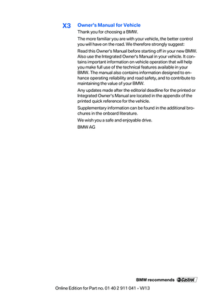 3
3 4
4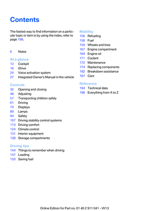 5
5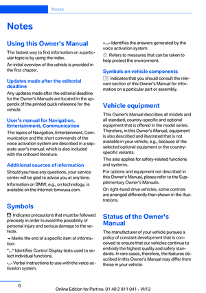 6
6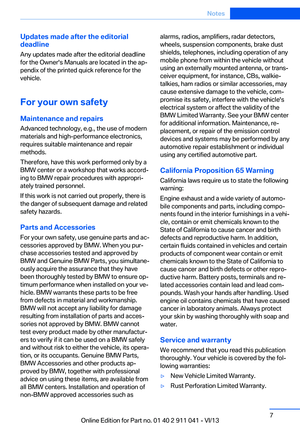 7
7 8
8 9
9 10
10 11
11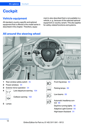 12
12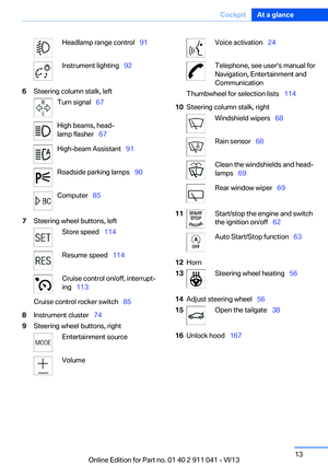 13
13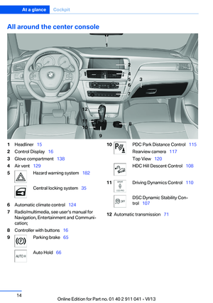 14
14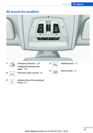 15
15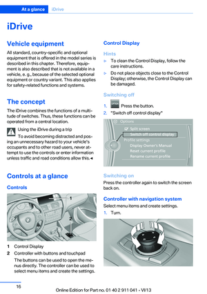 16
16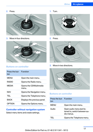 17
17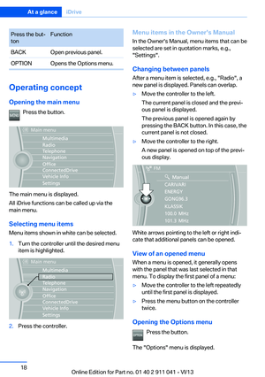 18
18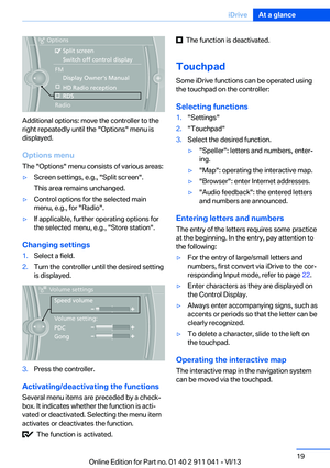 19
19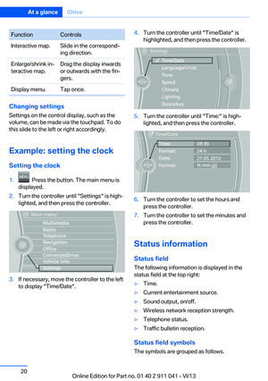 20
20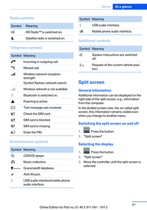 21
21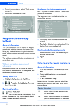 22
22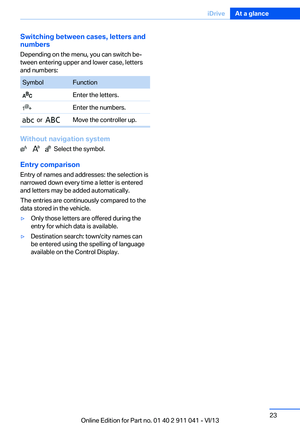 23
23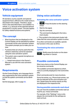 24
24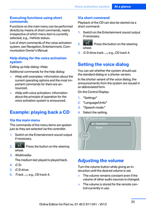 25
25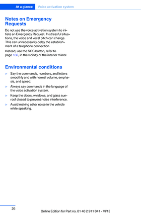 26
26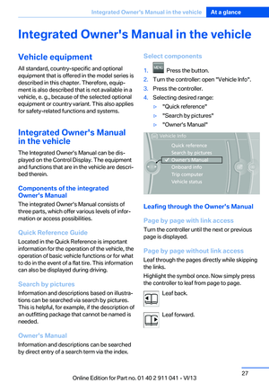 27
27 28
28 29
29 30
30 31
31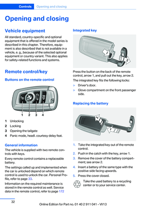 32
32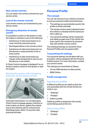 33
33 34
34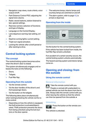 35
35 36
36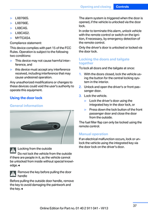 37
37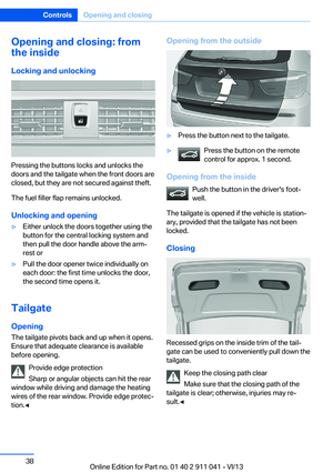 38
38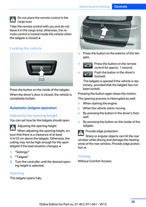 39
39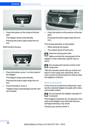 40
40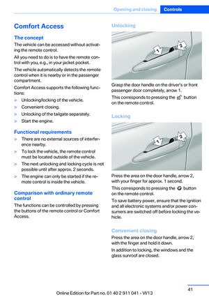 41
41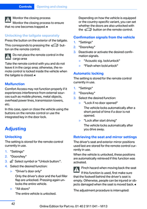 42
42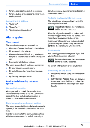 43
43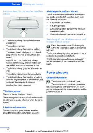 44
44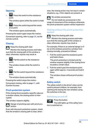 45
45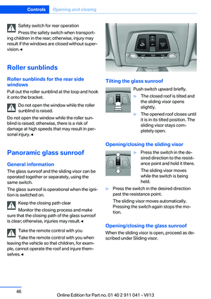 46
46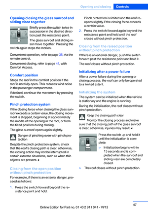 47
47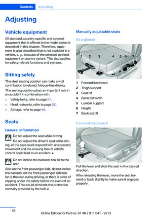 48
48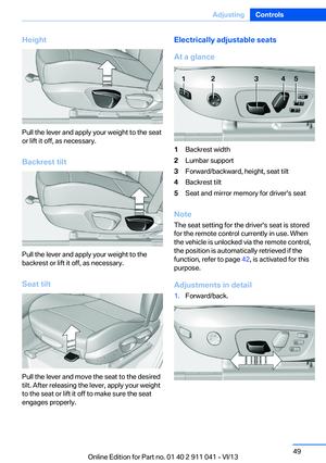 49
49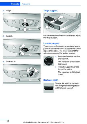 50
50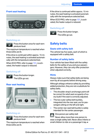 51
51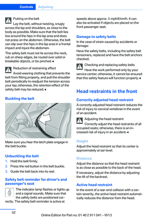 52
52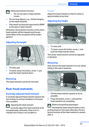 53
53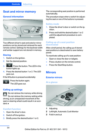 54
54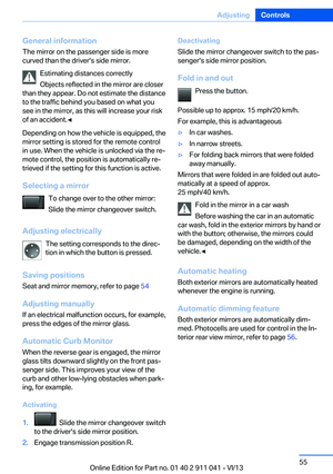 55
55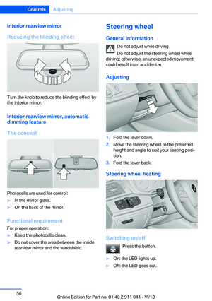 56
56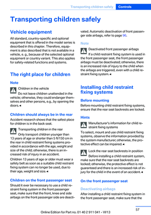 57
57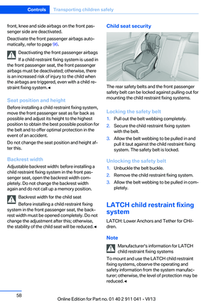 58
58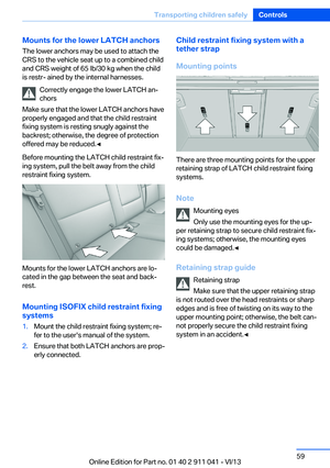 59
59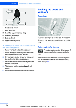 60
60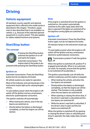 61
61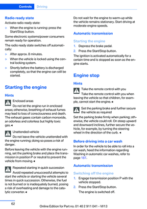 62
62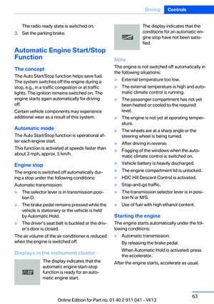 63
63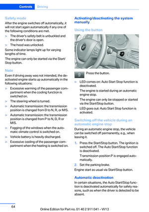 64
64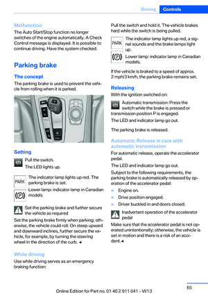 65
65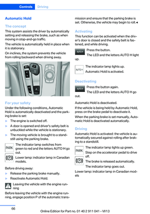 66
66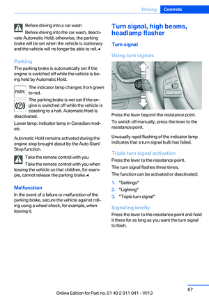 67
67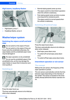 68
68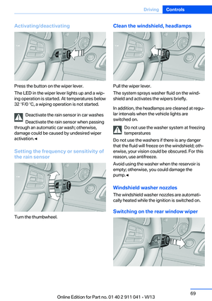 69
69 70
70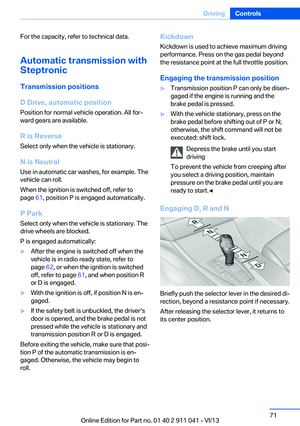 71
71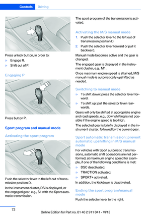 72
72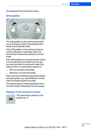 73
73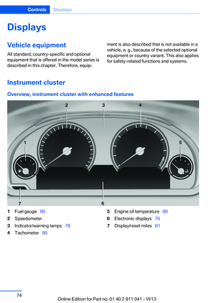 74
74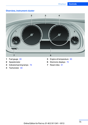 75
75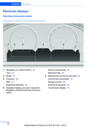 76
76 77
77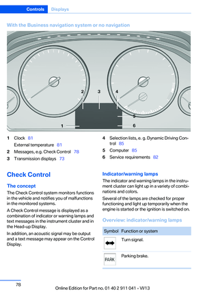 78
78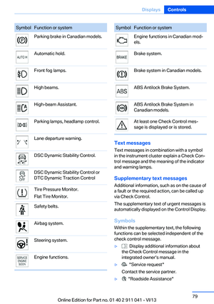 79
79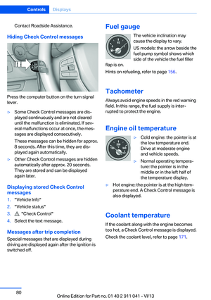 80
80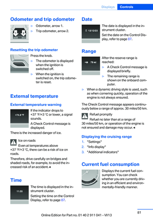 81
81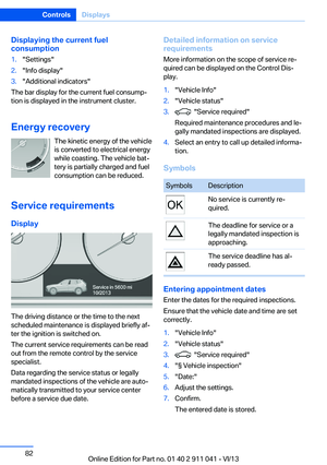 82
82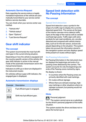 83
83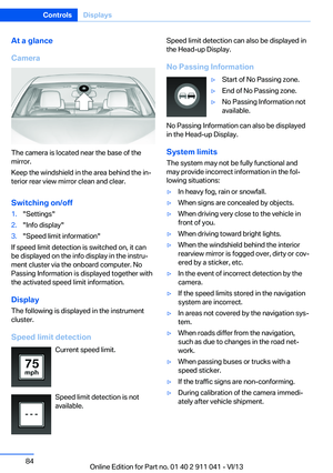 84
84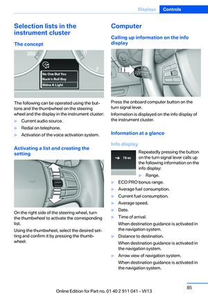 85
85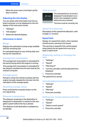 86
86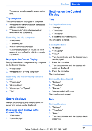 87
87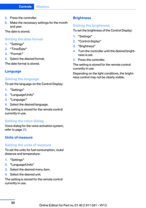 88
88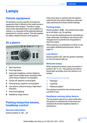 89
89 90
90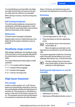 91
91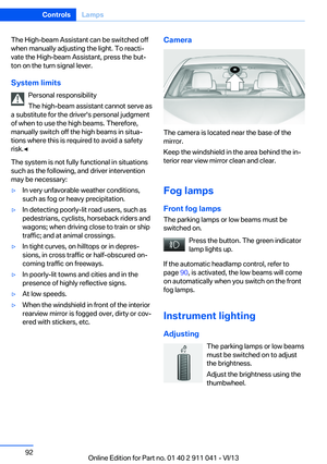 92
92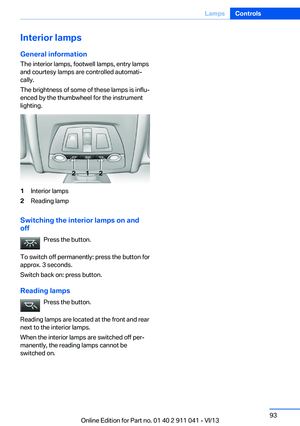 93
93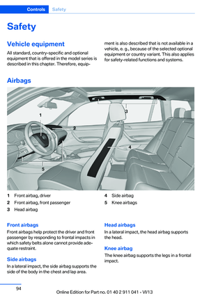 94
94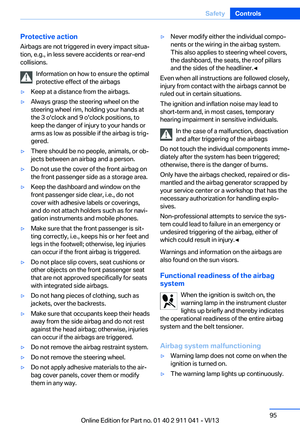 95
95 96
96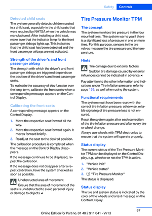 97
97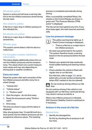 98
98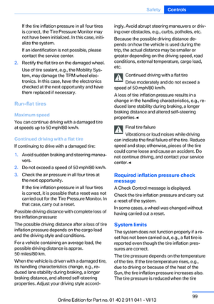 99
99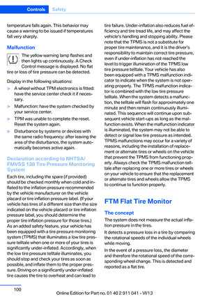 100
100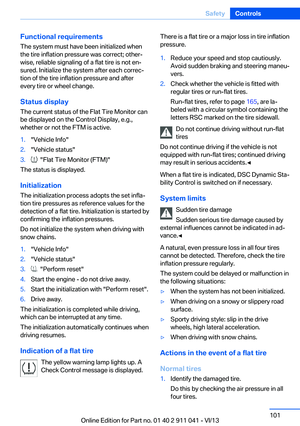 101
101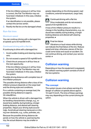 102
102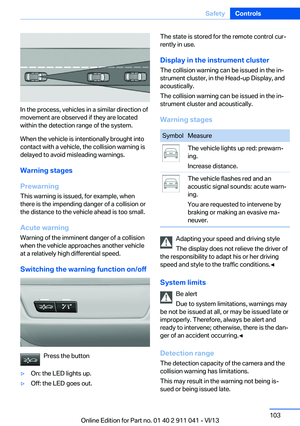 103
103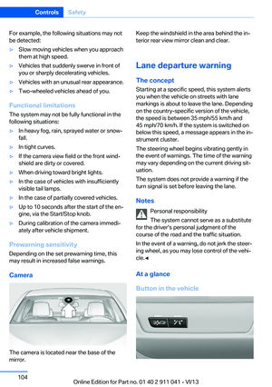 104
104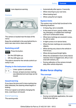 105
105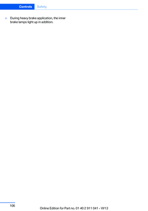 106
106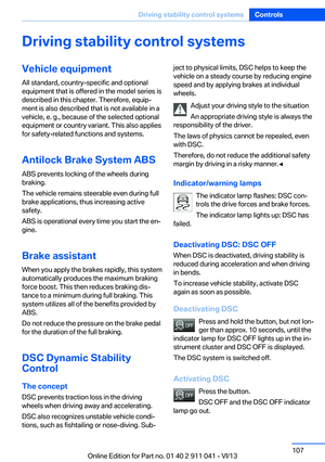 107
107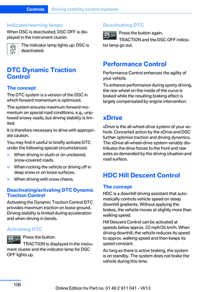 108
108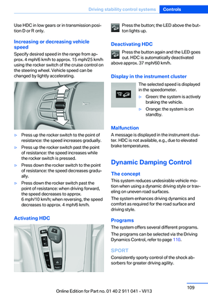 109
109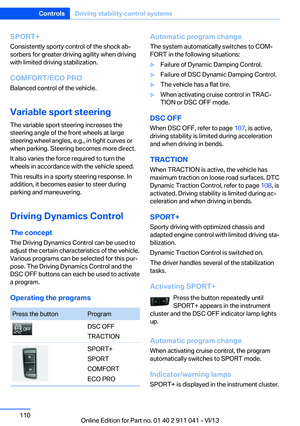 110
110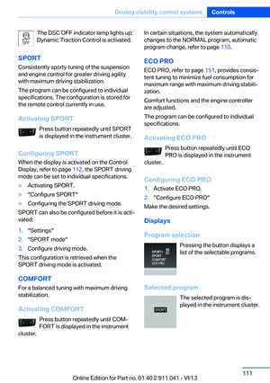 111
111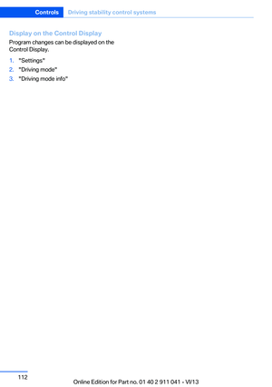 112
112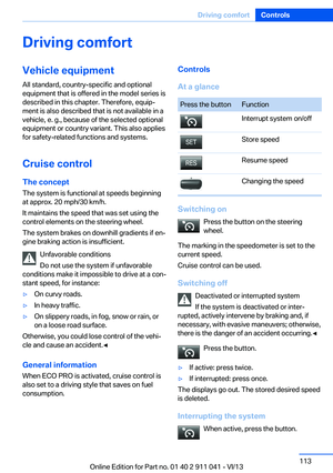 113
113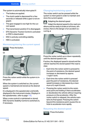 114
114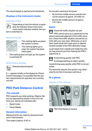 115
115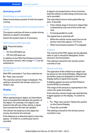 116
116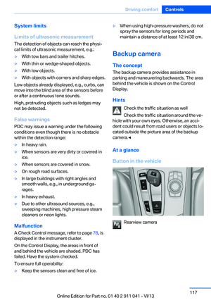 117
117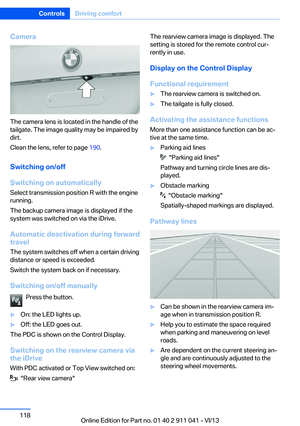 118
118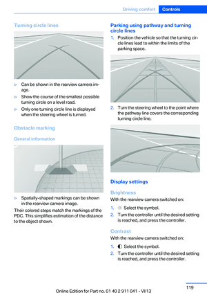 119
119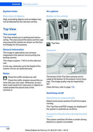 120
120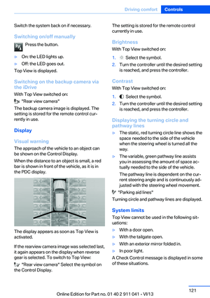 121
121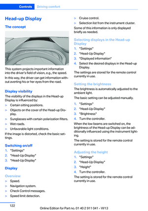 122
122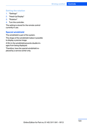 123
123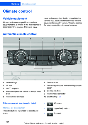 124
124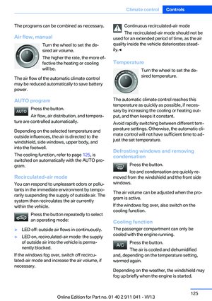 125
125 126
126 127
127 128
128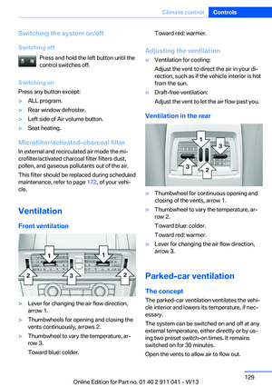 129
129 130
130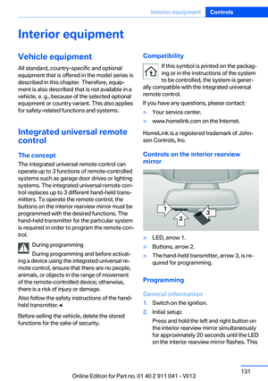 131
131 132
132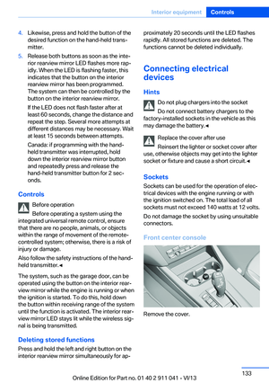 133
133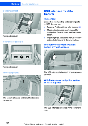 134
134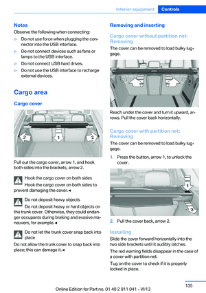 135
135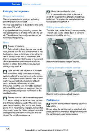 136
136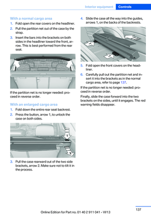 137
137 138
138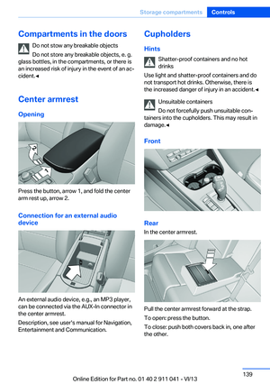 139
139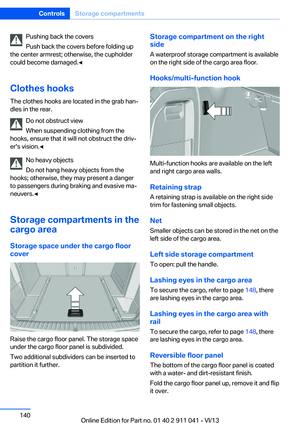 140
140 141
141 142
142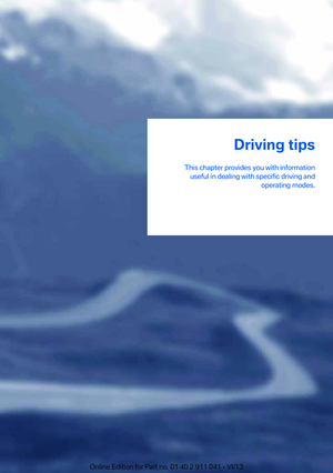 143
143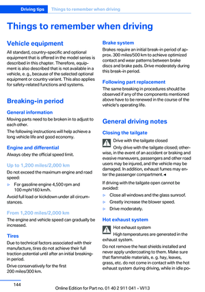 144
144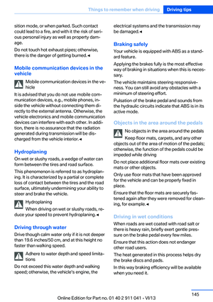 145
145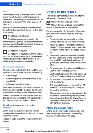 146
146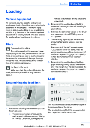 147
147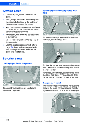 148
148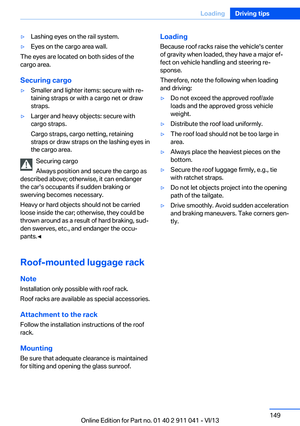 149
149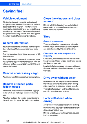 150
150 151
151 152
152 153
153 154
154 155
155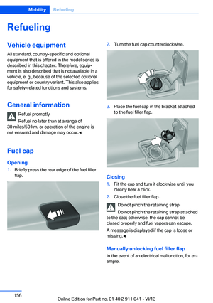 156
156 157
157 158
158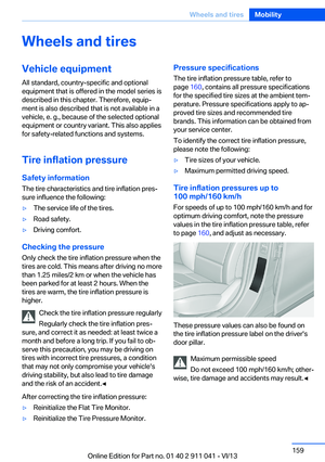 159
159 160
160 161
161 162
162 163
163 164
164 165
165 166
166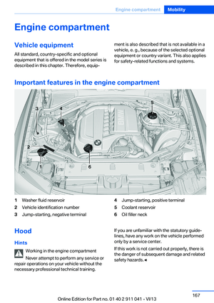 167
167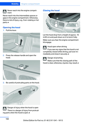 168
168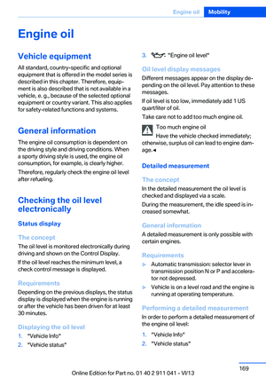 169
169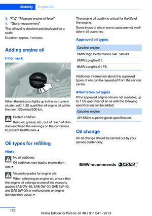 170
170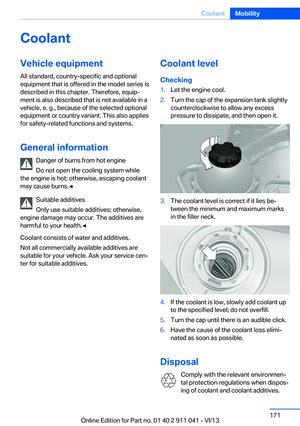 171
171 172
172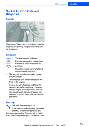 173
173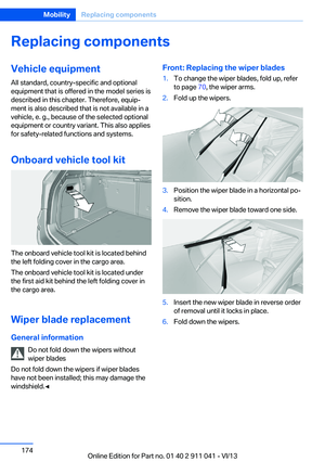 174
174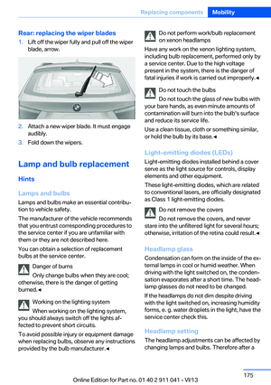 175
175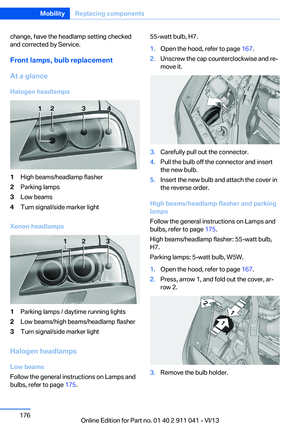 176
176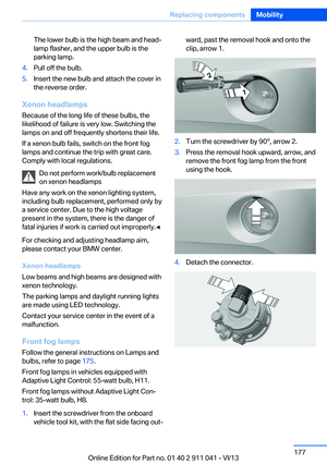 177
177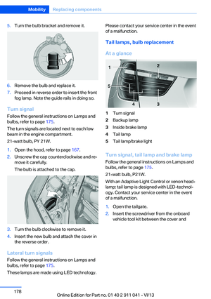 178
178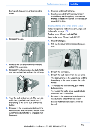 179
179 180
180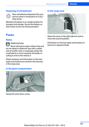 181
181 182
182 183
183 184
184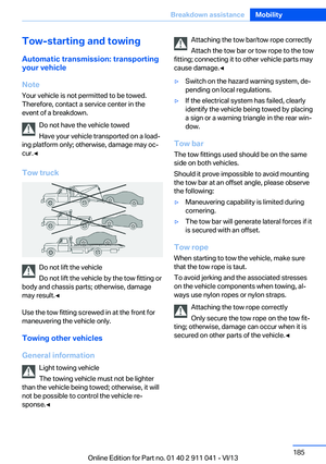 185
185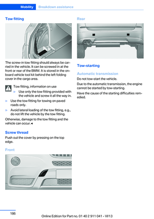 186
186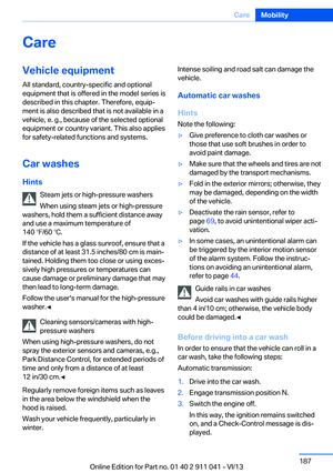 187
187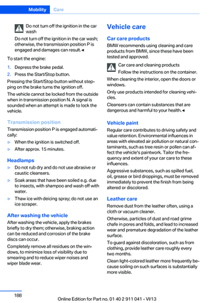 188
188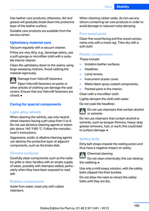 189
189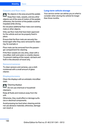 190
190 191
191 192
192 193
193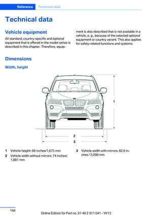 194
194 195
195 196
196 197
197 198
198 199
199 200
200 201
201 202
202 203
203 204
204 205
205 206
206 207
207
