2014 BMW X3 XDRIVE 35I center console
[x] Cancel search: center consolePage 14 of 208

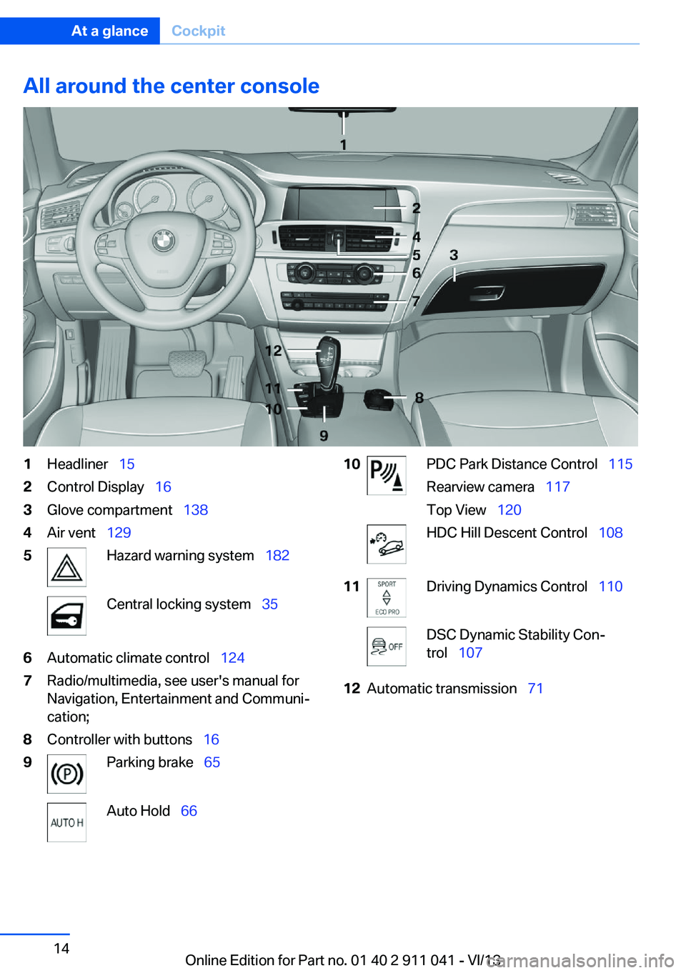
All around the center console1Headliner 152Control Display 163Glove compartment 1384Air vent 1295Hazard warning system 182Central locking system 356Automatic climate control 1247Radio/multimedia, see user's manual for
Navigation, Entertainment and Communi‐
cation;8Controller with buttons 169Parking brake 65Auto Hold 6610PDC Park Distance Control 115
Rearview camera 117
Top View 120HDC Hill Descent Control 10811Driving Dynamics Control 110DSC Dynamic Stability Con‐
trol 10712Automatic transmission 71Seite 14At a glanceCockpit14
Online Edition for Part no. 01 40 2 911 041 - VI/13
Page 133 of 208

4.Likewise, press and hold the button of the
desired function on the hand-held trans‐
mitter.5.Release both buttons as soon as the inte‐
rior rearview mirror LED flashes more rap‐
idly. When the LED is flashing faster, this
indicates that the button on the interior
rearview mirror has been programmed.
The system can then be controlled by the
button on the interior rearview mirror.
If the LED does not flash faster after at
least 60 seconds, change the distance and
repeat the step. Several more attempts at
different distances may be necessary. Wait
at least 15 seconds between attempts.
Canada: if programming with the hand-
held transmitter was interrupted, hold
down the interior rearview mirror button
and repeatedly press and release the
hand-held transmitter button for 2 sec‐
onds.
Controls
Before operation
Before operating a system using the
integrated universal remote control, ensure
that there are no people, animals, or objects
within the range of movement of the remote- controlled system; otherwise, there is a risk of
injury or damage.
Also follow the safety instructions of the hand-
held transmitter.◀
The system, such as the garage door, can be
operated using the button on the interior rear‐
view mirror while the engine is running or when
the ignition is started. To do this, hold down
the button within receiving range of the system
until the function is activated. The interior rear‐ view mirror LED stays lit while the wireless sig‐
nal is being transmitted.
Deleting stored functions Press and hold the left and right button on the
interior rearview mirror simultaneously for ap‐
proximately 20 seconds until the LED flashes
rapidly. All stored functions are deleted. The
functions cannot be deleted individually.
Connecting electrical
devices
Hints Do not plug chargers into the socket
Do not connect battery chargers to the
factory-installed sockets in the vehicle as this
may damage the battery.◀
Replace the cover after use
Reinsert the lighter or socket cover after
use, otherwise objects may get into the lighter
socket or fixture and cause a short circuit.◀
Sockets
Sockets can be used for the operation of elec‐
trical devices with the engine running or with
the ignition switched on. The total load of all
sockets must not exceed 140 watts at 12 volts.
Do not damage the socket by using unsuitable
connectors.
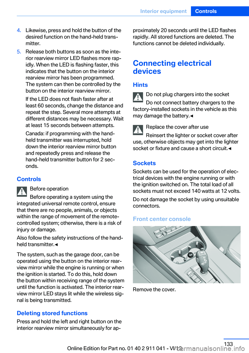
Front center console
Remove the cover.
Seite 133Interior equipmentControls133
Online Edition for Part no. 01 40 2 911 041 - VI/13
Page 134 of 208

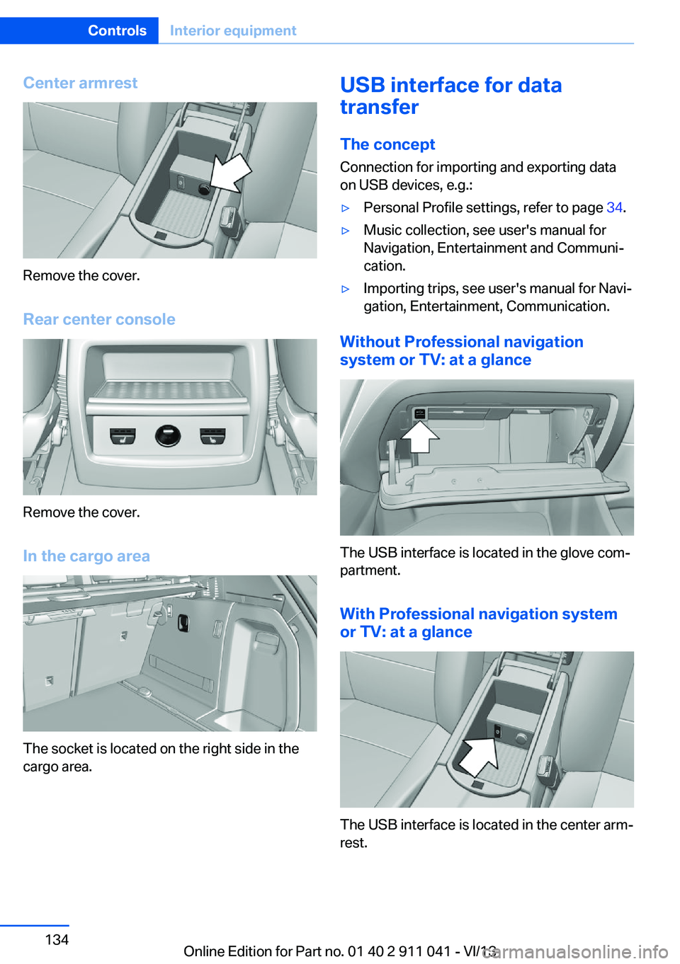
Center armrest
Remove the cover.
Rear center console
Remove the cover.
In the cargo area
The socket is located on the right side in the
cargo area.
USB interface for data
transfer
The concept Connection for importing and exporting data
on USB devices, e.g.:▷Personal Profile settings, refer to page 34.▷Music collection, see user's manual for
Navigation, Entertainment and Communi‐
cation.▷Importing trips, see user's manual for Navi‐
gation, Entertainment, Communication.
Without Professional navigation
system or TV: at a glance
The USB interface is located in the glove com‐
partment.
With Professional navigation system
or TV: at a glance
The USB interface is located in the center arm‐
rest.
Seite 134ControlsInterior equipment134
Online Edition for Part no. 01 40 2 911 041 - VI/13
Page 182 of 208

Breakdown assistanceVehicle equipment
All standard, country-specific and optional
equipment that is offered in the model series is
described in this chapter. Therefore, equip‐
ment is also described that is not available in a
vehicle, e. g., because of the selected optional
equipment or country variant. This also applies
for safety-related functions and systems.
Hazard warning flashers
The button is located in the center console.
Intelligent Emergency
Request
Requirements
▷The radio ready state is switched on.▷The Assist system is functional.▷The SIM card integrated in the vehicle has
been activated.▷A ConnectedDrive contract is available.
General information
Only press the SOS button in an emergency.
Hints
Emergency Request not guaranteed
For technical reasons, the Emergency
Request cannot be guaranteed under unfavor‐
able conditions.◀
Initiating an Emergency Request1.Press the cover briefly to open it.2.Press the SOS button until the LED in the
button lights up.▷The LED lights up: an Emergency Request
was initiated.
If the situation allows, wait in your vehicle
until the voice connection has been estab‐
lished.▷The LED flashes when a connection to the
BMW Response Center has been estab‐
lished.
When the emergency request is received
at the BMW Response Center, the BMW
Response Center contacts you and takes
further steps to help you.
Even if you are unable to respond, the
BMW Response Center can take further
steps to help you under certain circum‐
stances.
For this purpose, data that are used to de‐
termine the necessary rescue measures,
such as the current position of the vehicleSeite 182MobilityBreakdown assistance182
Online Edition for Part no. 01 40 2 911 041 - VI/13
Page 199 of 208

Brake pads, breaking in 144
Braking, hints 145
Breakdown assis‐ tance 182, 183
Breaking in 144
Brightness of Control Dis‐ play 88
Bulb replacement 175
Bulb replacement, front 176
Bulb replacement, rear 178
Bulbs and lamps 175
Button, Start/Stop 61
Bypassing, refer to Jump- starting 183
C
California Proposition 65 Warning 7
Camera, care 190
Camera, rearview cam‐ era 118
Camera, Top View 120
Can holder, refer to Cu‐ pholder 139
Car battery 180
Car care products 188
Care, displays 190
Care, vehicle 188
Cargo 147
Cargo area 135
Cargo area, enlarging 136
Cargo area lid 38
Cargo area, storage compart‐ ments 140
Cargo cover 135
Cargo, securing 148
Cargo straps, securing cargo 148
Car key, refer to Remote con‐ trol 32
Carpet, care 190
Car wash 187
Catalytic converter, refer to Hot exhaust system 144 CBS Condition Based Serv‐
ice 172
CD/Multimedia, see user's manual for Navigation, En‐
tertainment and Communi‐
cation
Center armrest 139
Center console 14
Center-Lock, see button for central locking 35
Central locking system 35
Central screen, refer to Con‐ trol Display 16
Changes, technical, refer to Safety 7
Changing parts 174
Changing wheels 180
Changing wheels/tires 164
Check Control 78
Checking the oil level elec‐ tronically 169
Children, seating position 57
Children, transporting safely 57
Child restraint fixing sys‐ tem 57
Child restraint fixing system LATCH 58
Child restraint fixing systems, mounting 57
Child safety locks 60
Child seat, mounting 57
Child seats 57
Chrome parts, care 189
Cleaning, displays 190
Climate control 124, 126
Clock 81
Closing/opening from in‐ side 38
Closing/opening via door lock 37
Closing/opening with remote control 35
Clothes hooks 140
Cockpit 12
Collision warning 102 Combination switch, refer to
Turn signals 67
Combination switch, refer to Wiper system 68
Comfort Access 41
COMFORT program, Dy‐ namic Driving Control 111
Compartments in the doors 139
Computer 85
Condensation on win‐ dows 125, 128
Condensation under the vehi‐ cle 146
Condition Based Service CBS 172
Confirmation signal 42
ConnectedDrive, see user's manual for Navigation, En‐
tertainment and Communi‐
cation
ConnectedDrive Services
Connecting electrical devi‐ ces 133
Control Display 16
Control Display, settings 87
Controller 16, 17
Control systems, driving sta‐ bility 107
Convenient opening 36
Coolant 171
Coolant temperature 80
Cooling function 125, 128
Cooling, maximum 127
Cooling system 171
Corrosion on brake discs 146
Cruise control 113
Cruising range 81
Cupholder 139
Current fuel consumption 81
D
Damage, tires 163
Damping control, dy‐ namic 109 Seite 199Everything from A to ZReference199
Online Edition for Part no. 01 40 2 911 041 - VI/13