2014 BMW I8 tow
[x] Cancel search: towPage 155 of 216

Load
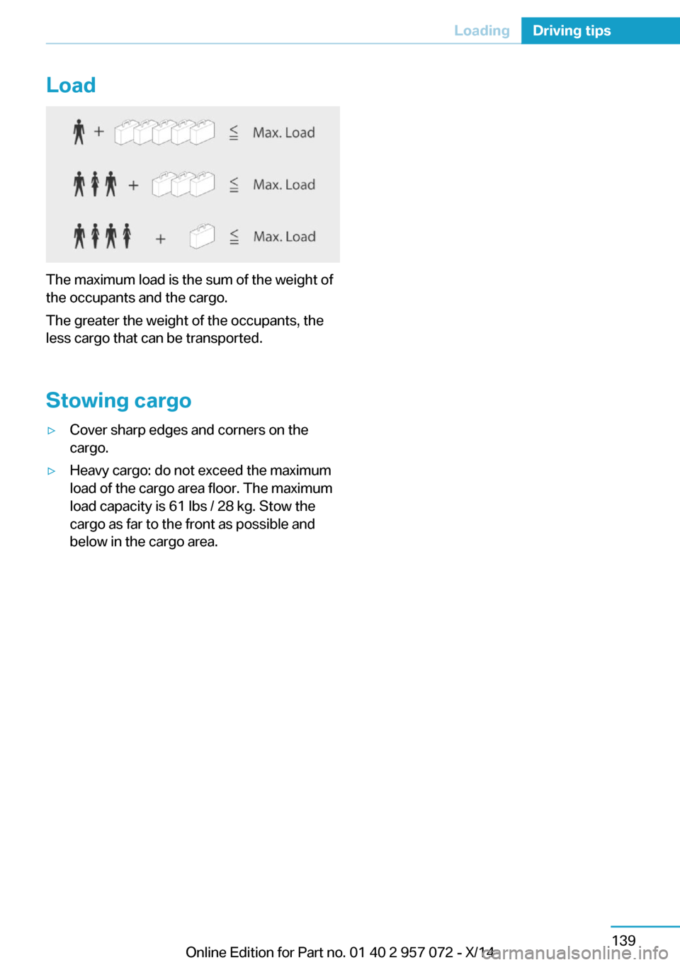
The maximum load is the sum of the weight of
the occupants and the cargo.
The greater the weight of the occupants, the
less cargo that can be transported.
Stowing cargo
▷Cover sharp edges and corners on the
cargo.▷Heavy cargo: do not exceed the maximum
load of the cargo area floor. The maximum
load capacity is 61 lbs / 28 kg. Stow the
cargo as far to the front as possible and
below in the cargo area.Seite 139LoadingDriving tips139
Online Edition for Part no. 01 40 2 957 072 - X/14
Page 165 of 216

3.Remove the charging cable from the
charging port, arrow 2.4.Close the charging port flap.5.Attach cover of the charging cable plug if
needed.6.Disconnect either a Level 1 or Level 2
charging cable from the household socket
or the port on the charging station.7.Stow the charging cable.
At a charging station, insert the perma‐
nently installed charging cable in the place
provided for it.
Manual release
The charging cable may be locked during the
charging process.
The charging cable may be locked during the
charging process if the vehicle is locked.
Manual unlocking of the charging
cable
In case of an electrical malfunction, the charg‐
ing cable can be manually unlocked.
When charging at a charging station, complete
the charging process at the charging station
before unlocking the charging cable.
1.Open door on the side of the charging port
flap.2.Open cover, arrow 1.
Pull the blue knob, Arrow 2. Charging
cable is manually unlocked.
3.Grasp the charging cable at the gripping
areas.4.Remove charging cable.
Charging operation
Hints Following safety instructions of the
power mains connection
During the charging process, heed the safety
instructions of the respective power mains
connection. Otherwise, there could be a risk of
personal injury or property damage from high
voltage, e.g., from electrocution or fire.◀
Using a Level 1 charging cable at other
household sockets
Before charging at other household sockets,
adapt the charging current strength to the
mains. Otherwise, there is a risk of fire, e.g.,
from overheating of the household socket or
overloading of the power mains.◀
Starting charging process
1.Engage selector lever position P. Set the
parking brake if needed.2.Planning charging process, refer to
page 150.3.Switch off drive readiness.4.Connect either a Level 1 or Level 2 charg‐
ing cable to the household socket or the
port on the charging station.5.Open charging port flap.6.Connect charging cable to the vehicle, re‐
fer to page 148.
At high temperatures, initially the high-voltage
battery is cooled. The charging process can be
started with a delay.
Display of the charging status
The charging status is indicated by the indica‐
tor light at the charging port.
Seite 149Charging vehicleMobility149
Online Edition for Part no. 01 40 2 957 072 - X/14
Page 167 of 216

Settings are stored. When you change charg‐
ing locations you also might need to change
the setting for charging.
Set the charge current strength at other
household sockets to "Low".
Stopping charging process The charging operation can be stopped at any
time by removing the charging cable and con‐
tinued at a later time by connecting the charg‐
ing cable in order to use other loads on the
power connection or to prevent simultaneous
high power from multiple loads.
The charging operation is interrupted when the
vehicle is unlocked and automatically resumed
after a brief time or when it is locked.
Continue charging operation If the charging operation is interrupted, e.g.,
through a temporary power failure, the charg‐
ing operation is automatically continued after
the interruption.
Terminating charging process1.Removing the charging cable from the ve‐
hicle, refer to page 148.2.Stow the charging cable as required.3.Close the charging port flap.4.Lock vehicle if it is unlocked.
Displays in the instrument
cluster
The charging state indicator light shows the
charging state of the high-voltage battery in
the instrument cluster, if operating readiness is
turned on. If all segments are filled, the high-
voltage battery is fully charged.
Even if no segments are filled, the high-voltage
system is still under high voltage.
DisplayMeaningPlug blue: charging operation active.
White plug: charging interruption.End of charging time or set depar‐
ture time.Charging progress bar.Indicator in blue: charged electrical
range.Indicator in white: maximum electri‐
cal range.Departure time set.Climate control activated at depar‐
ture time.Flashing: ventilation active.Flashing: heating active.Flashing: cooling active.
Departure time
The concept For optimum range and climate control, the
departure time can be set before parking the
car.
With a set departure time, the vehicle is cli‐
mate controlled during the charging process
when climate control is set. Climate control
output is reduced during the trip. This in‐
creases the range during electric driving.
Seite 151Charging vehicleMobility151
Online Edition for Part no. 01 40 2 957 072 - X/14
Page 178 of 216

A represent higher levels of performance on
the laboratory test wheel than the minimum re‐
quired by law.
Temperature grade for this tire
The temperature grade for this tire is es‐
tablished for a tire that is properly inflated and
not overloaded. Excessive speed, underinfla‐
tion, or excessive loading, either separately or
in combination, can cause heat buildup and
possible tire failure.
If necessary, have the vehicle towed.◀
M+S
Winter and all-season tires with better cold
weather performance than summer tires.
Tire tread Summer tires Do not drive with a tire tread depth of less than
0.12 in/3 mm.
There is an increased danger of hydroplaning if
the tire tread depth is less than 0.12 in/3 mm.
Winter tires
Do not drive with a tire tread depth of less than
0.16 in/4 mm.
Below a tread depth of 0.16 in/4 mm, tires are
less suitable for winter operation.Minimum tread depth
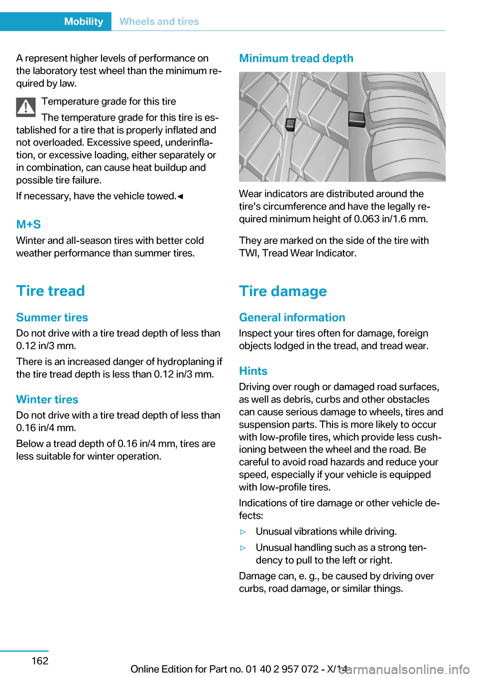
Wear indicators are distributed around the
tire's circumference and have the legally re‐
quired minimum height of 0.063 in/1.6 mm.
They are marked on the side of the tire with
TWI, Tread Wear Indicator.
Tire damage
General information
Inspect your tires often for damage, foreign
objects lodged in the tread, and tread wear.
Hints
Driving over rough or damaged road surfaces,
as well as debris, curbs and other obstacles
can cause serious damage to wheels, tires and
suspension parts. This is more likely to occur
with low-profile tires, which provide less cush‐
ioning between the wheel and the road. Be
careful to avoid road hazards and reduce your
speed, especially if your vehicle is equipped
with low-profile tires.
Indications of tire damage or other vehicle de‐
fects:
▷Unusual vibrations while driving.▷Unusual handling such as a strong ten‐
dency to pull to the left or right.
Damage can, e. g., be caused by driving over
curbs, road damage, or similar things.
Seite 162MobilityWheels and tires162
Online Edition for Part no. 01 40 2 957 072 - X/14
Page 179 of 216

In case of tire damage
If there are indications of tire damage, re‐
duce your speed immediately and have the
rims and tires checked right away; otherwise,
there is the increased risk of an accident.
Drive carefully to the nearest service center.
Have the vehicle towed or transported there.
Otherwise, tire damage can become life threat‐
ening for vehicle occupants and also other traf‐
fic.◀
Repair of tire damage
For safety reasons, the manufacturer of
your vehicle recommends that you do not have
damaged tires repaired; they should be re‐
placed. Otherwise, damage can occur as a re‐
sult.◀
Changing wheels and tires
Mounting Information on mounting tires
Have mounting and balancing performed
only by a service center.
If work is not carried out properly, there is a
danger of subsequent damage and related
safety hazards.◀
Wheel and tire combination
You can ask the service center about the right
wheel/tire combination and wheel rim versions
for the vehicle.
Incorrect wheel and tire combinations impair
the function of a variety of systems such as
ABS or DSC.
To maintain good handling and vehicle re‐
sponse, use only tires with a single tread con‐
figuration from a single manufacturer.
Following tire damage, have the original wheel
and tire combination remounted on the vehicle
as soon as possible.Approved wheels and tires
You should only use wheels and tires
that have been approved by the vehicle manu‐
facturer for your vehicle type; otherwise, e.g.,
despite having the same official size ratings,
variations can lead to chassis contact and with
it, the risk of severe accidents
The manufacturer of your vehicle cannot eval‐
uate non-approved wheels and tires to deter‐
mine if they are suited for use, and therefore
cannot guarantee the operating safety of the
vehicle.◀
Recommended tire brands
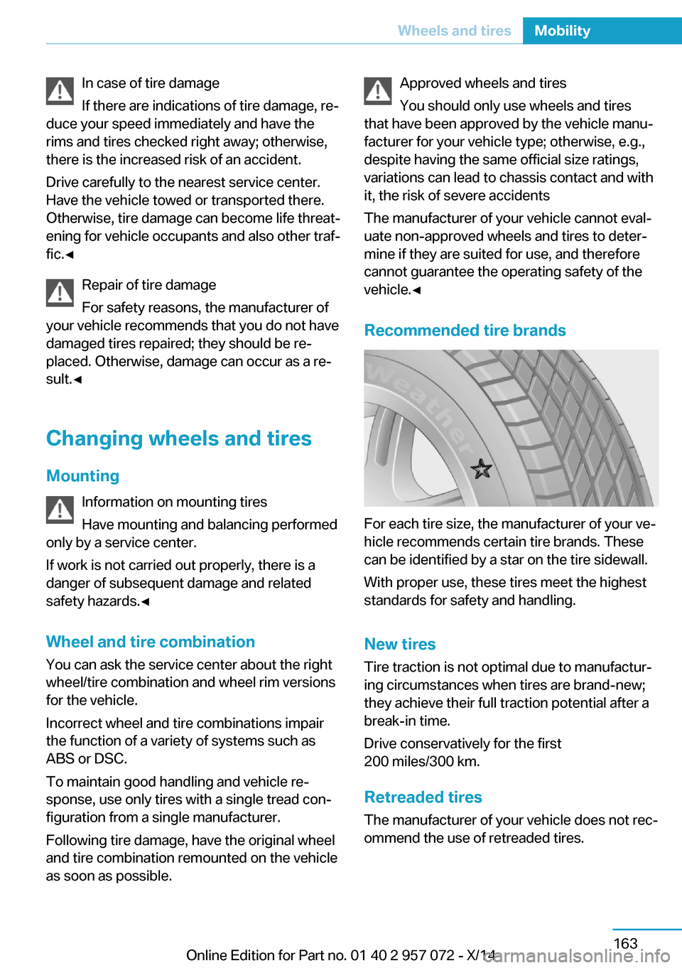
For each tire size, the manufacturer of your ve‐
hicle recommends certain tire brands. These
can be identified by a star on the tire sidewall.
With proper use, these tires meet the highest
standards for safety and handling.
New tires Tire traction is not optimal due to manufactur‐
ing circumstances when tires are brand-new;
they achieve their full traction potential after a
break-in time.
Drive conservatively for the first
200 miles/300 km.
Retreaded tires
The manufacturer of your vehicle does not rec‐
ommend the use of retreaded tires.
Seite 163Wheels and tiresMobility163
Online Edition for Part no. 01 40 2 957 072 - X/14
Page 188 of 216

Replacing componentsVehicle features and optionsThis chapter describes all standard, country-
specific and optional features offered with the
series. It also describes features that are not
necessarily available in your car, e. g., due to
the selected options or country versions. This
also applies to safety-related functions and
systems.
Wiper blade replacement
General information Do not fold down the wipers without
wiper blades
Do not fold down the wipers if wiper blades
have not been installed; this may damage the
windshield.◀
Replacing the wiper blades1.To change the wiper blades, fold up, refer
to page 66, the wiper arms.2.Fold up the wipers.3.Position the wiper blade in a horizontal po‐
sition.4.Remove the wiper blade toward one side.5.Insert the new wiper blade in reverse order
of removal until it locks in place.6.Fold down the wipers.
Lamp and bulb replacement
General information
All headlights and lights are made using LED
or laser technology. Contact your service cen‐
ter in the event of a malfunction.
Headlight glass
Condensation can form on the inside of the ex‐
ternal lights in cool or humid weather. When
driving with the light switched on, the conden‐
sation evaporates after a short time. The head‐
light glass does not need to be changed.
If the headlights do not dim despite driving
with the light switched on, increasing humidity
forms, e. g. water droplets in the light, have the
service center check this.
Light-emitting diodes (LEDs)
Some items of equipment use light-emitting
diodes installed behind a cover as a light
source.
These light-emitting diodes, which are related
to conventional lasers, are officially designated
as Class 1 light-emitting diodes.
Seite 172MobilityReplacing components172
Online Edition for Part no. 01 40 2 957 072 - X/14
Page 193 of 216

Tow-starting and towingTransporting your vehicle
Note
Your vehicle is not permitted to be towed.
Therefore, contact a service center in the
event of a breakdown.
Do not have the vehicle towed
Have your vehicle transported on a load‐
ing platform only; otherwise, damage may oc‐
cur.◀
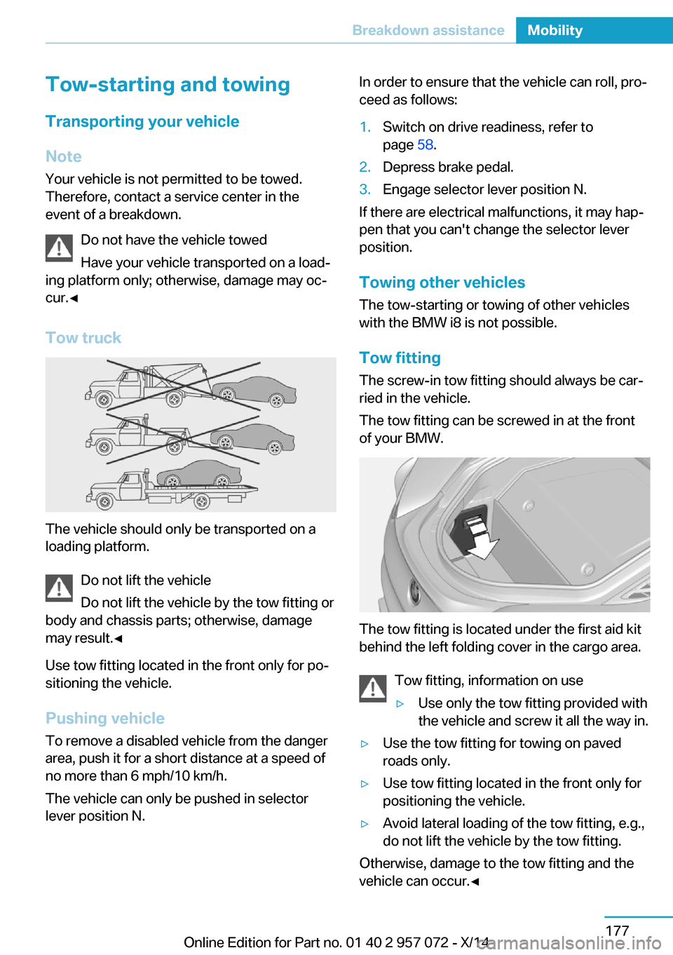
Tow truck
The vehicle should only be transported on a
loading platform.
Do not lift the vehicle
Do not lift the vehicle by the tow fitting or
body and chassis parts; otherwise, damage
may result.◀
Use tow fitting located in the front only for po‐
sitioning the vehicle.
Pushing vehicle To remove a disabled vehicle from the danger
area, push it for a short distance at a speed of
no more than 6 mph/10 km/h.
The vehicle can only be pushed in selector
lever position N.
In order to ensure that the vehicle can roll, pro‐
ceed as follows:1.Switch on drive readiness, refer to
page 58.2.Depress brake pedal.3.Engage selector lever position N.
If there are electrical malfunctions, it may hap‐
pen that you can't change the selector lever
position.
Towing other vehicles The tow-starting or towing of other vehicles
with the BMW i8 is not possible.
Tow fitting The screw-in tow fitting should always be car‐
ried in the vehicle.
The tow fitting can be screwed in at the front
of your BMW.
The tow fitting is located under the first aid kit
behind the left folding cover in the cargo area.
Tow fitting, information on use
▷Use only the tow fitting provided with
the vehicle and screw it all the way in.▷Use the tow fitting for towing on paved
roads only.▷Use tow fitting located in the front only for
positioning the vehicle.▷Avoid lateral loading of the tow fitting, e.g.,
do not lift the vehicle by the tow fitting.
Otherwise, damage to the tow fitting and the
vehicle can occur.◀
Seite 177Breakdown assistanceMobility177
Online Edition for Part no. 01 40 2 957 072 - X/14
Page 194 of 216

Screw thread for tow fitting
Press on the mark on the edge of the cover to
push it out.
Tow-starting
Steptronic transmission
Do not tow-start the vehicle.
Tow-starting the engine is not possible due to
the Steptronic transmission.
Have the cause of the starting problems fixed.
Safety of the high-voltage
system
Working on the vehicle Maintenance and repairs
Have maintenance and repair work per‐
formed only by a service center or a workshop
that works according to BMW specifications
with appropriately trained personnel. Other‐
wise, there is the risk of fatal injury from elec‐
trocution due to the high-voltage system's
high voltage.◀
Body work and working on the high-volt‐
age system
Do not perform any modifications or work on
the vehicle, especially maintenance and repair
work on the high-voltage system and the car‐
bon body and avoid retrofitting accessories.
If work is not carried out properly, there is the
risk of fire and fatal injury from electrocution
due to the high-voltage system's high voltage.
Modifications and work on the vehicle may
only be carried out by an authorized BMW i
service center or one that operates according
to BMW i specifications with personnel trained
accordingly.◀
Your vehicle's high-voltage system is a self-
contained system. Safety is ensured as long as
no work is performed on technical components
or on the chassis.
High-voltage system: contact with
water
The high-voltage system is typically safe even
in the following example situations:▷Water in the footwell, for instance after a
rainstorm when sunroof was kept open.▷Vehicle is in water but only up to the al‐
lowed height.▷Liquid eslides in the cargo area.
In these cases there is no risk of injury from
electrocution. Other damage to the vehicle is
possible.
High-voltage system: automatic
deactivation
If an accident occurs, the high-voltage system
is switched off automatically to prevent risk of
danger to occupants and other traffic.
Read the information on What to do after an
accident, refer to page 178.
What to do after an accident Hints After an accident
After an accident, do not touch any high-
voltage components such as orange colored
high-voltage cables or parts that are in contact
with exposed high-voltage cables. Otherwise,
Seite 178MobilityBreakdown assistance178
Online Edition for Part no. 01 40 2 957 072 - X/14