2014 BMW 5 SERIES GRAN TURISMO check engine
[x] Cancel search: check enginePage 39 of 259

Replacing the battery1.Remove integrated key from remote con‐
trol.2.Push in the catch with the key, arrow 1.3.Remove the cover of the battery compart‐
ment, arrow 2.4.Insert a battery of the same type with the
positive side facing up.5.Press the cover closed.
Take the used battery to a recycling
center or to your service center.
New remote controls New remote controls are available from the
service center.
Loss of the remote controls Lost remote controls can be disabled by your
service center.
Emergency detection of remote
control
It is possible to reel on the ignition or start the
engine in situations such as the following:
▷Interference of radio transmission to re‐
mote control by external sources e.g., by
radio masts.▷Empty battery in remote control.▷Interference from radio transmissions
through mobile devices in close proximity
to remote control.▷Interference of radio transmission by
charger while charging items such as mo‐
bile devices in the vehicle.
A Check Control message is displayed if an at‐
tempt is made to reel on the ignition or start
the engine.
Starting the engine with emergency
detection of the remote control
If a respective Check Control message ap‐
pears, hold the remote control with its back
against the marked area on the steering col‐
umn. The BMW logo on the remote control
should be at the same height as the marked
area. Press the Start/Stop button within
10 seconds while pressing the brake pedal.
If the remote control is not recognized: slightly
change the height position of the remote con‐
trol and repeat the procedure.
Personal Profile
The concept Individual settings in the vehicle are saved in
personal profiles. Every remote control is as‐
signed the last active profile.
Three personal profiles and a guest profile can
be created.
▷Changes to the settings are automatically
saved in the profile currently activated.▷Unlocking the car activates the profile that
is stored in the remote control.Seite 35Opening and closingControls35
Online Edition for Part no. 01 40 2 956 191 - X/14
Page 56 of 259
Opening/closing the glass sunroof and
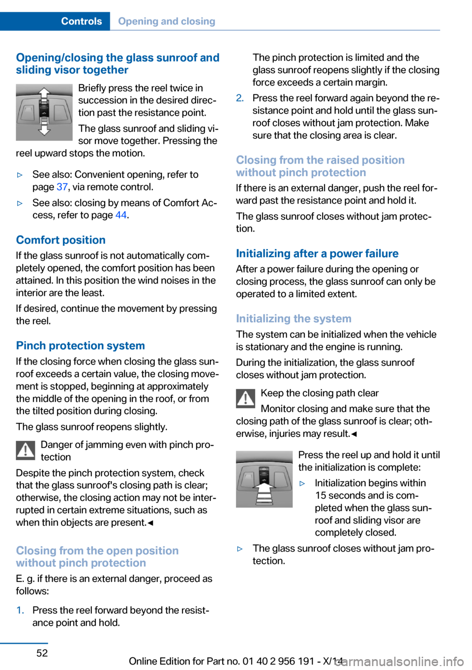
sliding visor together
Briefly press the reel twice in
succession in the desired direc‐
tion past the resistance point.
The glass sunroof and sliding vi‐
sor move together. Pressing the
reel upward stops the motion.▷See also: Convenient opening, refer to
page 37, via remote control.▷See also: closing by means of Comfort Ac‐
cess, refer to page 44.
Comfort position
If the glass sunroof is not automatically com‐
pletely opened, the comfort position has been
attained. In this position the wind noises in the
interior are the least.
If desired, continue the movement by pressing
the reel.
Pinch protection system
If the closing force when closing the glass sun‐
roof exceeds a certain value, the closing move‐
ment is stopped, beginning at approximately
the middle of the opening in the roof, or from
the tilted position during closing.
The glass sunroof reopens slightly.
Danger of jamming even with pinch pro‐
tection
Despite the pinch protection system, check
that the glass sunroof's closing path is clear;
otherwise, the closing action may not be inter‐
rupted in certain extreme situations, such as
when thin objects are present.◀
Closing from the open position
without pinch protection
E. g. if there is an external danger, proceed as
follows:
1.Press the reel forward beyond the resist‐
ance point and hold.The pinch protection is limited and the
glass sunroof reopens slightly if the closing
force exceeds a certain margin.2.Press the reel forward again beyond the re‐
sistance point and hold until the glass sun‐
roof closes without jam protection. Make
sure that the closing area is clear.
Closing from the raised position
without pinch protection
If there is an external danger, push the reel for‐
ward past the resistance point and hold it.
The glass sunroof closes without jam protec‐
tion.
Initializing after a power failure After a power failure during the opening or
closing process, the glass sunroof can only be
operated to a limited extent.
Initializing the system
The system can be initialized when the vehicle
is stationary and the engine is running.
During the initialization, the glass sunroof
closes without jam protection.
Keep the closing path clear
Monitor closing and make sure that the
closing path of the glass sunroof is clear; oth‐
erwise, injuries may result.◀
Press the reel up and hold it until
the initialization is complete:
▷Initialization begins within
15 seconds and is com‐
pleted when the glass sun‐
roof and sliding visor are
completely closed.▷The glass sunroof closes without jam pro‐
tection.Seite 52ControlsOpening and closing52
Online Edition for Part no. 01 40 2 956 191 - X/14
Page 77 of 259
The engine can only be started via the Start/
Stop button.
Note Even if driving off was not intended, the deacti‐
vated engine starts up automatically in the fol‐
lowing situations:▷Excessive warming of the car's interior
when the cooling function is switched on.▷The steering wheel is turned.▷Steptronic transmission: change from se‐
lector lever position D to R, N or M/S.▷Steptronic transmission: change from se‐
lector lever position P to N, D, R or M/S.▷Fogging of the windows when the auto‐
matic climate control is switched on.▷Vehicle battery is heavily discharged.▷Excessive cooling of the car's interior when
the heating is switched on.
Activating/deactivating the system
manually
Using the button
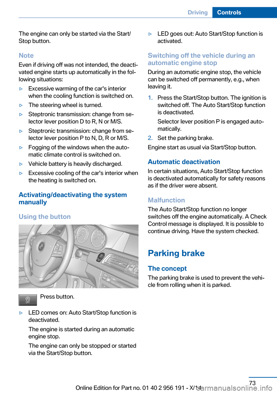
Press button.
▷LED comes on: Auto Start/Stop function is
deactivated.
The engine is started during an automatic
engine stop.
The engine can only be stopped or started
via the Start/Stop button.▷LED goes out: Auto Start/Stop function is
activated.
Switching off the vehicle during an
automatic engine stop
During an automatic engine stop, the vehicle
can be switched off permanently, e.g., when
leaving it.
1.Press the Start/Stop button. The ignition is
switched off. The Auto Start/Stop function
is deactivated.
Selector lever position P is engaged auto‐
matically.2.Set the parking brake.
Engine start as usual via Start/Stop button.
Automatic deactivation
In certain situations, Auto Start/Stop function
is deactivated automatically for safety reasons
as if the driver were absent.
Malfunction
The Auto Start/Stop function no longer
switches off the engine automatically. A Check
Control message is displayed. It is possible to
continue driving. Have the system checked.
Parking brake The concept
The parking brake is used to prevent the vehi‐
cle from rolling when it is parked.
Seite 73DrivingControls73
Online Edition for Part no. 01 40 2 956 191 - X/14
Page 78 of 259
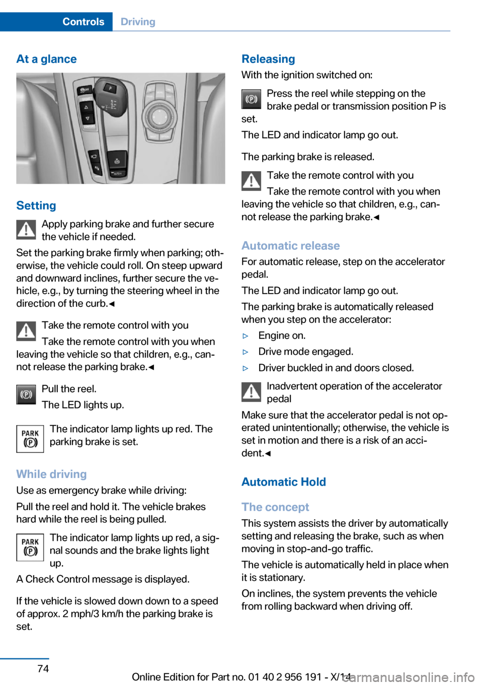
At a glance
SettingApply parking brake and further secure
the vehicle if needed.
Set the parking brake firmly when parking; oth‐
erwise, the vehicle could roll. On steep upward
and downward inclines, further secure the ve‐
hicle, e.g., by turning the steering wheel in the
direction of the curb.◀
Take the remote control with you
Take the remote control with you when
leaving the vehicle so that children, e.g., can‐
not release the parking brake.◀
Pull the reel.
The LED lights up.
The indicator lamp lights up red. The
parking brake is set.
While driving
Use as emergency brake while driving:
Pull the reel and hold it. The vehicle brakes
hard while the reel is being pulled.
The indicator lamp lights up red, a sig‐
nal sounds and the brake lights light
up.
A Check Control message is displayed.
If the vehicle is slowed down down to a speed of approx. 2 mph/3 km/h the parking brake is
set.
Releasing
With the ignition switched on:
Press the reel while stepping on the
brake pedal or transmission position P is
set.
The LED and indicator lamp go out.
The parking brake is released. Take the remote control with you
Take the remote control with you when
leaving the vehicle so that children, e.g., can‐
not release the parking brake.◀
Automatic release For automatic release, step on the accelerator
pedal.
The LED and indicator lamp go out.
The parking brake is automatically released
when you step on the accelerator:▷Engine on.▷Drive mode engaged.▷Driver buckled in and doors closed.
Inadvertent operation of the accelerator
pedal
Make sure that the accelerator pedal is not op‐
erated unintentionally; otherwise, the vehicle is
set in motion and there is a risk of an acci‐
dent.◀
Automatic Hold
The concept This system assists the driver by automatically
setting and releasing the brake, such as when
moving in stop-and-go traffic.
The vehicle is automatically held in place when
it is stationary.
On inclines, the system prevents the vehicle
from rolling backward when driving off.
Seite 74ControlsDriving74
Online Edition for Part no. 01 40 2 956 191 - X/14
Page 87 of 259
If the shift paddles on the steering wheel are
used to shift gears in automatic mode, the
transmission temporarily switches to manual
mode.
If the selector lever is still in selector lever po‐
sition D, it is possible to reel back into the au‐
tomatic mode:▷Pull and hold right shift paddle.
Or
▷In addition to the briefly pulled right shift
paddle, briefly pull the left shift paddle.
In the manual mode, if there has been no ac‐
celeration or shifting of the shift paddles within
a certain amount of time, the transmission
switches back to automatic mode.
Displays in the instrument cluster The selector lever position is dis‐played, e.g.: P.
Electronic unlocking of the
transmission lock
General information Electronically unlock the transmission lock to
maneuver vehicle from the danger area.
Unlocking is possible, if the started can spin
the engine.
Engaging selector lever position N
1.Depress the brake pedal.2.Press the Start/Stop button. The starter
must audibly start.3.Press and hold the selector lever into posi‐
tion N.
A corresponding Check Control message
is displayed.4.Press the selector lever again into posi‐
tion N within approx. 6 seconds.Position N is displayed in the instrument
cluster.5.Release brake, as soon as the starter
stops.6.Maneuver the vehicle from the danger area
and secure it against moving on its own.Seite 83DrivingControls83
Online Edition for Part no. 01 40 2 956 191 - X/14
Page 88 of 259
DisplaysVehicle features and optionsThis chapter describes all standard, country-
specific and optional features offered with the
series. It also describes features that are notnecessarily available in your car, e. g., due to
the selected options or country versions. This
also applies to safety-related functions and
systems.
Overview, instrument cluster
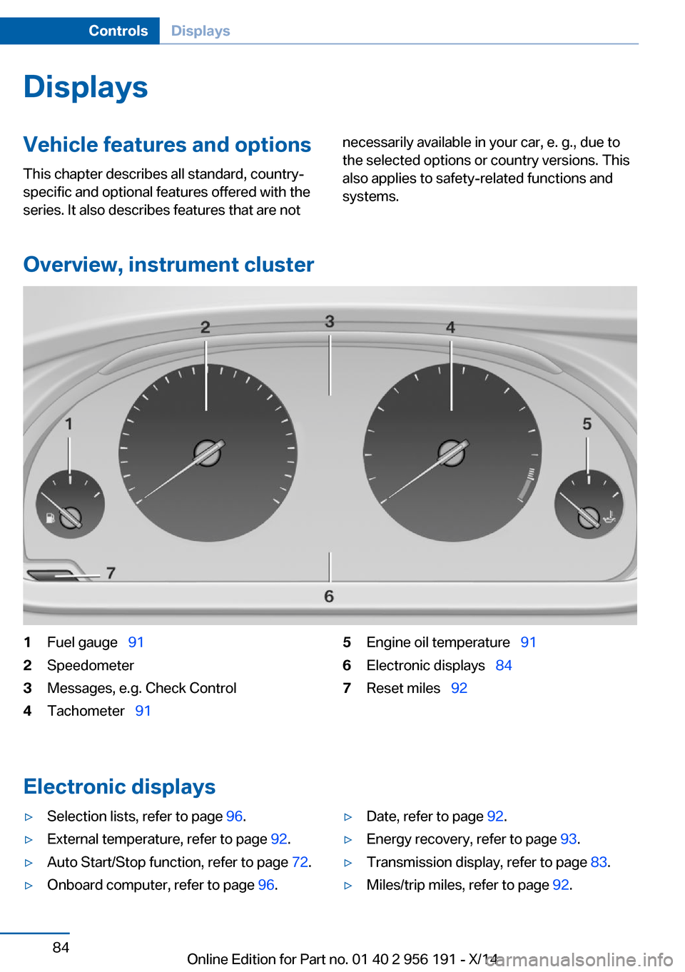
1Fuel gauge 912Speedometer3Messages, e.g. Check Control4Tachometer 915Engine oil temperature 916Electronic displays 847Reset miles 92
Electronic displays
▷Selection lists, refer to page 96.▷External temperature, refer to page 92.▷Auto Start/Stop function, refer to page 72.▷Onboard computer, refer to page 96.▷Date, refer to page 92.▷Energy recovery, refer to page 93.▷Transmission display, refer to page 83.▷Miles/trip miles, refer to page 92.Seite 84ControlsDisplays84
Online Edition for Part no. 01 40 2 956 191 - X/14
Page 89 of 259
▷Messages, e.g. Check Control, refer to
page 87.▷Current fuel consumption, refer to
page 93.▷Navigation display, see User's manual for
Navigation, Entertainment and Communi‐
cation.▷Range, refer to page 92.▷Status, Driving Dynamics Control, refer to
page 138.▷Service requirements, refer to page 93.▷Speed limit detection, refer to page 94.▷Time, refer to page 92.
Multifunctional instrument display
The concept
The instrument display is a variable display. In
the event of a program change, the display
rendition adapts to the respective program
through the Driving Dynamics Control. The
change of appearance can be deactivated on
the Control Display.Some of the displays in the instrument display
may differ from the way they are shown in this
Owner's Manual.
At a glance
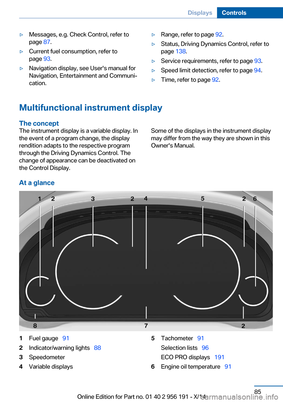
1Fuel gauge 912Indicator/warning lights 883Speedometer4Variable displays5Tachometer 91
Selection lists 96
ECO PRO displays 1916Engine oil temperature 91Seite 85DisplaysControls85
Online Edition for Part no. 01 40 2 956 191 - X/14
Page 92 of 259
In addition, an acoustic signal may sound and a
text message may appear on the Control Dis‐
play.
Indicator/warning lights
General information
The indicator and warning lights in the instru‐
ment cluster can light up in a variety of combi‐
nations and colors.
Several of the lights are checked for proper
functioning and light up temporarily when the
engine is started or the ignition is switched on.
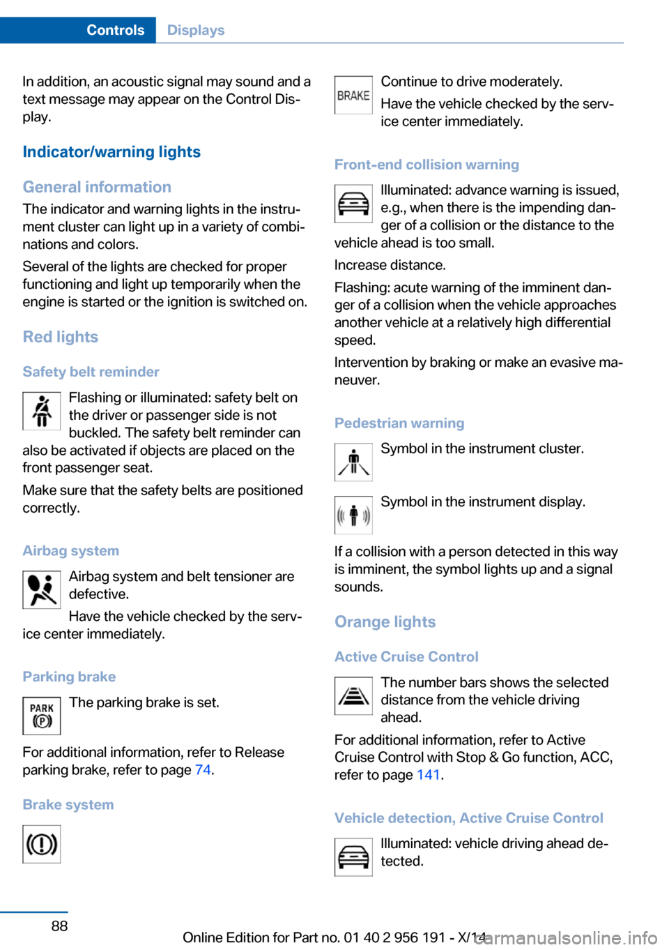
Red lights Safety belt reminder Flashing or illuminated: safety belt on
the driver or passenger side is not
buckled. The safety belt reminder can
also be activated if objects are placed on the
front passenger seat.
Make sure that the safety belts are positioned
correctly.
Airbag system Airbag system and belt tensioner are
defective.
Have the vehicle checked by the serv‐
ice center immediately.
Parking brake The parking brake is set.
For additional information, refer to Release
parking brake, refer to page 74.
Brake systemContinue to drive moderately.
Have the vehicle checked by the serv‐ ice center immediately.
Front-end collision warning Illuminated: advance warning is issued,
e.g., when there is the impending dan‐
ger of a collision or the distance to the
vehicle ahead is too small.
Increase distance.
Flashing: acute warning of the imminent dan‐
ger of a collision when the vehicle approaches
another vehicle at a relatively high differential
speed.
Intervention by braking or make an evasive ma‐
neuver.
Pedestrian warning Symbol in the instrument cluster.
Symbol in the instrument display.
If a collision with a person detected in this way
is imminent, the symbol lights up and a signal
sounds.
Orange lights Active Cruise Control The number bars shows the selected
distance from the vehicle driving
ahead.
For additional information, refer to Active
Cruise Control with Stop & Go function, ACC,
refer to page 141.
Vehicle detection, Active Cruise Control Illuminated: vehicle driving ahead de‐
tected.Seite 88ControlsDisplays88
Online Edition for Part no. 01 40 2 956 191 - X/14