2014 BMW 328I XDRIVE SPORTS WAGON warning
[x] Cancel search: warningPage 136 of 244
Cameras
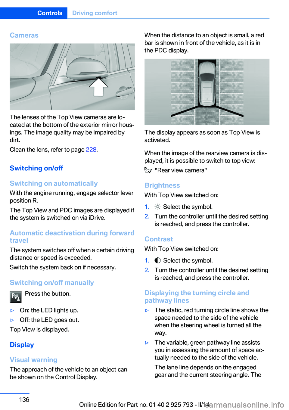
The lenses of the Top View cameras are lo‐
cated at the bottom of the exterior mirror hous‐
ings. The image quality may be impaired by
dirt.
Clean the lens, refer to page 228.
Switching on/off
Switching on automatically With the engine running, engage selector lever
position R.
The Top View and PDC images are displayed if
the system is switched on via iDrive.
Automatic deactivation during forward
travel
The system switches off when a certain driving
distance or speed is exceeded.
Switch the system back on if necessary.
Switching on/off manually Press the button.
▷On: the LED lights up.▷Off: the LED goes out.
Top View is displayed.
Display
Visual warning
The approach of the vehicle to an object can
be shown on the Control Display.
When the distance to an object is small, a red
bar is shown in front of the vehicle, as it is in
the PDC display.
The display appears as soon as Top View is
activated.
When the image of the rearview camera is dis‐
played, it is possible to switch to top view:
"Rear view camera"
Brightness With Top View switched on:
1. Select the symbol.2.Turn the controller until the desired setting
is reached, and press the controller.
Contrast
With Top View switched on:
1. Select the symbol.2.Turn the controller until the desired setting
is reached, and press the controller.
Displaying the turning circle and
pathway lines
▷The static, red turning circle line shows the
space needed to the side of the vehicle
when the steering wheel is turned all the
way.▷The variable, green pathway line assists
you in assessing the amount of space ac‐
tually needed to the side of the vehicle.
The lane line depends on the engaged
gear and the current steering angle. TheSeite 136ControlsDriving comfort136
Online Edition for Part no. 01 40 2 925 793 - II/14
Page 156 of 244
Before closing the rear window or tailgate,
push the cargo cover down until it locks into
place.
Removing
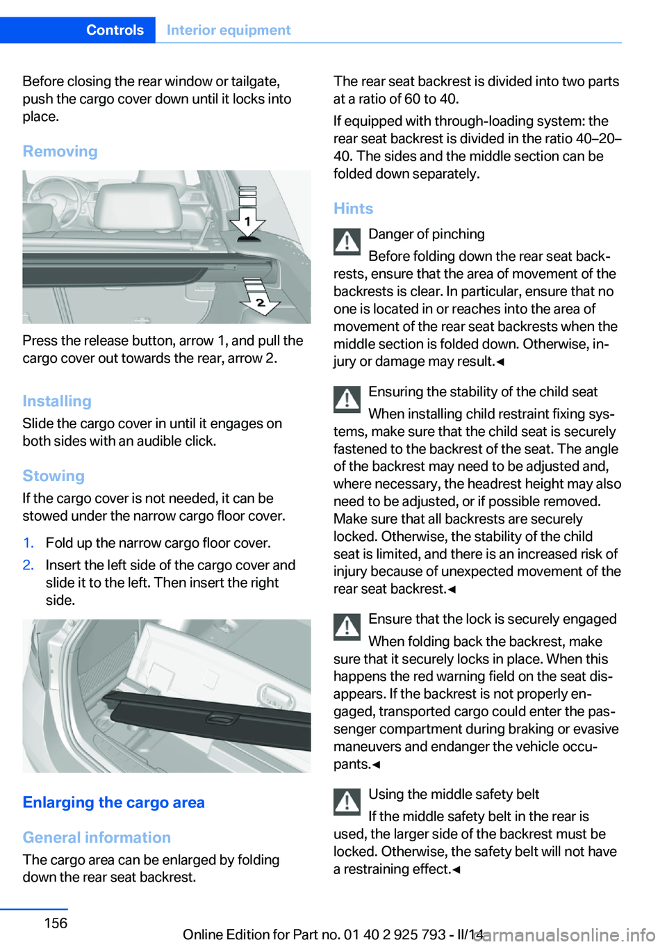
Press the release button, arrow 1, and pull the
cargo cover out towards the rear, arrow 2.
Installing Slide the cargo cover in until it engages on
both sides with an audible click.
Stowing
If the cargo cover is not needed, it can be
stowed under the narrow cargo floor cover.
1.Fold up the narrow cargo floor cover.2.Insert the left side of the cargo cover and
slide it to the left. Then insert the right
side.
Enlarging the cargo area
General information
The cargo area can be enlarged by folding
down the rear seat backrest.
The rear seat backrest is divided into two parts
at a ratio of 60 to 40.
If equipped with through-loading system: the
rear seat backrest is divided in the ratio 40–20–
40. The sides and the middle section can be
folded down separately.
Hints Danger of pinching
Before folding down the rear seat back‐
rests, ensure that the area of movement of the
backrests is clear. In particular, ensure that no
one is located in or reaches into the area of
movement of the rear seat backrests when the
middle section is folded down. Otherwise, in‐
jury or damage may result.◀
Ensuring the stability of the child seat
When installing child restraint fixing sys‐
tems, make sure that the child seat is securely
fastened to the backrest of the seat. The angle
of the backrest may need to be adjusted and,
where necessary, the headrest height may also
need to be adjusted, or if possible removed.
Make sure that all backrests are securely
locked. Otherwise, the stability of the child
seat is limited, and there is an increased risk of
injury because of unexpected movement of the
rear seat backrest.◀
Ensure that the lock is securely engaged
When folding back the backrest, make
sure that it securely locks in place. When this
happens the red warning field on the seat dis‐
appears. If the backrest is not properly en‐
gaged, transported cargo could enter the pas‐
senger compartment during braking or evasive
maneuvers and endanger the vehicle occu‐
pants.◀
Using the middle safety belt
If the middle safety belt in the rear is
used, the larger side of the backrest must be
locked. Otherwise, the safety belt will not have
a restraining effect.◀Seite 156ControlsInterior equipment156
Online Edition for Part no. 01 40 2 925 793 - II/14
Page 158 of 244
5.Fold open the front covers on the head‐
liner.6.Quickly pull out the partition net and insert
it into the brackets as for a normal cargo
area, refer to page 157. If the partition net
becomes blocked when it is pulled out, al‐
low it to retract and then pull it out quickly
again.
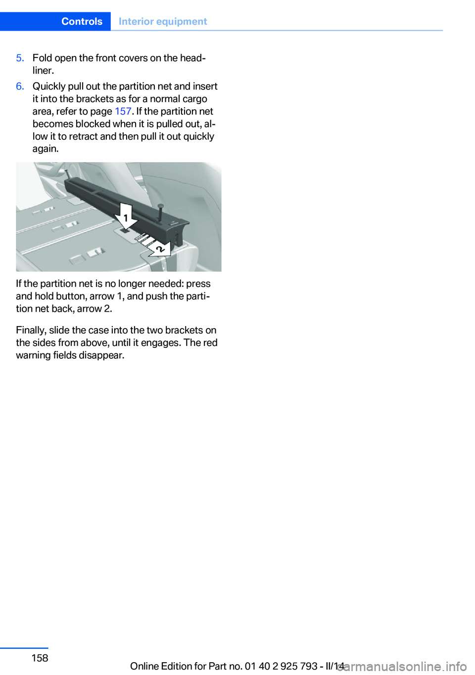
If the partition net is no longer needed: press
and hold button, arrow 1, and push the parti‐
tion net back, arrow 2.
Finally, slide the case into the two brackets on
the sides from above, until it engages. The red
warning fields disappear.
Seite 158ControlsInterior equipment158
Online Edition for Part no. 01 40 2 925 793 - II/14
Page 176 of 244
In addition, context-sensitive instructions can
be displayed that assist in driving in a manner
that optimizes fuel consumption.
In the instrument display, the extension of the
range achieved by this can be displayed as a
bonus range.
At a glance The system includes the following
EfficientDynamics functions and displays:▷ECO PRO bonus range, refer to page 176.▷ECO PRO tips driving instruction, refer to
page 177▷ECO PRO climate control, refer to
page 176.▷ECO PRO coasting driving status, refer to
page 178.▷ECO PRO driving style analysis, refer to
page 179.
Activate ECO PRO
Press button repeatedly until ECO
PRO is displayed in the instrument
cluster.
Configuring ECO PRO
Via the Driving Dynamics Control
1.Activate ECO PRO.2."Configure ECO PRO"3.Configure the program.
Via the iDrive
1."Settings"2."ECO PRO mode"
Or
1."Settings"2."Driving mode"3."Configure ECO PRO"
Configure the program.
ECO PRO Tip▷"Tip at:":
Set ECO Pro speed at which an ECO PRO
Tip is to be displayed.▷"ECO PRO speed warning":
A reminder is displayed if the set ECO PRO
speed is exceeded.
Coasting
Fuel-efficiency can be optimized by disengag‐
ing the engine and Coasting, refer to
page 178, with the engine idling.
This function is only available in ECO PRO
mode.
ECO PRO climate control
"ECO PRO climate control"
The climate control is adjusted to be fuel-effi‐
cient.
By making a slight change to the set tempera‐
ture, or slowly adjusting the rate of heating or
cooling of the passenger compartment, fuel
consumption can be economized.
The outputs of the seat heater and the exterior
mirror heating are also reduced.
The exterior mirror heating is made available
when outside temperatures are very cold.
ECO PRO potential
The percentage of potential savings that can
be achieved with the current configuration is
displayed.
Display in the instrument cluster
ECO PRO bonus range An extension of the range can
be achieved by an adjusted driv‐
ing style.
This may be displayed as the
bonus range in the instrument
cluster.
Seite 176Driving tipsSaving fuel176
Online Edition for Part no. 01 40 2 925 793 - II/14
Page 200 of 244
Hood
Hints Working in the engine compartment
Never attempt to perform any service or
repair operations on your vehicle without the
necessary professional technical training.
If you are unfamiliar with the statutory guide‐
lines, have any work on the vehicle performed
only by a service center.
If this work is not carried out properly, there is
the danger of subsequent damage and related
safety hazards.◀
Never reach into the engine compart‐
ment
Never reach into the intermediate spaces or
gaps in the engine compartment. Otherwise,
there is risk of injury, e.g., from rotating or hot
parts.◀
Fold down wiper arm
Before opening the hood, ensure that the
wiper arms are against the windshield, or this
may result in damage.◀
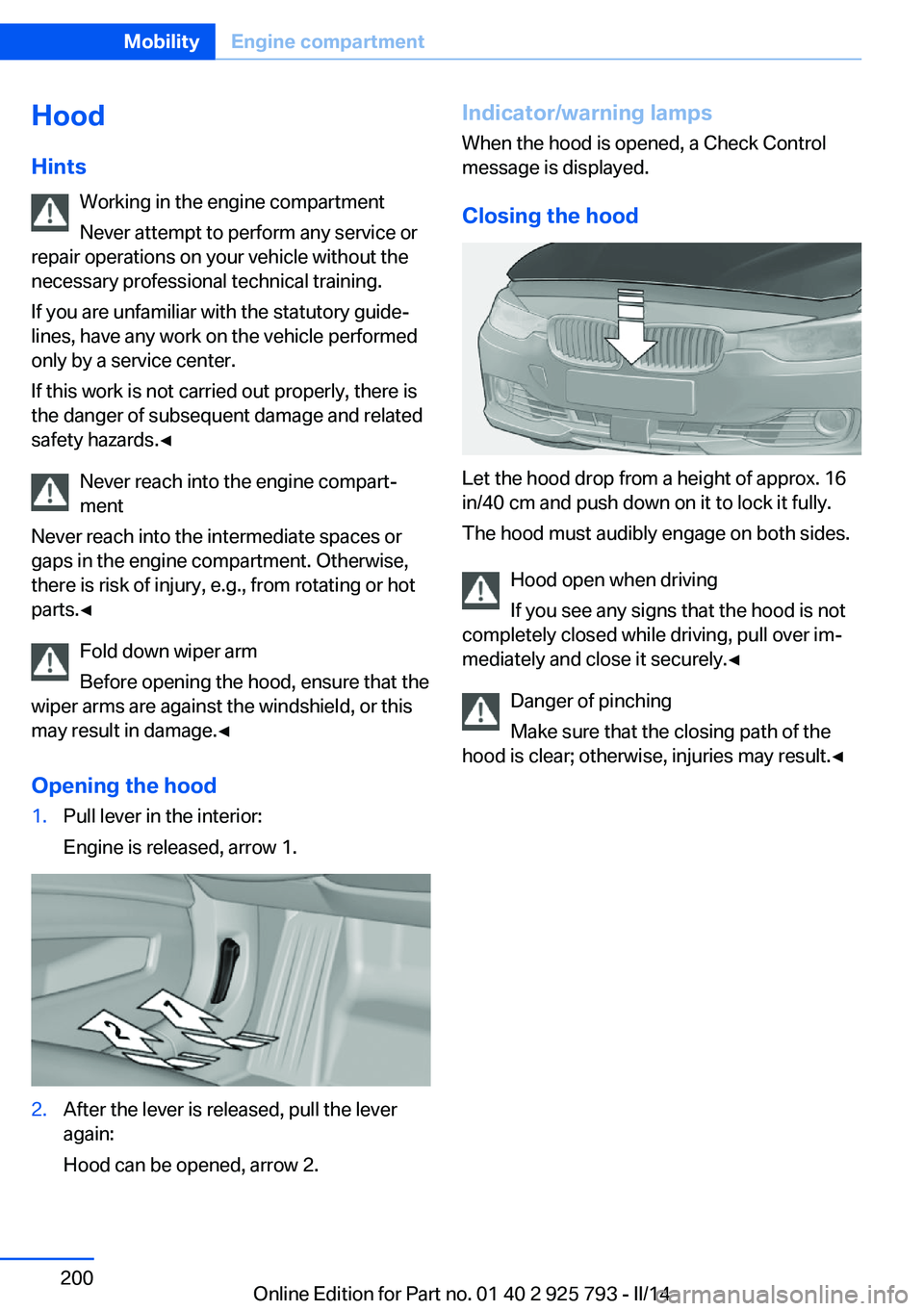
Opening the hood1.Pull lever in the interior:
Engine is released, arrow 1.2.After the lever is released, pull the lever
again:
Hood can be opened, arrow 2.Indicator/warning lamps
When the hood is opened, a Check Control
message is displayed.
Closing the hood
Let the hood drop from a height of approx. 16
in/40 cm and push down on it to lock it fully.
The hood must audibly engage on both sides.
Hood open when driving
If you see any signs that the hood is not
completely closed while driving, pull over im‐
mediately and close it securely.◀
Danger of pinching
Make sure that the closing path of the
hood is clear; otherwise, injuries may result.◀
Seite 200MobilityEngine compartment200
Online Edition for Part no. 01 40 2 925 793 - II/14
Page 202 of 244
General information
A detailed measurement is only possible with
certain engines.
Requirements▷Vehicle is on level road.▷Manual transmission: shift lever in neutral
position, clutch and accelerator pedals not
depressed.▷Automatic transmission: selector lever in
selector lever position N or P and accelera‐
tor pedal not depressed.▷Engine is running and is at operating tem‐
perature.
Performing a detailed measurement
In order to perform a detailed measurement of
the engine oil level:
1."Vehicle Info"2."Vehicle status"3. "Measure engine oil level"4."Start measurement"
The oil level is checked and displayed via a
scale.
Duration: approx. 1 minute.
Adding engine oil General information
Switch off the ignition and safely park the vehi‐
cle before engine oil is added.
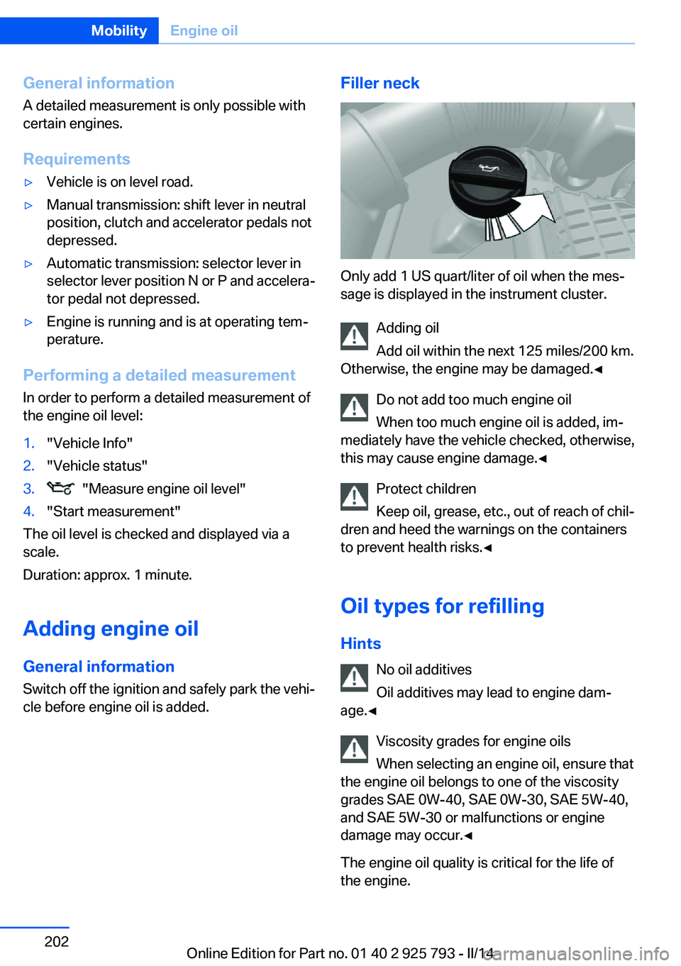
Filler neck
Only add 1 US quart/liter of oil when the mes‐
sage is displayed in the instrument cluster.
Adding oil
Add oil within the next 125 miles/200 km.
Otherwise, the engine may be damaged.◀
Do not add too much engine oil
When too much engine oil is added, im‐
mediately have the vehicle checked, otherwise,
this may cause engine damage.◀
Protect children
Keep oil, grease, etc., out of reach of chil‐
dren and heed the warnings on the containers
to prevent health risks.◀
Oil types for refilling
Hints No oil additives
Oil additives may lead to engine dam‐
age.◀
Viscosity grades for engine oils
When selecting an engine oil, ensure that
the engine oil belongs to one of the viscosity
grades SAE 0W-40, SAE 0W-30, SAE 5W-40,
and SAE 5W-30 or malfunctions or engine
damage may occur.◀
The engine oil quality is critical for the life of
the engine.
Seite 202MobilityEngine oil202
Online Edition for Part no. 01 40 2 925 793 - II/14
Page 206 of 244
correspondingly trained personnel and other
authorized persons. Otherwise, use may result
in operating problems for the vehicle.◀
Position
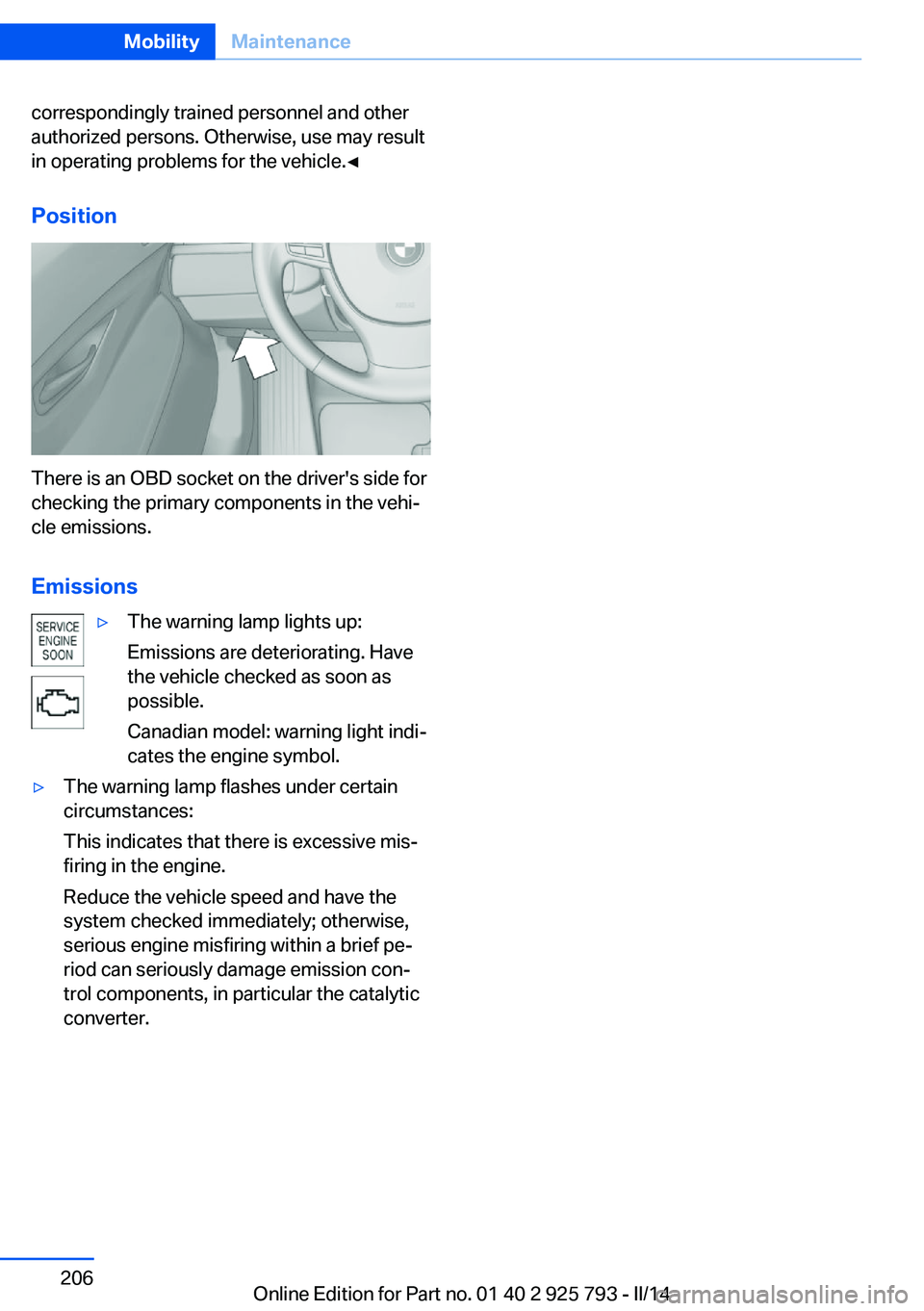
There is an OBD socket on the driver's side for
checking the primary components in the vehi‐
cle emissions.
Emissions
▷The warning lamp lights up:
Emissions are deteriorating. Have
the vehicle checked as soon as
possible.
Canadian model: warning light indi‐
cates the engine symbol.▷The warning lamp flashes under certain
circumstances:
This indicates that there is excessive mis‐
firing in the engine.
Reduce the vehicle speed and have the
system checked immediately; otherwise,
serious engine misfiring within a brief pe‐
riod can seriously damage emission con‐
trol components, in particular the catalytic
converter.Seite 206MobilityMaintenance206
Online Edition for Part no. 01 40 2 925 793 - II/14
Page 219 of 244
Breakdown assistanceVehicle equipment
All standard, country-specific and optional
equipment that is offered in the model series is
described in this chapter. Therefore, equip‐
ment is also described that is not available in a
vehicle, e. g., because of the selected optional
equipment or country variant. This also applies
for safety-related functions and systems.
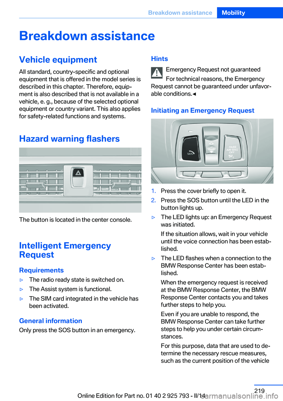
Hazard warning flashers
The button is located in the center console.
Intelligent Emergency
Request
Requirements
▷The radio ready state is switched on.▷The Assist system is functional.▷The SIM card integrated in the vehicle has
been activated.
General information
Only press the SOS button in an emergency.
Hints
Emergency Request not guaranteed
For technical reasons, the Emergency
Request cannot be guaranteed under unfavor‐
able conditions.◀
Initiating an Emergency Request1.Press the cover briefly to open it.2.Press the SOS button until the LED in the
button lights up.▷The LED lights up: an Emergency Request
was initiated.
If the situation allows, wait in your vehicle
until the voice connection has been estab‐
lished.▷The LED flashes when a connection to the
BMW Response Center has been estab‐
lished.
When the emergency request is received
at the BMW Response Center, the BMW
Response Center contacts you and takes
further steps to help you.
Even if you are unable to respond, the
BMW Response Center can take further
steps to help you under certain circum‐
stances.
For this purpose, data that are used to de‐
termine the necessary rescue measures,
such as the current position of the vehicleSeite 219Breakdown assistanceMobility219
Online Edition for Part no. 01 40 2 925 793 - II/14