2014 AUDI RS7 SPORTBACK ad blue
[x] Cancel search: ad bluePage 114 of 292
112 Park in g s ystems
the next to last segment is disp layed . Obsta
cles in the collision area, includ ing those out
side of the vehicle 's path, are shown in red. Do
not continue driving farther forward or in re
verse
q .&. in General informa tion on
page 110 , q (f) in General information on
page 110 .
Rear view camera
Introduction
Applies to vehicles: with pa rkin g system p lus wit h rear
view ca mera
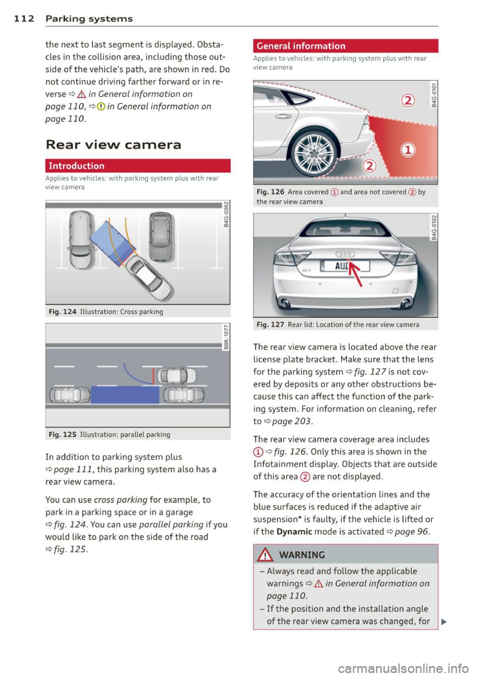
Fig. 124 Ill ustration: C ross pa rking
Fig. 125 Ill ustrat ion: paralle l park ing
In addition to parking system p lus
q page 111, this parking system also has a
rear view camera .
You can use
cross parking for example, to
park in a parking space or in a garage
q fig. 124 . You can use parallel parking if you
wou ld like to park on the side of the road
c::> fig . 125 .
General information
Applies to vehicles : wit h parking system plus with rear
v iew camera
Fig. 1 26 Area cover ed © and area not cover ed@ by
the rea r view ca mera
F ig. 127 Re ar lid: Location o f th e rear view camera
N 0 q
Cl
~
The rear v iew camera is located above the rear
license plate bracket. Make sure that the lens
for the parking system
c::> fig . 12 7 is not cov
ered by deposits or any other obst ruct ions be
ca use this can affect the fun ction of the park
i ng system. For informat ion on cleaning, refer
to
q page 203.
The rear v iew camera coverage area includes
@ c::> fig. 126 . Only this area is shown in the
Infot ainment display . Objects tha t are outside
of this area @are not displayed .
The accuracy of the orientation lines and the
blue surfaces is reduced if the adapt ive a ir
suspension* is faulty, if the vehicle is lifted or
if the
Dynam ic mode is activa ted c::> page 96.
A WARNING ~
-Always read and follow the applicable
warnings
c::> .&. in General information on
page 110.
- If the position and t he installation angle
-
of the rear view camera was changed, for IJl>
Page 116 of 292
114 Parking systems
Cross parking
Applies to vehicles: with park ing system p lus w it h rear
view ca mera
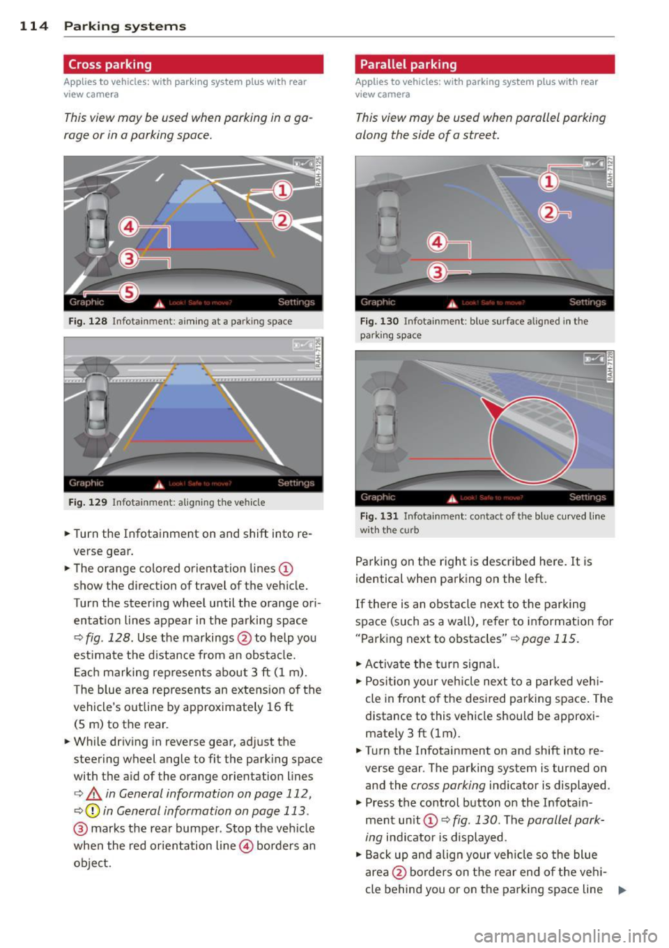
This view may be used when parking in a ga
rage or in a parking space.
F ig. 128 Infotainment: aim ing at a parking space
Fig. 129 Infotainment : aligning the ve hicle
... Turn the Infotainment on and shift into re
verse gear.
... The orange colored orientation lines
(D
show the direction of travel of the vehicle.
Turn the steering wheel until the orange ori
entat ion lines appear in the parking space
c:::> fig. 128. Use the markings @to help you
est imate the distance from an obstacle.
Each marking represents about 3 ft (1 m).
The blue area represents an extens ion of the
vehicle's out line by approximately 16 ft
(5 m) to the rear.
... While driving in reverse gear, adjust the
steering wheel angle to fit the parking space
with the aid of the orange orientation lines
c:> & in General information on page 112,
c:::> @ in General information on page 113 .
@ marks the rear bumper . Stop the veh icle
when the red orientation line@ borders an
object.
Parallel parking
Applies to vehicles : wit h parking system pl us with rear
v iew camera
This view may be used when parallel parking
along the side of a street.
Fig . 130 Infotainment : blue surface aligned in the
park ing space
Fig. 131 Infotainme nt: contact of the blue curved lin e
w ith the curb
Parking on the right is described here. It is
identical when parking on the left.
If there is an obstacle next to the parking
space (such as a wall), refer to information for
"Parking next to obstacles"
c:::> page 115.
"' Activate the turn signal.
"'P osit ion your veh icle next to a parked vehi
cle in front of the desired parking space. The
distance to this vehicle should be approxi
mate ly 3 ft (lm) .
... Turn the Infotainment on and shift into re
verse gear . The parking system is turned on
and the
cross parking indicator is displayed.
"' Press the control button on the Infota in
ment un it
(D c:::> fig. 130 . The parallel park
ing
indicator is displayed.
"' Back up and align your vehicle so the blue
area @borders on the rear end of the veh i-
cle behind you or on the parking space line ..,.
Page 117 of 292
r::> & in General information on page 112,
r::>(D in General information on page 113 .
The blue area represents an extens ion of the
vehicle's outline by approximately 16 ft
(5 m) to the rear . The long side of the blue
area should be on the curb . The entire blue
area must fit into the parking space.
• With the veh icle stopped, turn the steering
wheel to the right as far as it w ill go.
• Back in to the park ing space u ntil the b lue
curve
r::> fig . 131 touches the curb r::> & in
General information on page 112,
r::> (D in
General information on page 113 .
Stop the
vehicle.
• With the veh icle stopped , turn the steer ing
whee l to the left as far as it will go .
• Continue to back into the parking space un
t il the vehicle is parked pa rallel to the cu rb
r::> & in General information on page 112,
r::> (D in General information on page 113 .
@ marks the rear bumper. Stop the veh icle,
at the latest, when the red orientation line
@ borders an object. Keep an eye on the
front of your vehicle whi le do ing th is .
Pa rking next to obstacles
If there is an obstacle (s uc h a s a wall) next to
the par king space, position the veh icle so
there is more space o n that s ide. Position the
l ong side of the blue s urface so that there is
sufficient space from the obstacle . The sur
face must not be to uch ing . You will also need
to star t turning the steer ing wheel much ear
lier . The blue curve
r::>fig .131 must not touch
the obstacle and should have sufficient room.
(D Note
Remember to maintain sufficient clear
ance from the curb to avoid damag ing the
wheel rims .
(D Tips
The left or right orientation lines and sur
faces will be displayed, depend ing on the
turn sig na l being used.
P arking systems 115
Peripheral cameras
Introduction
Applies to vehicles: with parking system plus with periph
eral cameras
In add ition to parking system plus
¢
page 111, this parking system conta ins pe
ripheral cameras . Depending on the vehicle
equipment , you are ass isted by vario us views
su ch a s p eriphera l view, corne r views a t the
fron t and rear of the veh icle, and views di rect
ly in front of or behind t he vehicle .
General information
Applies to vehicles: with parking system plus with periph
eral cameras
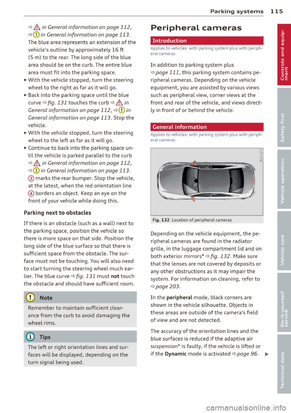
F ig . 1 32 Locat io n of per ip hera l ca meras
Depending on the vehicle equipment, the pe
ripheral cameras are found in the radiator
grille, in the luggage compartment lid and on
both exterior mirrors* ¢
fig. 132. Make su re
that the lenses a re not covered by depos its o r
any other obstr uctions as it may impa ir t he
system. For info rmat io n on clean ing, refe r to
¢ page 203.
In the peripheral mode , b lack corners are
shown in the ve hicle silhouette . Objects in
these a reas a re outside of the came ra's field
of view and are not detec ted .
The accuracy of the orientation lines and the
bl ue surfaces is reduced if the adaptive a ir
suspension* is faulty, if the vehicle is l ifted or
if t he
D ynamic mode is activa ted ¢ page 96. ..,.
Page 120 of 292

118 Parking systems
orientation line * borders an object¢.&. in
Gen eral information on page 116 .
Rear
Appl ies to vehicles: with parking system plus and rear
mode
F ig. 139 In fot ainm ent: rear mode
Th is view as sists you for example, in using the
f ull maneuvering range behind the veh icle .
The area beh ind the veh icle is d isplayed . The
vehicle surroundings are shown in the left
area of the display . You can switch between
optical d isplay and camera image*
¢ page 117.
.,. Select the @symbol with the control knob .
You can choo se between three different views
in this mode .
.,. To cross park or parallel park, press the ®
control button on the unit repeated ly until
the symbol for the desired mode is selected .
Cross parking
Applies to vehicles: with parking system p lus and rear
mode
T his view may be used when parking in a ga
rage or in a parking space.
Fi g. 140 Infot ainment: a im ing at a parkin g space
Fig . 14 1 Info ta inme nt: al ign ing t he ve hicle
Requ irement: cros s parking is selected
¢ page 118 .
.,. The orange colored orientation lines(!)
show the direction of travel of the vehicle .
Turn the steering wheel until the orange ori
entation lines appear in the parking space
¢ fig . 140 . Use the mark ings @to help you
estimate the distance from an obstacle .
Ea ch mar king represe nts about 3
ft (1 m).
The blue area represents an ex tension of the
veh icle's ou tline by approximate ly 16 ft
(S m) to the rear.
.,. Whi le driving in reverse gear, adjust the
steer ing whee l angle to fit the parking space
w ith the aid of the orange orientat ion lines
¢ .&. in General information on page 116,
¢ (Din General information on page 116 .
@ marks the rear bumper. Stop the vehicle
when the red orienta tion line @ borders an
obs ta cl e
¢ .&. in General information on
page 112.
Page 121 of 292
Parallel parking
Applies to vehicles: with parking system plus and rear
mode
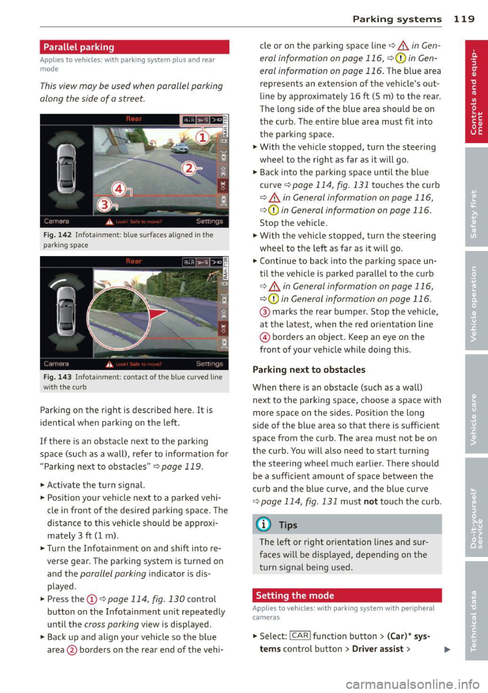
This view may be used when parallel parking
along the side of a street.
Fig. 1 42 Infotainment: blue su rfaces aligned in the
parking space
F ig. 1 43 Infota inmen t: contact of the blue curved line
wi th th e curb
Park ing on the right is described he re. It is
ident ical when parking on the left .
I f there is an obstacle next to the park ing
space (such as a wall), refer to information for
"Parking next to obstacles"
c::> page 119.
~ Activate the turn s ignal.
~ Position your vehicle next to a parked vehi
cle in front of the desired parking space . T he
distance to th is vehicle should be approxi
mately 3 ft (1 m).
~ Turn the Infotainment on and shift into re
verse gear. The parking system is turned on
and the
parallel parking indicator is dis
played .
~ Press the@¢ page 114 , fig. 130 control
button on the Infotainment un it repeatedly
unt il the
cross parking view is displayed.
~ Backup and align yo ur vehicle so the blue
area @ borders on the rear end of the vehi-
Parking systems 119
cle or on the parking space line c::> A in Gen
eral information on page 116, c::>(I)in Gen
eral information on page 116.
The blue area
represents an extension of the vehicle 's out
line by approximately 16 ft (5 m) to the rear.
The long side of the blue area should be on
the curb . The entire blue area must fit into
th e parking space .
~ With the vehicle stopped, turn the stee ring
wheel to t he righ t as fa r as it will go.
~ Back into the parking space unt il the blue
curve
c::> page 114, fig. 131 to uches the curb
c::> A in General information on page 116,
c::>(D in General information on page 116.
Stop the vehicle.
~ With the vehicle stopped, turn the steering
wheel to the left as far as it w ill go.
~ Continue to back into the parking space un
til the vehicle is parked parallel to the curb
c::> ..&. in General information on page 116,
c::> (Din General information on page 116.
@ marks the rear bumper. Stop the vehicle,
at the latest, when the red orientation line
@ borders an object . Keep an eye on the
front of your vehicle while do ing this .
Parking next to obstacles
When there is an obstacle (such as a w all)
next to the parking space, choose a space with
more space on the sides . Positio n the long
side of the blue area so that there is sufficient
space from the curb. The area must not be on
the curb. You will also need to start turning
the steering wheel much earlier . T here should
be a sufficient amount of space between the
c ur b and the bl ue curve, and the b lue curve
c::> page 114, fig . 131 m ust no t touch the curb.
@ Tips
The left o r right orientation lines and sur
faces w ill be disp layed, depending on the
turn s ignal being used .
Setting the mode
Applies to vehicles: with parking system with peripheral
cameras
~ Select: ! CAR ! function button> (Car) * sy s
tems
control button > Driver assist >
Page 122 of 292
120 Parking systems
Parking aid > Change to front/rear > Auto
or Manual.
Auto -
This view behind the vehicle (Rear
mode) is displayed automatically when you
shift into reverse . This view in front of the ve
hicle
( Front mode) is disp layed automatically
when you shift into the forward gears.
Manual -This view behind the vehicle (Rear
mode) is a lways disp layed when you turn on
the system.
Adjusting the display and the warning tones
Applies to vehicles: with parking system plus/rear view
camera/peripheral cameras
The display and warning tones can be adjust
ed in the Infotainment.
.. Se lect: I CAR ! function button > (Car)* sys
tems
control button > Driver assist > Park
ing aid.
Display
On* -
optical display is shown for the parking
system plus, rear view came ra image is shown
for parking system plus with rear view cam
era*.
Off -when the parking system is switched off,
on ly audib le signals are given.
Warning tones
Front volume -
Volume for the front area
Rear volume -Volume for the rear area
Front frequency -Frequency for the front area
Rear frequency -Frequency for the rear area
Music volume while parking -When the park
ing system is tu rned on, the volume of the au
dio/video source is lowered.
The newly adjusted value is briefly heard from
the signa l gene rator .
(D Tips
-The warning tones can a lso be adjusted
directly from the visual display or the rear v
iew camera* image. Simply press
the
Settings control button.
- Changed settings are activated when the
parking system is switched on again.
- The settings are automatically stored
and assigned to the remote cont rol key
that is in use .
Error messages
Applies to vehicles: with parking system plus/rear view
camera/peripheral cameras
T here is an error in the system if the LED in
the
p, q~ button is blinking and you hear a con
tinuous alarm for a few seconds after switch
ing on the parking system or when the park
ing system is already activated. If the error is
not corrected before you switc h
off the igni
tion, the LED in the
Pwi button will blink the
next t ime you sw itch on the parking system by
shifting into reverse.
Parking system plus
If a sensor is fa ulty, the~ symbol will appear
in front of/behind the vehicle in the Infotain
ment display. If a rear sensor is faulty, only
obstacles that are in areas @ and ® are
shown
Q page 111, fig. 121. If a front sensor
is faulty, only obstacles that are in areas ©
and @are shown.
Peripheral cameras*
There is also a system error if:
- the
i:80 ·• symbol appears in the display and
the corresponding display area is shown in
blue. The camera is not working in this area.
- all segments aro und the vehicles are red or
if no segments are displayed.
Drive to your authorized Audi dealer or au
thorized repa ir facility immed iately to have
the malfunction corrected.
Page 263 of 292

No. Equ ipment Amps
4 Suspension control system sen-s sor
s
E
lectronic Stabilization Cont rol
s (ESC) module
6 Climate control
5
7 Adaptive cruise control 10
8
Airbag control module, front
5
passenger's seat sensor system
9 Gateway 5
Homelink (garage doo r opener),
10 night vis ion system cont ro l 5
module
11 Image
processing (active lane
10
ass ist, adaptive cruise control)
12 Dynamic steering 5
13 Terminal 15 in
the instrument
15
panel
14 Terminal 15
in the luggage com-
partment 30
15 Terminal 15
(engine)
15
16 Starter 40
Fu se pa nel ® (b rown )
No . Equipment Amps
1 Gateway
5
2 C limate control 10
3 E
lectronic Stabili zation Contro l
10
(ESC) module
4 Fron
t door (driver 's side)
30
s
Power seat adjustment (driver's
7,5
seat)
6 Dynam
ic steering
35
7 Sunroof 20
8
Rear door control module (driv-
15
er 's side)
9 Lumbar support (
Front passen-
s ger seat)
10 Tire pressure
monitoring system
5
11 Su
nroof, rear spoi ler (Sportba ck)
20
12 Driver
door control module
15
Fuse s and bulb s 261
Fuse pan el© (r e d )
No . Equipment
2 Fuel pump
3 Brake light sensor/brake pedal
sensor system
AdBlue control module (Diesel)/
4 Engine acoust ics
5 Left rear door cont rol modu le
6 Power seat adjustment
(pas-
senge r's seat)
7 Horn
8 Windshield wiper motor
9 Light/rain sensor, heater
for vid-
eo camera in windscreen
10 L umba r support (driver seat)
1 1 Front
passenger door control
modu le
12 Right rea r door cont rol modu le
Front passenger side cockpit fuse
assignment Amp
s
25
5/5
5/7,S 30
7,5 15
30
s
5
15
15
F ig . 217 Front passenger side cockpit: fuse pa nel w it h
plast ic brac ket
Fuse panel @ (bla ck)
No . Equipment Amps
1 Head-up
Display
5
2 MMI Display 5
3 CO/DVD changer
5
4 MMI unit/drives 7,5
5 Chip
card reader (not in all coun-
5
tries)
6 Instrument
cluster
5
7 Steering column switch module 5 ...