2014 AUDI RS7 SPORTBACK stop start
[x] Cancel search: stop startPage 99 of 292
(dynamic). The goal is a high level of agility
and ability to accelerate on curves. The vehicle
is very responsive to steering.
Curve light*
The curve light adapts to driving on curves.
The pivoting action and the lighting are also
adapted to the mode.
Adaptive cruise control*
The behavior when accelerating can be adjust
ed from comfo rtable to sporty, depending on
the drive se lect mode . Adaptive cruise control
also responds to the driving behavior of the
vehicle ahead in a more conservative or sporty
manner .
Engine sound
The sound of the engine is adapted to these
l ected mode and ranges from subtle to sporty.
(D Note
-Make sure there is enough clearance
above and below the vehicle when park
in g. The height of the vehicle can change
once it is parked due to temperature
fluctuations, changes to the load condi
tions and changes to the driving modes,
which can affect clearance.
- When transporting the vehicle on a car
carrier, train, ship or by other means, on
ly tie the veh icle down at the running
surface of the tires, which is the outer
circumference. Securing the vehicle at
the axle components, suspension struts
or tow ing eyes is not permitted because
the pressure in the air suspension struts
can change during transport. The vehicle
may not be secured sufficiently if this
happens.
(D} Tips
- In some models, the maximum vehicle
speed can only be reached in the
Auto
and Dynamic modes.
- Se lecting the
Dynamic mode results in
spo rty shifting characteristics. The S
gear position engages automatically .
Audi drive select 97
-In vehicles that have dynamic steering*,
operating noise is heard when starting or
stopping the engine. This does not indi
cate a problem.
Selecting the driving mode
You can choose between Comfort, Auto, Dy
namic and Individual.
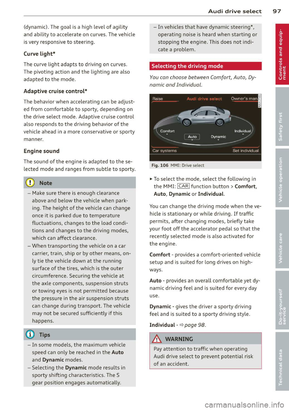
Fig. 106 MMI: Drive select
.,. To select the mode, select the following in
the
MMI: ICARI function button> Comfort,
Auto, Dynamic or Individual.
You can change the driving mode when the ve
hicle is stationary or wh ile driving. If traffic
permits, after changing modes, briefly take
your foot off the accelerator pedal so that the
recently selected mode is also activated for
the engine.
Comfort · provides a comfort-oriented veh icle
setup and is suited for long drives on h igh
ways.
Auto · provides an overall comfortable yet dy
nam ic dr iving feel and is suited for every day
use .
Dynamic -gives the driver a sporty driving
feel and is suited to a sporty driving style.
Individual -~page 98.
&_ WARNING
Pay attention to traffic when operating
Audi drive select to prevent potential risk
of an acc ident.
-
Page 108 of 292
106 Automatic Transmission
lever is left in N (Neutral) for more than ap
proximately 2 second, without the brake ped
a l being pressed .
Release button
The release button on the selector lever pre
vents the lever from being accidentally shifted
into certain positions. Depending on the direc
tion of the shift, the se lector lever locks at d if
ferent positions. The positions are highlighted in the illustration
c:;, fig. 116.
Driving the automatic transmission
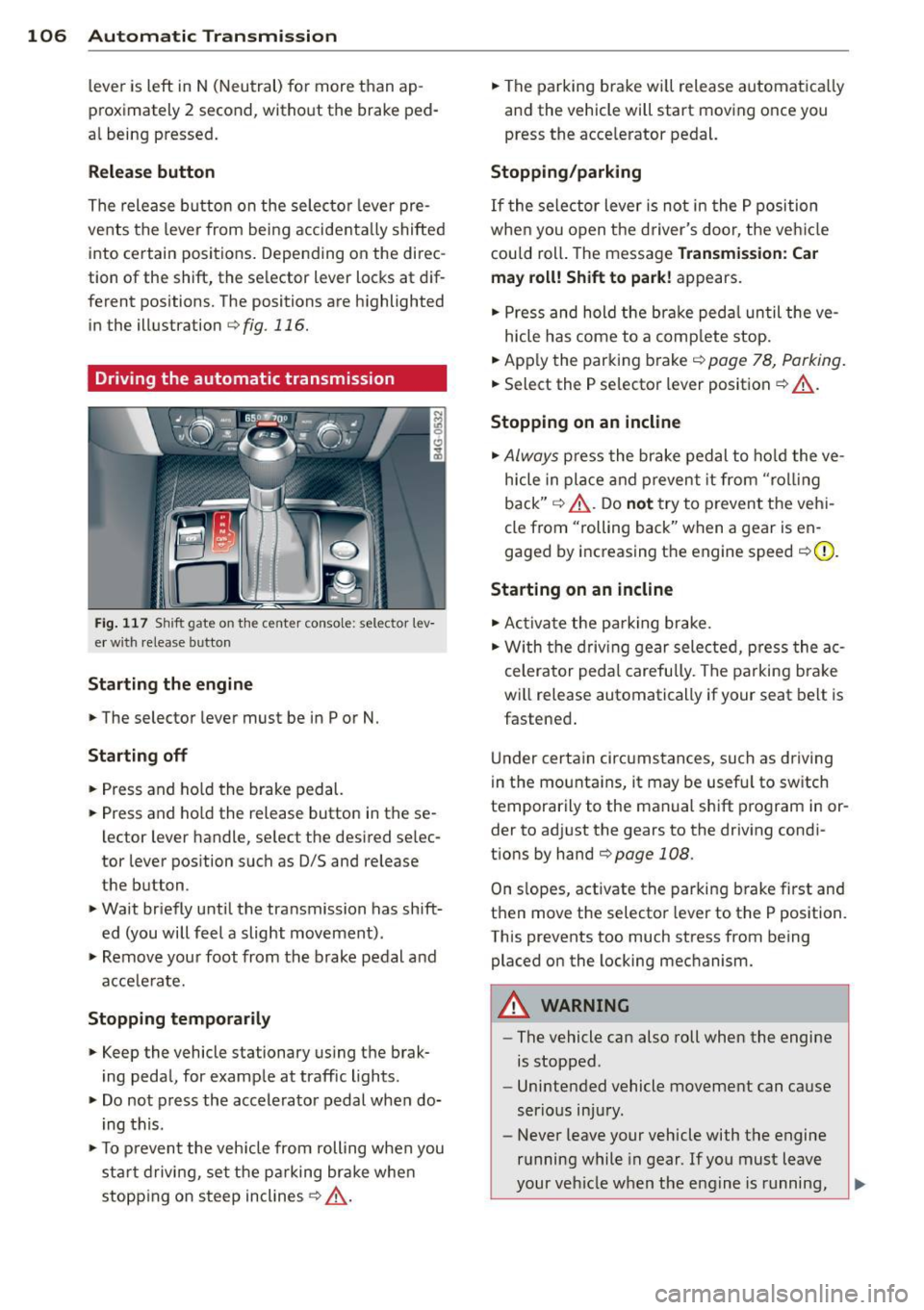
Fig. 117 Sh ift gate on the center conso le: selector lev
er w ith release button
Starting the engine
,.. The selector lever must be in P or N.
Starting off
,.. Press and ho ld the brake pedal.
,.. Press and ho ld the release button in these
lector lever handle, se lect the desired se lec
tor lever position such as 0/5 and release
the button .
,.. Wait briefly until the transmission has shift
ed (you will feel a slight movement) .
,.. Remove your foot from the brake pedal and
acce le rate.
Stopping temporarily
,.. Keep the vehicle stationary us ing the brak
ing peda l, for example at traffic lights.
,.. Do not press the accelerator pedal when do
ing this .
,.. To prevent the veh icle from rolling when you
sta rt driving, set the parking brake whe n
stopping on steep inclines
c:;, _& .
,.. The parking brake will release automatica lly
and the vehicle will start moving once you
press the acce lerator pedal.
Stopping/parking
If the sele ctor lever is not in the P position
whe n you open t he driver's door, the veh icle
could roll. The message
Transmission: Car
may roll! Shift to park!
appears.
,.. Press and hold the brake pedal until the ve-
hicle has come to a complete stop.
,.. App ly the parking brake
c::> page 78, Parking.
,.. Select the P selector lever position c:;, _& .
Stopping on an incline
,.. Always press the brake pedal to hold the ve
hicle in place and prevent it from "rol ling
back"
c:;, _& . Do not try to prevent the vehi
cle from "rolling back" when a gear is en
gaged by increasing the engine speed
c::>(D .
Starting on an incline
,.. Activate the parking brake.
,.. With the driving gear selected, press the ac
celerator pedal carefully. The parking brake
will release automatically if your seat belt is
fastened .
Under certain circumstances, such as driving
in the mounta ins, it may be usefu l to sw itch
temporarily to the manual shift program in or
der to adj ust the gears to the driving condi
t ions by hand
c::>page 108 .
On slopes, activate the parking brake first and
then move the selector lever to the P position.
This prevents too much stress from being placed on the locking mechanism.
A WARNING
-
- The vehicle can also roll when the engine
is stopped .
- Unintended vehicle movement can cause
serious injury.
- Never leave your vehicle with the engine
running while in gear . If you must leave
your vehicle when the engine is running,
Page 121 of 292
Parallel parking
Applies to vehicles: with parking system plus and rear
mode
This view may be used when parallel parking
along the side of a street.
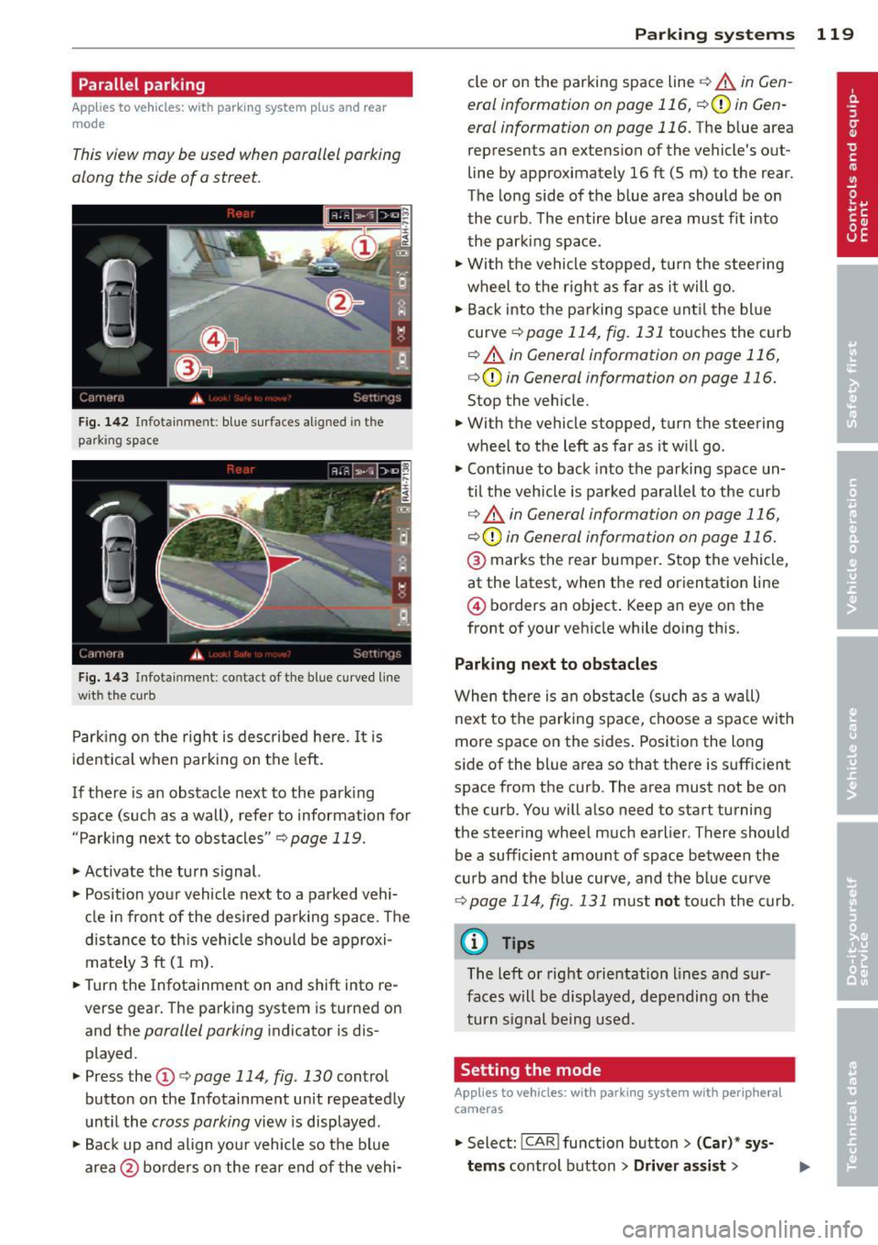
Fig. 1 42 Infotainment: blue su rfaces aligned in the
parking space
F ig. 1 43 Infota inmen t: contact of the blue curved line
wi th th e curb
Park ing on the right is described he re. It is
ident ical when parking on the left .
I f there is an obstacle next to the park ing
space (such as a wall), refer to information for
"Parking next to obstacles"
c::> page 119.
~ Activate the turn s ignal.
~ Position your vehicle next to a parked vehi
cle in front of the desired parking space . T he
distance to th is vehicle should be approxi
mately 3 ft (1 m).
~ Turn the Infotainment on and shift into re
verse gear. The parking system is turned on
and the
parallel parking indicator is dis
played .
~ Press the@¢ page 114 , fig. 130 control
button on the Infotainment un it repeatedly
unt il the
cross parking view is displayed.
~ Backup and align yo ur vehicle so the blue
area @ borders on the rear end of the vehi-
Parking systems 119
cle or on the parking space line c::> A in Gen
eral information on page 116, c::>(I)in Gen
eral information on page 116.
The blue area
represents an extension of the vehicle 's out
line by approximately 16 ft (5 m) to the rear.
The long side of the blue area should be on
the curb . The entire blue area must fit into
th e parking space .
~ With the vehicle stopped, turn the stee ring
wheel to t he righ t as fa r as it will go.
~ Back into the parking space unt il the blue
curve
c::> page 114, fig. 131 to uches the curb
c::> A in General information on page 116,
c::>(D in General information on page 116.
Stop the vehicle.
~ With the vehicle stopped, turn the steering
wheel to the left as far as it w ill go.
~ Continue to back into the parking space un
til the vehicle is parked parallel to the curb
c::> ..&. in General information on page 116,
c::> (Din General information on page 116.
@ marks the rear bumper. Stop the vehicle,
at the latest, when the red orientation line
@ borders an object . Keep an eye on the
front of your vehicle while do ing this .
Parking next to obstacles
When there is an obstacle (such as a w all)
next to the parking space, choose a space with
more space on the sides . Positio n the long
side of the blue area so that there is sufficient
space from the curb. The area must not be on
the curb. You will also need to start turning
the steering wheel much earlier . T here should
be a sufficient amount of space between the
c ur b and the bl ue curve, and the b lue curve
c::> page 114, fig . 131 m ust no t touch the curb.
@ Tips
The left o r right orientation lines and sur
faces w ill be disp layed, depending on the
turn s ignal being used .
Setting the mode
Applies to vehicles: with parking system with peripheral
cameras
~ Select: ! CAR ! function button> (Car) * sy s
tems
control button > Driver assist >
Page 123 of 292

Homelink
Universal remote
control
General information
Applies to vehicles: with Home link unive rsal remote con
tro l
The Homelink universal remote control can
be programmed with hand-held transmitters
from existing equipment
With Home link, you can control devices such
as the garage door, security systems, house
lights, etc. comfortably from the inside of you
vehicle.
Homelink makes it possible for you to replace
three different remote controls from devices
in your home with one universal remote . This
feature works for most garage door and exte rior door motor signals. Programmi ng the in
d iv idual remote control for your remote con
trol takes place near the center of the radiator
grille. There is a control module attached at
this location .
A one-t ime programming of the sensor must
be performed before you are able to use sys
tems with Homelink.
A WARNING , .,.
- Never use the Homelink transmitter
with any garage door opener that does
have not the safety stop and reverse fea
ture as required by federal safety stand
ards . Th is includes any garage door open
er model manufactured before April 1, 1982.
- A garage door opener which cannot de
tect an object, signaling the door to stop
and reverse does not meet current feder
al safety standards . Us ing a garage door
opener without these features increases
risk of serious injury or death.
- For safety reasons
never release the
parking brake or start the engine while
anyone is standing in front of the vehicle .
- A garage door or an estate gate may sometimes be set in motion when the
H ome link 121
Homelink remote control is being pro
grammed. If the device is repeatedly ac
tivated, this can overstrain motor and
damage its electrical components -an
overheated motor is a fire hazard!
- To avoid possible injuries or property
damage, please always make absolutely
certa in that no persons or objects are lo
cated in the range of motion of any
equipment being ope rated.
(D Tips
- If you would like additional information
on the Home link Universal Transce iver
I
Homel ink compatib le products, or to
purchase other accessories such as the
Homelink Lighting Package, please con
tact Homelink at 1-800-355 -3515 or on
the Internet at www. homelink.com.
- For Declaration of Comp liance to United
States FCC and Ind ustry Canada reg ula
tions~
page 2 76.
- For security reasons, we recommend that
you clear the programmed buttons be
fore selling the vehicle .
Operation
Applies to vehicles: with Homelink
Fig. 144 Headliner : cont rols
Req uirement: The bu ttons must be program
med
~ page 122.
.,. To open the garage door, press the program
med button . The LED @ will light up or
flash.
... To close the garage door , press the button
again .
II>
Page 216 of 292

214 Check ing and filling
- Always disconnect the battery.
- Never smoke or work near heaters or open flames . Fluids in the engine com
partment could start a fire.
- Keep an approved fire extinguisher im
mediately available.
- To avoid electrical shock and persona l in
jury while the engine is running or being started, never touch:
- Ignition cables
- Other components of the high voltage
electronic ignition system.
- If you must perform a check or repa ir
with the engine running:
- Fi rst, fully apply the parking bra ke,
move se lec to r lever to P (Pa rk) .
- Always use extreme caution to preven t
clot hing, jewe lry, or long h air from ge t
ting caught in the radiator fan, V -belts
or other moving parts, or from contact ing hot parts. Tie back hair before
start ing, and do not wear cloth ing that
will hang or droop into the eng ine.
- Min imize exposure to emission and
chemica l hazards¢ ,&..
A WARNING
California Propos ition 65 Warning:
- Engine exhaust, some of its constituents,
and certa in veh icle components conta in
or emit chemicals known to the State of
Califor nia to cause cancer and b irth de
fec ts a nd reproduct ive ha rm. In addition,
certain fluids conta ined in vehicles and
certa in prod ucts of co mponent wear co n
ta in o r emi t chemicals known to the
State o f Ca lifornia to cause can cer and
birth defects or ot her reproductive harm. -
Battery posts, terminals and re lated ac
cessories conta in lead and lead com
pounds, chemicals known to the State of
California to cause cance r and reproduc
tive harms. Wash hands after handling .
(D Note
When adding flu ids, always make sure that
they are poured into the proper conta iner
or f iller opening, otherwise serious dam
age to vehicle systems w ill occur.
® For the sake of the environment
To detect leaks in time, inspect the vehicle
floor pan from underneath regularly. If
you see spots from oil or other ve hicle flu
i ds, have yo ur vehicle inspected by a n au
thori zed Audi dea le r.
Closing the engine hood
.,. Pull the hood down un til the pressure from
t he struts is reduced.
.,. Let the hood drop down and latch in p lace .
Do not try to push it shut; it may fail to en
gage ¢&_ .
A WARNING
-
A hood that is not completely latched
could fly up and b lock your view while dr iv
ing.
- When you close the engine hood, check it
to make sure the safety catch has p roper
ly engaged. The hood sho uld be flush
with the surrou nding vehicle body pa rts.
- If you notice while driv ing t hat the hood
is not s ecured prope rly, stop at onc e and
close it.
Page 237 of 292
-Turn the valv e stem cap counter-clockwise
to remove it from the tire valve.
- Place the air pressure gauge on the valve.
- The tire pressures should only be checked
and adjus ted when the tires are cold . The
s li ght ly raised p ressures of warm tires must
not be reduced .
- Adjust the tire pressure to the load you are
carrying .
- Re insta ll the va lve stem cap on the valve.
When should I che ck the tire pres sur e?
The correct tire pressure is espec ially impor
tant at high speeds. The pressure should
therefo re be checked at least once a month
and a lways before start ing a journey.
When should I adjust the tire p re ssure s?
Adjust the tire pressure to the load you are
carry ing . After changing a wheel
o r replacing
wheels you have to adjust the tire pressures
on all wheels. In addition , you must then
store the new ti re pressu res in the t ire pres
sure monitoring system
r::!.> page 246 .
A WARNING
Incorrect tire pressures and/or underinf la
tion can lead sudden tire failure, loss of contro l, collision, serious persona l injury
or even death.
- When the warning symbo l
[ti] appears in
the instrument cl uster, stop and inspect
the tires.
- Incorrect tire pressure and/or underinfla
t ion can cause increased tire wear and
can affect the handling of the veh icle and
stopp ing ability .
- Incorrect tire pressures and/or underin
flation can also lead to sudden tire fa il
ure, including a blowout and sudden de
flation, causing loss of vehicle control.
- The driver is responsible for the correct
tir e pressures fo r all t ires on the vehicle .
T he applicable pressu re va lues are locat
ed on a stic ker on the drive r's side B-pil
lar .
- Only when a ll t ires on the vehicle are fi l
led to t he cor rect pressure, the ti re p res-
Tire s an d wheel s 235
sure monitor ing system can work cor
rectly.
- The use of incorrect tire pressure va lues
can lead to acc idents or other damage.
Therefore it is essential that the driver
observe the spec ified t ire pressure values
for the tires and the correct pressures for
the function of the t i re p ress ure monito r
ing system .
- Always inf late t ires to the recommended
a nd correct t ire p ress ure before dr iv ing
off.
- Driving with unde rinflated tires bend
mo re, lett ing t hem get too hot resulti ng
in tread separation, s udden tire failure
and loss of cont ro l.
- Excess ive speed and/overloadi ng can
cause heat b uild- up, sudden tire failure
a nd loss of cont rol.
- If the tire pressure is too low or too high,
the t ires will wear prema turely and the
veh icle w ill not handle well.
- If the tire is not fla t and you do not have
to ch ange a wheel immedia tely, drive a t
red uced speed to the nearest service sta
tion to check the t ire p ress ure and add
air as requi red.
(D Note
Dr iving w it h out valve stem c aps can c ause
damage to the tire valves . To prevent this,
a lways make sure that factory insta lled
va lve stem caps on all whee ls are sec urely
mounted on the valve .
@ For the sake of the env ironment
Un derinflated tires wi ll also increase the
fuel consumption .
Tires and vehicle load limits
There are limits to the amount of load or
weight that any vehicle and any tire can carry.
A vehicle that is overloaded will not handle
well and is mo re d iff icult to stop. Overloading
can not o nly lead to loss of vehicle control,
but can also damage important parts of the
vehicle and c an le ad to sudden tire fa ilu re, .,..
•
•
Page 248 of 292

246 Tires and wheels
Refer to ¢page 243 for mo re detailed infor
mation regarding winter tires .
Tire pressure
monitoring system
(D General notes
Each tire, including the spare (if provided) ,
should be checked monthly when cold and in
flated to the inflation pressure recommended by the vehicle manufacturer on the vehicle
placard or tire inflation pressure label. (If your
vehicle has tires of a different size than the
size indicated on the vehicle placard or tire in
flation pressure label, you shou ld determine
the proper tire inflation pressure for those
tires).
As an added safety feature, your vehicle has
been equipped with a tire pressure monitor ing
system (TPMS) that illuminates a low tire
p ressure telltale when one or more of your
tires is significantly under-inflated. According
ly, when the low tire pressure telltale illumi
nates, you should stop and check your tires as
soon as possible, and inflate them to the proper pressure. Driving on a significantly un
der-inflated tire causes the tire to overheat
and can lead to tire failure . Under -inflation al
so reduces fuel efficiency and tire tread life,
and may affect the vehicle's handling and
stopping ab ility.
Please note that the TPMS is not a subst itute
for proper tire maintenance, and it is the driv
e r's responsib ility to ma inta in correct tire
pressure, even if under-inflation has not
reached the level to trigger illumination of the
TPMS low tire pressure telltale.
Your veh icle has also been equ ipped w ith a
TPMS malfunction indicator to indicate when
the system is not operating properly. The
TPMS malfunction indicator is combined with
the low tire pressure telltale . When the sys
tem detects a malfunction, the te lltale will
flash for approximately one minute and then remain continuously illuminated. This se- quence will continue upon subsequent vehicle
start-ups as
long as the malfunction exists.
When the malfunction indicator is illum inat
ed, the system may not be ab le to detect or
signal low tire pressure as intended . TPMS
malfunctions may occur for a variety of rea
sons, including the installation of replace
ment or alternate tires or wheels on the vehi
cle that prevent the TPMS from functioning
properly. Always check the TPMS malfunction
telltale after replacing one or more tires or
wheels on your vehicle to ensure that the re
placement o r alternate ti res and wheels allow
the TPM S to cont inue to function properly.
Description
The tire pressure monitoring system monitors
the pressure in the four tires when driving.
The system uses sensors that measure the
temperature and pressure in the tires. Theda
ta is sent from these sensors to the control
module by radio frequency.
The tire pressure monitoring system shows
the current pressures and temperatures of the
tires in the Infotainment system
¢page 247.
It also compares the current tire pressures
with the stored pressures and gives a warning in the driver information system if the tire
pressure is different from what is stored
¢ page 247.
The system does not detect if the stored tire
pressures match the recommended tire pres
sures. You must resave the tire pressures
¢page 248:
- eve ry time the tire p ressu res change, for ex
ample when the load in the vehicle changes,
- after replacing a t ire, or
- if wheels w ith new wheel sensors are used .
_&. WARNING
-The tire pressu re monitoring sys tem as
sists the driver in monitoring tire pres
sures. The driver is responsible for having
the tires inflated to the correct pressure. ..,.
Page 264 of 292
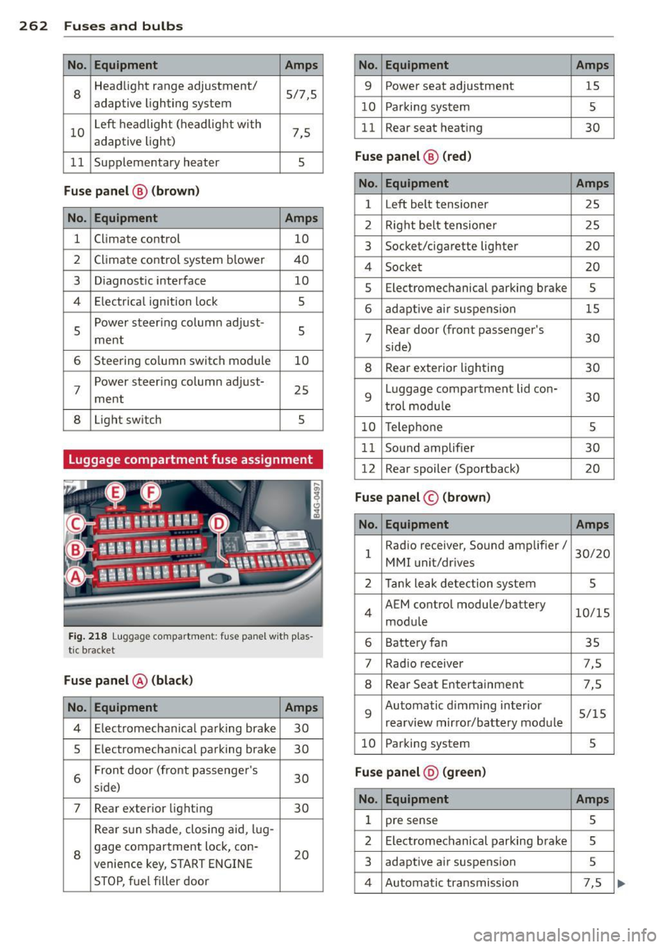
262 Fuses and bulb s
No. Equ ipment Amps
8
Headlight range adjustment/
5/7,S
adaptive lighting system
10 Left headlight
(headlight with
7,5
adaptive light)
11 Supplementary
heater
s
Fuse p ane l@ (b ro w n)
No . Equipment Amps
1 Climate control
10
2 Climate control system blower 40
3 Diagnostic interface
10
4 E lectrical ignition lock
s
s
Power steering column adjust-
s ment
6 Steering column switch module
10
7 Power steering column adjust-
ment
25
8 Light
switch
s
Luggage compartment fuse assignment
Fig. 218 Luggage compartment: fuse panel with plas
tic bracket
Fuse p anel @ (b la ck )
No. Equipment Amps
4 E lectromechanical parking brake 30
s Electromechanical parking brake
30
6 Front door
(front passenger's
30
s ide)
7 Rear exter ior lighting
30
Rear sun shade, closing aid, lug-
8 gage compartment lock, con-
20
venience key, START ENGINE
STOP, fuel filler door
No. Equipment Amps
9 Power seat adjustment
15
10 Parking system
s
11 Rear seat
heating
30
Fuse pan el@ (r e d )
No . Equipment Amps
l Left belt tensioner
25
2 Right belt tensioner 25
3 Socket/cigarette
lighter
20
4 Socket 20
s Electromechanical parking brake s
6 adaptive ai r suspension 15
7 Rear door
(front passenger's
30
side)
8 Rear exterior lighting 30
9 Luggage compartment
lid con-
30
t rol modu le
10 Telephone
s
11 Sound amplifier 30
12 Rear
spoiler (Sportback)
20
Fuse pan el© (brown)
No . Equipment Amps
1 Radio
receiver, Sound amplifier/
30/20
MMI unit/drives
2 Tank leak detection system
s
4 AEM
control module/battery
10/15
module
6 Battery fan 35
7 Rad
io receiver 7,S
8 Rear Seat Entertainment 7,5
9 Automatic d
imming interior
5/15
rearview mirror/battery module
10 Parking system
s
Fuse pan el@ (gre en)
No . Equipment Amps
1 pre sense s
2 Electromechanical parking brake s
3 adaptive
air suspension 5
4 Automatic transmission 7,5