2014 AUDI RS7 SPORTBACK suspension
[x] Cancel search: suspensionPage 117 of 292
r::> & in General information on page 112,
r::>(D in General information on page 113 .
The blue area represents an extens ion of the
vehicle's outline by approximately 16 ft
(5 m) to the rear . The long side of the blue
area should be on the curb . The entire blue
area must fit into the parking space.
• With the veh icle stopped, turn the steering
wheel to the right as far as it w ill go.
• Back in to the park ing space u ntil the b lue
curve
r::> fig . 131 touches the curb r::> & in
General information on page 112,
r::> (D in
General information on page 113 .
Stop the
vehicle.
• With the veh icle stopped , turn the steer ing
whee l to the left as far as it will go .
• Continue to back into the parking space un
t il the vehicle is parked pa rallel to the cu rb
r::> & in General information on page 112,
r::> (D in General information on page 113 .
@ marks the rear bumper. Stop the veh icle,
at the latest, when the red orientation line
@ borders an object. Keep an eye on the
front of your vehicle whi le do ing th is .
Pa rking next to obstacles
If there is an obstacle (s uc h a s a wall) next to
the par king space, position the veh icle so
there is more space o n that s ide. Position the
l ong side of the blue s urface so that there is
sufficient space from the obstacle . The sur
face must not be to uch ing . You will also need
to star t turning the steer ing wheel much ear
lier . The blue curve
r::>fig .131 must not touch
the obstacle and should have sufficient room.
(D Note
Remember to maintain sufficient clear
ance from the curb to avoid damag ing the
wheel rims .
(D Tips
The left or right orientation lines and sur
faces will be displayed, depend ing on the
turn sig na l being used.
P arking systems 115
Peripheral cameras
Introduction
Applies to vehicles: with parking system plus with periph
eral cameras
In add ition to parking system plus
¢
page 111, this parking system conta ins pe
ripheral cameras . Depending on the vehicle
equipment , you are ass isted by vario us views
su ch a s p eriphera l view, corne r views a t the
fron t and rear of the veh icle, and views di rect
ly in front of or behind t he vehicle .
General information
Applies to vehicles: with parking system plus with periph
eral cameras
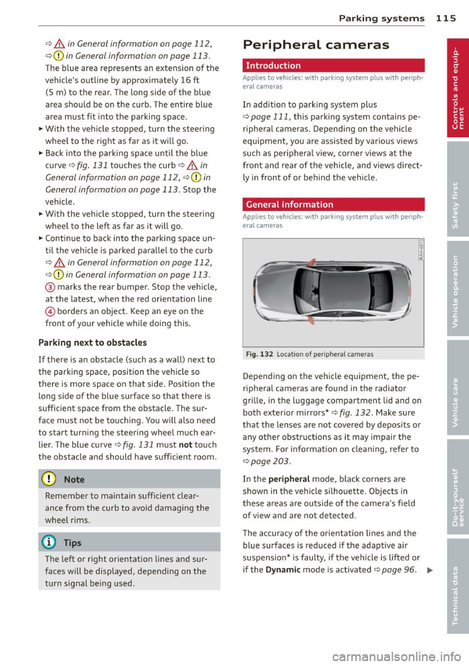
F ig . 1 32 Locat io n of per ip hera l ca meras
Depending on the vehicle equipment, the pe
ripheral cameras are found in the radiator
grille, in the luggage compartment lid and on
both exterior mirrors* ¢
fig. 132. Make su re
that the lenses a re not covered by depos its o r
any other obstr uctions as it may impa ir t he
system. For info rmat io n on clean ing, refe r to
¢ page 203.
In the peripheral mode , b lack corners are
shown in the ve hicle silhouette . Objects in
these a reas a re outside of the came ra's field
of view and are not detec ted .
The accuracy of the orientation lines and the
bl ue surfaces is reduced if the adaptive a ir
suspension* is faulty, if the vehicle is l ifted or
if t he
D ynamic mode is activa ted ¢ page 96. ..,.
Page 161 of 292
experience, informat ion a nd specia l
too ls necessary to perform the work
safely.
- If the veh icle or the circuit interrupter
is scrapped, all applicable safety pre
cautions must be followed.
@ For the sake of the environment
Undep loyed airbag modu les and preten
sioners might be classified as Perchlorate Material - special handling may apply, see
www.dtsc.ca .gov/hazardouswaste/per
chlorate. When the vehicle or parts of the
restraint system including airbag modules
and safety belts w ith pretens ioners are
scrapped, all applicable laws and regula
tions must be observed. Your author ized
Aud i dea ler is familiar with these requi re
ments an d we recommend that yo u have
your dea ler perform this se rvice for you .
Other things that can affect Advanced
Airbag performance
Changing the vehicle's suspension system can
change the way that the Advanced A irbag Sys
tem pe rforms in a crash. For example, us ing
tire -r im combinations not app rove d by Aud i,
l owering the vehicle, changing the stiffness o f
the suspension, incl uding the springs, s uspen
sion struts, shock absorbers etc. can change
the forces that a re measured by the airbag
sensors and sent to the elect ronic control
u ni t. Some suspension changes can, for exam
p le, increase the force levels measured by the
se nsors and make the airbag system deploy in
crashes in wh ich it would not dep loy if the
changes had not been made . Ot her k inds of
change s may reduce the force levels meas
u red by the sensors and prevent the a irbag
from deploying when it shou ld .
The sensors in the safety belt buckle fo r the
d river and front passenger sea t tell the elec
tronic control module if the safety belt is
l atched or not . If the safety belt is be ing used,
the front airbag will dep loy at a slightly high
er rate of vehicle deceleration than if the safe
ty belt is not being used. Therefore, in a pa r-
A irba g sy stem 159
ticular coll is io n, it is possible t hat an airbag
w ill not deploy at a seating position where the
safety belt is be ing used b ut w ill inflate at the
position where the safety belt is not be ing
used . It is important that nothing interfere
with the safety be lt buckles so that the sen
sors can send the cor rect info rmation about
safe ty be lt use to the electronic control un it .
A WARNING .
Changing the vehicle's suspension includ
i ng use of unapp roved tire-r im combin a
tions can cha nge Advanced Airbag per
formance and increase the risk of se rious
personal injury in a crash.
- Never install s uspension componen ts
that do not have the same performance characteristics as the components origi
na lly installed on your vehicle.
- Never use tire -rim combinations that
have not been approved by Audi .
Knee airbags
Description of knee airbags
Applies to vehicles: wit h knee airbags
The knee airbag system can provide supple
mental protection to properly restrained
front seat occupants .
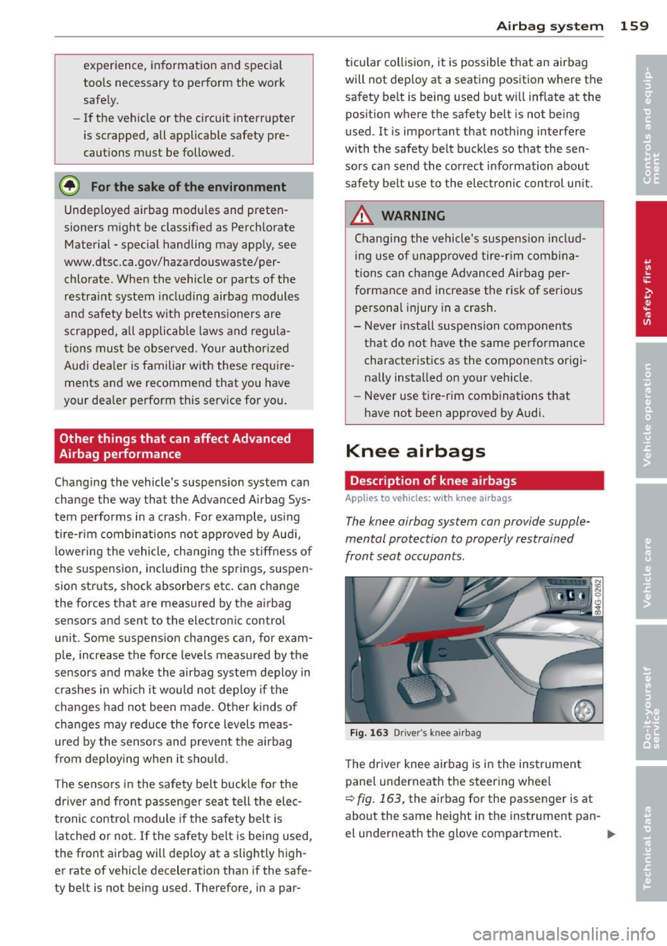
Fig. 1 63 Driver 's k nee airbag
T he driver knee airbag is in the ins trumen t
pane l underneath the steering wheel
r:::> fig. 163, the airbag for t he passenger is at
about the same height in the instrument pan-
el underneath the glove compartment. ..,.
Page 201 of 292
Avoid damaging the
vehicle
When you are driving on poor roads, or over
curbs, steep ramps, etc., make certain that
low-lying parts such as spoilers and exhaust
system parts do not bottom out and get dam
aged.
T his is especially true for vehicles with low
slung chassis (sports chassis) * and fully load
ed veh icles .
Driving through water
on roads
Note the following to avoid vehicle damage
when driving through water, for example on
flooded roads:
- T he water must not be any h igher than the
bottom of the veh icle body.
- Do not d rive faster than wa lking speed.
..&, WARNING
After driving through wate r, m ud, slush,
etc., the brakes may be slow to take effect
because o f wet brake rotors and pads . Dry
the brakes first by braking carefully to re
store the full braking effect.
(D Note
- Vehicle components such as the eng ine,
transmission, suspension or e lectrical
system can be severely damaged by driv ing through water.
- Check the depth o f the water before driv
ing through it.
- Do not s top the veh icle, drive in reverse
or switc h the engine off when driving
through water.
- Keep in mind that oncoming vehicles may create waves that raise the water
level and make it too deep for your vehi
cle to drive through safely.
- Avoid driving thro ugh sa lt water because
it can ca use corrosion.
-
Dri vin g and en vironm ent 199
Warming up and
cooling down
By carefully warming up and cooling down
your vehicle, you can help ensure that it is not
overstressed unnecessar ily during sporty dr iv
ing.
When warming up, the vehicle is dr iven at a
maximum engine speed of 6000 RPM in order
to raise the engine o il temperature to a mini
mum of 140
°F (60 °() . The t ires a lso on ly
reach the ir full road holdi ng capabi lity once
they have warmed up.
The cooli ng fan can cont inue to run in your ve
hicle after the engine is switched off . Howev
er, driving the veh icle to coo l it down is pa rti c
ul arly important. Dur ing spo rty driving , the
engine and b rakes, the exhaust system, and
the transmission a ll become extremely hot.
Before you park the vehicle, you should drive
it for a few miles/kilometers at light load in
the low rpm range to allow it to cool down .
Catalytic converter
App lies to vehicles: wi th gaso line e ngi ne
It is very important that your emission con
trol system (catalytic converter) is function
ing properly to ensure that your vehicle is run
ning in an environmentally sound manner.
"' Always use lead-free gasoline c:> page 208,
Fuel supply .
"' Never run the tank down all the way to emp
ty.
"' Never put too much mo to r o il in yo ur eng ine
c:> page 218, Adding engine oil "t:::r..
"' Never try to push -or tow -start you r vehicle .
T he catalytic co nve rter is an efficient "clean
u p" dev ice bui lt into t he exhaus t system of
the ve hicle . The cata lytic converter bu rns
many of the pollutants in the exha ust gas be
fore they are re leased into the atmosphere.
T he exclus ive use of unleaded fuel is c ritical ly
i mportant for the life of the catalyt ic convert -
er and proper functioning of the engine .
Iii>
•
•
Page 240 of 292
238 Tires and wheels
symbols) indicate the positions of the tread
wear indicators. Worn tires must be replaced. Different figures may apply in other countries
c::> & .
Tire pressure
Incorrect tire p ressure causes premature wear
and can cause sudden tire blow-out. For this
reason, tire pressure must be checked at least
once a month
c::> page 234.
Driving style
Driving fast around curves, heavy acceleration
and hard braking increase tire wear.
Rotating tires for more even wear
For all four tir es on your vehicle to have the
same se rv ice life, we recommend that the
front and rear tires are rotated according to
the tire manufacturer's suggested tire rota
tion intervals. Please remember the follow
ing:
- T ire rotation inte rva ls may differ from the
vehicle serv ice intervals outlined in your
Warranty
& Maintenance booklet.
- T he longer one tire is used in one location
on the vehicle, the more it wears at certa in
points; therefore, we recommend that you
follow the tire manufacturer's suggested
tire rotation intervals.
- Vehicles with front-wheel drive experience
more tread wear on the front whee ls com
pared to all-whee l drive (quattro).
- Please rotate ti res as shown
c::> fig. 198.
-Extra care must be taken when rotating di-
rection-specific tires
c::> page 2 59.
Wheel balancing
The wheels on new vehicles are balanced .
Ho wever, various situations during everyday
driving can cause them to become unbal
anced, resu lting in vibrations you can usually
feel through the steering wheel.
Unba lanced wheels must be rebalanced to
avoid excessive wea r on steering, suspension
and tires . A wheel must a lso be rebalanced
when a new tire is installed. Incorrect wheel alignment
Incorrect
wheel alignment can cause exces
sive tire wear, impairing the safety of the vehi
cle. If tires show excessive wear, have the
wheel alignment checked by an a uthorized
Audi dealer or qualified workshop.
All-wheel drive
Vehicles with quattro must always have tires
of the same size, construction and tread type.
For details see
c::>page 195.
_8 WARNING
-Sudden tire fa ilure can lead to loss of con-
trol, a crash and serious personal injury!
- Never drive a vehicle when the tread on
any tire is worn down to the wear indica
tors.
- Worn t ires are a safety hazard, they do
not grip well on wet roads and increase
your risk of "hydroplaning" and loss of
control.
- Always keep chemicals that can cause
tire damage, such as grease, o il, gasoline
and brake fluid away from tires.
- Tires age even if they are not being used
and can fai l suddenly, especially at high
speeds. Tires that are more than 6 yea rs
old can only be used in an emergency
and then w ith specia l care and at lower
speeds.
- Never mount used tires on your veh icle if
you are not sure of their "previous histo
ry." O ld used tires may have been dam
aged even though the damage cannot be
seen that can lead to sudden tire fai lure
and loss of vehicle control.
Page 246 of 292
24 4 T ire s and wheel s
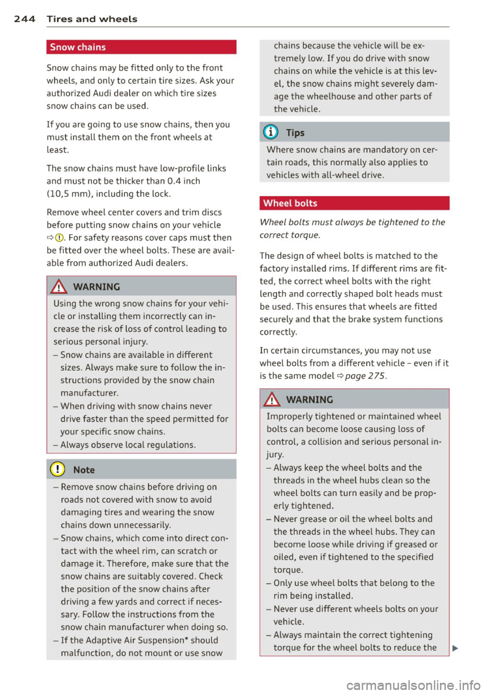
Snow chains
Snow chains may be fitted on ly to the front
wheels, and only to certain tire sizes. Ask your
authorized Audi dealer on whic h tire sizes
snow chains can be used.
I f you are going to use snow chains , then you
must install them on the front wheels at
l east.
The snow chains must have low-profile links
and must not be thicker than 0.4 inch (10 ,5 mm), including the lock .
Remove wheel center covers and tr im discs
before putting snow cha ins on your vehicle
c:;, Q) _ For safety reasons cover caps must the n
be fitted over the whee l bolts. These are ava il
ab le from authorized Audi dea lers.
A WARNING
Using the wrong snow chains for yo ur vehi
cle or installing them incorrectly can in
crease the risk of loss of control leading to
ser ious personal inj ury.
- Snow chains are ava ilable in different
sizes. Always make sure to follow the in
struct ions provided by the snow chain
manufacturer .
- When driving w ith snow chains never
dr ive faster than the speed permitted for
your specific snow cha ins.
- Always observe local regulat ions .
([) Note
-Remove snow cha ins before driving on
roads not covered with snow to avoid
damaging t ires and wear ing the snow
chains down unnecessar ily.
- Snow chains, wh ich come into d irect con
tact with the wheel rim, can scratch or
damage it . Therefore, make sure that the
snow chains are suitab ly covered . Check
the position of the snow chains after
driving a few yards and correct if neces
sa ry. Follow the i nstructions from the
snow cha in manufacture r when doing so.
- If the Adaptive Air Suspension* should
malfunction, do no t mo unt or use snow chains because the vehicle will be ex
treme ly low. If you do drive with snow
chains on while the vehicle is at this lev
el, the snow cha ins might severely dam
age the whee lhouse and other parts of
the vehicle .
(D Tips
Where snow chains are mandatory on cer
tain roads, th is normally a lso applies to
vehicles with all-wheel drive.
Wheel bolts
Wheel bol ts mus t alway s be tightened to the
correc t torque.
The design of wheel bolts is matched to the
factory installed rims . If different r ims are fit
ted, the correct wheel bol ts with the righ t
length and correct ly shaped bolt heads must
be used . T his ensures that wheels are fitted
securely and that the b rake system functions
co rrect ly.
In certa in circumstances, you may not use
wheel bolts from a different veh icle -even if it
is the same model
c:;, page 275 .
A WARNING
Imp rope rly t ightened or ma inta ined wheel
bo lts can become loose c ausing loss of
control, a col lision and serio us pe rsonal i n
jury .
- Always keep the wheel bo lts and the
threads in the wheel hubs clean so the
wheel bo lts can turn easily and be prop
erly tightened.
- Never g rease or oil the wheel bolts and
the threads in t he wheel hubs . They can
become loose while driv ing if greased or
oiled, even if t ightened to the specified
torque.
- On ly use wheel bolts that belong to the
rim being installed .
- Never use different wheels bolts on yo ur
veh icle.
- Always maintain the correct t ightening
torque for the whee l bolts to reduce the
Page 256 of 292
254 What do I do now?
After a tire repa ir, have the sealant bottle
rep laced at a dealership. This restores full
functionality to the Tire Mob ility System.
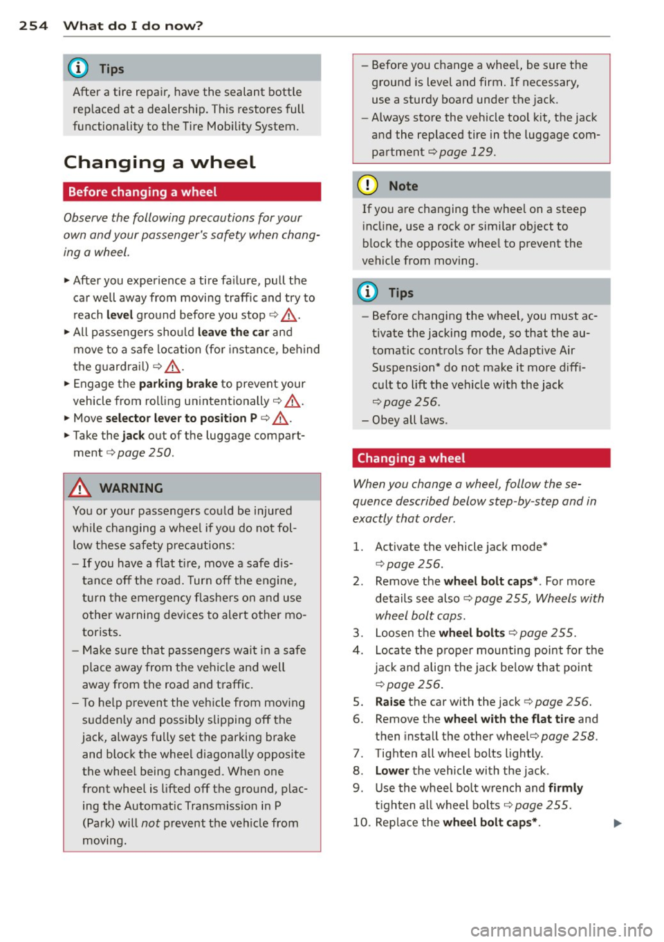
Changing a wheel
Before changing a wheel
Observe the following precautions for your
own and your passenger's safety when chang
ing a wheel .
• After you experience a tire fa ilure, pull the
car well away from moving traffic and try to
reach
level g ro und before you stop¢ /.1..
• All passengers sho uld le ave the car a nd
move to a sa fe loca tion (fo r instance, beh ind
t h e guardrai l) ¢
/.1. .
• Engage the pa rking b rake to prevent your
vehicle from ro lling unintentionally ¢
/.1..
• Move selector leve r to position P ¢ &_ .
• Take the jack out of the luggage compart
ment
¢ page 250.
A WARNING
You or your passe ngers cou ld be injured
w hile c hanging a whee l if you do not fol
low t hese safety p re cau tions:
-If you have a flat t ire, move a safe dis
tan ce off the road. Tur n off the e ng in e,
tu rn the e mergen cy fla shers o n and use
other wa rning dev ices to alert o ther mo
torists.
- M ake su re th at passengers wai t in a safe
place away from the ve hicl e an d well
away from the road and traff ic.
- T o help p revent the veh icle from mov ing
s u dden ly and possibly slipping off the
jack, a lways fully set the parking bra ke
and bloc k the whee l diagona lly opp osite
the whee l being cha nged. When one
front whee l is lifted off the gro und, plac
ing the A utomat ic Transmiss io n in P
(Pa rk) will
not pre vent the vehicle from
moving. -
Before you change a wheel, be s ure t he
ground is level and firm. If necessary,
use a sturdy board under the jack.
- Always store the vehicle tool kit, the jack
and the rep laced tire in t he luggage com
partment
¢page 129.
(D Note
If you are changing the whee l on a steep
i ncl ine, use a roc k or similar object to
block the opposite whee l to prevent the
vehicle from moving.
(D Tips
- Before changing the wheel, you must ac
tivate the jacking mode, so that t he au
tomatic cont rols for the Adaptive Air
Suspension* do not ma ke it mo re d iff i
cult to lift the veh icle w it h the jack
¢page 256.
- Obey all laws.
Changing a wheel
When you change a wheel , follow these
quence described below step-by-step and in
exactly that order .
l. Activate the vehicle jack mode*
¢ page 256.
2. Remove the wheel bolt caps* . For more
details see also ¢
page 255, Wheels with
wheel bolt caps.
3. Loosen the wheel bolt s ¢page 255.
4. Loc ate the p roper moun ting point fo r the
j ack an d align the jack be low that poin t
¢page 256.
5. Raise the car with the jack¢ page 256.
6. Remove the wheel with the flat tire and
then insta ll the other whee[¢
page 258.
7. Tighte n all whee l bolts lightly .
8.
Lower the vehicle wi th the jack .
9 . Use the wheel bolt w rench and
firmly
t ig ht en al l w heel bo lt s¢ page 255.
10. Re place the wheel bolt caps* .
Page 263 of 292

No. Equ ipment Amps
4 Suspension control system sen-s sor
s
E
lectronic Stabilization Cont rol
s (ESC) module
6 Climate control
5
7 Adaptive cruise control 10
8
Airbag control module, front
5
passenger's seat sensor system
9 Gateway 5
Homelink (garage doo r opener),
10 night vis ion system cont ro l 5
module
11 Image
processing (active lane
10
ass ist, adaptive cruise control)
12 Dynamic steering 5
13 Terminal 15 in
the instrument
15
panel
14 Terminal 15
in the luggage com-
partment 30
15 Terminal 15
(engine)
15
16 Starter 40
Fu se pa nel ® (b rown )
No . Equipment Amps
1 Gateway
5
2 C limate control 10
3 E
lectronic Stabili zation Contro l
10
(ESC) module
4 Fron
t door (driver 's side)
30
s
Power seat adjustment (driver's
7,5
seat)
6 Dynam
ic steering
35
7 Sunroof 20
8
Rear door control module (driv-
15
er 's side)
9 Lumbar support (
Front passen-
s ger seat)
10 Tire pressure
monitoring system
5
11 Su
nroof, rear spoi ler (Sportba ck)
20
12 Driver
door control module
15
Fuse s and bulb s 261
Fuse pan el© (r e d )
No . Equipment
2 Fuel pump
3 Brake light sensor/brake pedal
sensor system
AdBlue control module (Diesel)/
4 Engine acoust ics
5 Left rear door cont rol modu le
6 Power seat adjustment
(pas-
senge r's seat)
7 Horn
8 Windshield wiper motor
9 Light/rain sensor, heater
for vid-
eo camera in windscreen
10 L umba r support (driver seat)
1 1 Front
passenger door control
modu le
12 Right rea r door cont rol modu le
Front passenger side cockpit fuse
assignment Amp
s
25
5/5
5/7,S 30
7,5 15
30
s
5
15
15
F ig . 217 Front passenger side cockpit: fuse pa nel w it h
plast ic brac ket
Fuse panel @ (bla ck)
No . Equipment Amps
1 Head-up
Display
5
2 MMI Display 5
3 CO/DVD changer
5
4 MMI unit/drives 7,5
5 Chip
card reader (not in all coun-
5
tries)
6 Instrument
cluster
5
7 Steering column switch module 5 ...
Page 264 of 292
262 Fuses and bulb s
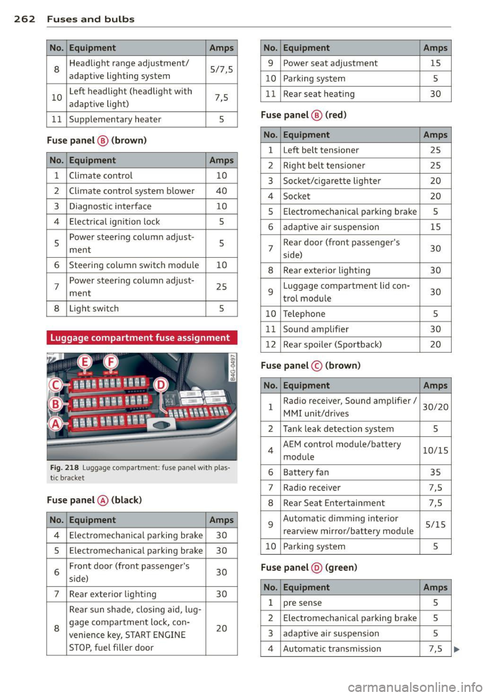
No. Equ ipment Amps
8
Headlight range adjustment/
5/7,S
adaptive lighting system
10 Left headlight
(headlight with
7,5
adaptive light)
11 Supplementary
heater
s
Fuse p ane l@ (b ro w n)
No . Equipment Amps
1 Climate control
10
2 Climate control system blower 40
3 Diagnostic interface
10
4 E lectrical ignition lock
s
s
Power steering column adjust-
s ment
6 Steering column switch module
10
7 Power steering column adjust-
ment
25
8 Light
switch
s
Luggage compartment fuse assignment
Fig. 218 Luggage compartment: fuse panel with plas
tic bracket
Fuse p anel @ (b la ck )
No. Equipment Amps
4 E lectromechanical parking brake 30
s Electromechanical parking brake
30
6 Front door
(front passenger's
30
s ide)
7 Rear exter ior lighting
30
Rear sun shade, closing aid, lug-
8 gage compartment lock, con-
20
venience key, START ENGINE
STOP, fuel filler door
No. Equipment Amps
9 Power seat adjustment
15
10 Parking system
s
11 Rear seat
heating
30
Fuse pan el@ (r e d )
No . Equipment Amps
l Left belt tensioner
25
2 Right belt tensioner 25
3 Socket/cigarette
lighter
20
4 Socket 20
s Electromechanical parking brake s
6 adaptive ai r suspension 15
7 Rear door
(front passenger's
30
side)
8 Rear exterior lighting 30
9 Luggage compartment
lid con-
30
t rol modu le
10 Telephone
s
11 Sound amplifier 30
12 Rear
spoiler (Sportback)
20
Fuse pan el© (brown)
No . Equipment Amps
1 Radio
receiver, Sound amplifier/
30/20
MMI unit/drives
2 Tank leak detection system
s
4 AEM
control module/battery
10/15
module
6 Battery fan 35
7 Rad
io receiver 7,S
8 Rear Seat Entertainment 7,5
9 Automatic d
imming interior
5/15
rearview mirror/battery module
10 Parking system
s
Fuse pan el@ (gre en)
No . Equipment Amps
1 pre sense s
2 Electromechanical parking brake s
3 adaptive
air suspension 5
4 Automatic transmission 7,5