2014 AUDI RS7 SPORTBACK parking brake
[x] Cancel search: parking brakePage 108 of 292
106 Automatic Transmission
lever is left in N (Neutral) for more than ap
proximately 2 second, without the brake ped
a l being pressed .
Release button
The release button on the selector lever pre
vents the lever from being accidentally shifted
into certain positions. Depending on the direc
tion of the shift, the se lector lever locks at d if
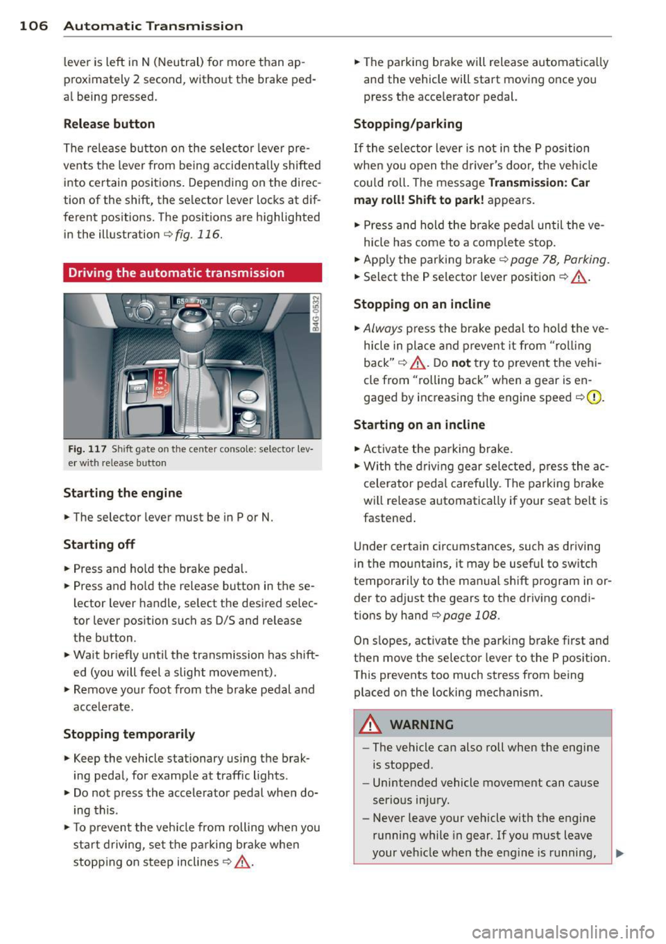
ferent positions. The positions are highlighted in the illustration
c:;, fig. 116.
Driving the automatic transmission
Fig. 117 Sh ift gate on the center conso le: selector lev
er w ith release button
Starting the engine
,.. The selector lever must be in P or N.
Starting off
,.. Press and ho ld the brake pedal.
,.. Press and ho ld the release button in these
lector lever handle, se lect the desired se lec
tor lever position such as 0/5 and release
the button .
,.. Wait briefly until the transmission has shift
ed (you will feel a slight movement) .
,.. Remove your foot from the brake pedal and
acce le rate.
Stopping temporarily
,.. Keep the vehicle stationary us ing the brak
ing peda l, for example at traffic lights.
,.. Do not press the accelerator pedal when do
ing this .
,.. To prevent the veh icle from rolling when you
sta rt driving, set the parking brake whe n
stopping on steep inclines
c:;, _& .
,.. The parking brake will release automatica lly
and the vehicle will start moving once you
press the acce lerator pedal.
Stopping/parking
If the sele ctor lever is not in the P position
whe n you open t he driver's door, the veh icle
could roll. The message
Transmission: Car
may roll! Shift to park!
appears.
,.. Press and hold the brake pedal until the ve-
hicle has come to a complete stop.
,.. App ly the parking brake
c::> page 78, Parking.
,.. Select the P selector lever position c:;, _& .
Stopping on an incline
,.. Always press the brake pedal to hold the ve
hicle in place and prevent it from "rol ling
back"
c:;, _& . Do not try to prevent the vehi
cle from "rolling back" when a gear is en
gaged by increasing the engine speed
c::>(D .
Starting on an incline
,.. Activate the parking brake.
,.. With the driving gear selected, press the ac
celerator pedal carefully. The parking brake
will release automatically if your seat belt is
fastened .
Under certain circumstances, such as driving
in the mounta ins, it may be usefu l to sw itch
temporarily to the manual shift program in or
der to adj ust the gears to the driving condi
t ions by hand
c::>page 108 .
On slopes, activate the parking brake first and
then move the selector lever to the P position.
This prevents too much stress from being placed on the locking mechanism.
A WARNING
-
- The vehicle can also roll when the engine
is stopped .
- Unintended vehicle movement can cause
serious injury.
- Never leave your vehicle with the engine
running while in gear . If you must leave
your vehicle when the engine is running,
Page 109 of 292
activate the parking brake and move the
selector lever to P.
- Power is sti ll transmitted to the wheels
when the engine is running at idle. To
prevent the vehicle from "creeping", you
must keep your foot on the brake when
the engine is running and the selector
lever is in D/S or R or "tiptronic" mode is
selected.
- Do not press the accelerator pedal when changing the selector lever pos ition
wh ile the vehicle is stat ionary and the
engine is running .
- Never shift into
R or P wh ile driving .
- Before driv ing down a steep slope, re -
duce your speed and shift into a lower
gear with "tiptronic".
- Do not ride the brakes or press the brake
peda l too often or too long when dr iv ing
down a hill. Constant braking causes the brakes to ove rheat and substant ially re
duces braking performance, increases
braking distance or ca uses comp lete fail
vre of the brake system .
- To prevent the vehicle from rolling back
when stopping on inclines, always hold it in place with the brake pedal or parking
brake.
- Never hold the vehic le on an incline with
a slipping clutch . The clutch opens auto
matically when it becomes too hot from
the overload. An indicator lamp
[O] illu
minates and a dr iver message appears
~ page 108 when the clutch is overload
ed .
- If the engine must remain running, never have any driv ing position engaged when
check ing under the hood.
M ake sure the
selector lever has secure ly engaged and
is locked in P with the parking bra ke set
¢ page 213 . Otherwise, any increase in
engine speed may set the vehicle in mo
t ion, even with the park ing brake ap
plied.
(D Note
- When stopping on an incline, do not try to hold the vehicle in place by pressing
Aut omat ic Tr ans missio n 107
the acce lerator pedal while a d riving gea r
is se lected. This can cause the transmis
sion to ove rheat and can damage it. Acti
vate the parking brake or press the brake peda l to prevent the vehicle from rolling .
- Allowing the vehicle to roll when the en gine is stopped and the selector lever is
in N will damage the transmission be
cause
i t is not lubricated under those cir
cumstances.
(D Tips
For safety reasons, the parking brake is re
leased automatically o nly when the driv
e r's safety belt is engaged in the buckle .
, Hill descent control
The hill descent control system assists the
driver when driving down declines .
Hill descent contro l is activa ted when these
lector lever is in D/S and you press the brake
pedal. The transmission automatically selects
a gear that is suitable for the incline . H ill de
scent cont ro l t ries to ma inta in the speed ach
ieved a t the t ime of braking, with in phys ica l
and tec hni cal lim itations. If may st ill be nec
essary to adj ust the speed with the brakes .
Hill descent contro l sw itches off once the de
cl in e leve ls out or yo u press the acce le rato r
pedal.
On vehicles with the cruise cont ro l system*
¢ page 79 , hill descent control is also activat
ed whe n the speed is set.
&_ WARNING
-
Hill descent co nt rol cannot overcome
physical lim itations, so it may not be ab le
to maintain a constant speed under a ll
conditions. A lways be ready to apply the
brakes .
Page 123 of 292

Homelink
Universal remote
control
General information
Applies to vehicles: with Home link unive rsal remote con
tro l
The Homelink universal remote control can
be programmed with hand-held transmitters
from existing equipment
With Home link, you can control devices such
as the garage door, security systems, house
lights, etc. comfortably from the inside of you
vehicle.
Homelink makes it possible for you to replace
three different remote controls from devices
in your home with one universal remote . This
feature works for most garage door and exte rior door motor signals. Programmi ng the in
d iv idual remote control for your remote con
trol takes place near the center of the radiator
grille. There is a control module attached at
this location .
A one-t ime programming of the sensor must
be performed before you are able to use sys
tems with Homelink.
A WARNING , .,.
- Never use the Homelink transmitter
with any garage door opener that does
have not the safety stop and reverse fea
ture as required by federal safety stand
ards . Th is includes any garage door open
er model manufactured before April 1, 1982.
- A garage door opener which cannot de
tect an object, signaling the door to stop
and reverse does not meet current feder
al safety standards . Us ing a garage door
opener without these features increases
risk of serious injury or death.
- For safety reasons
never release the
parking brake or start the engine while
anyone is standing in front of the vehicle .
- A garage door or an estate gate may sometimes be set in motion when the
H ome link 121
Homelink remote control is being pro
grammed. If the device is repeatedly ac
tivated, this can overstrain motor and
damage its electrical components -an
overheated motor is a fire hazard!
- To avoid possible injuries or property
damage, please always make absolutely
certa in that no persons or objects are lo
cated in the range of motion of any
equipment being ope rated.
(D Tips
- If you would like additional information
on the Home link Universal Transce iver
I
Homel ink compatib le products, or to
purchase other accessories such as the
Homelink Lighting Package, please con
tact Homelink at 1-800-355 -3515 or on
the Internet at www. homelink.com.
- For Declaration of Comp liance to United
States FCC and Ind ustry Canada reg ula
tions~
page 2 76.
- For security reasons, we recommend that
you clear the programmed buttons be
fore selling the vehicle .
Operation
Applies to vehicles: with Homelink
Fig. 144 Headliner : cont rols
Req uirement: The bu ttons must be program
med
~ page 122.
.,. To open the garage door, press the program
med button . The LED @ will light up or
flash.
... To close the garage door , press the button
again .
II>
Page 215 of 292
Checking and filling Engine hood
Releasing the engine hood
The engine hood is released from inside the
vehicle .
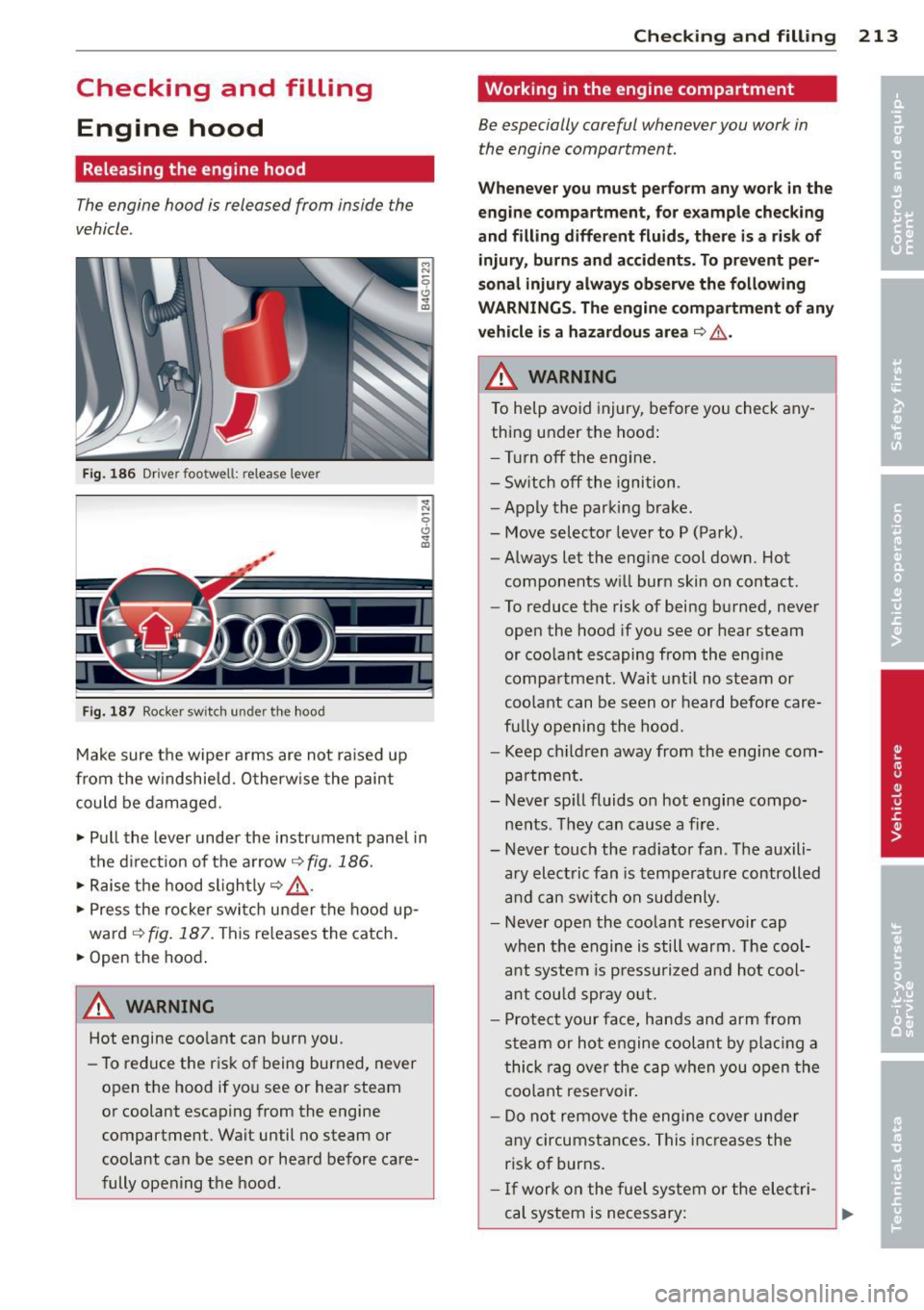
Fig. 186 Dr iver footwell: release lever
Fig. 187 Rocker switch under the hood
Make sure the wiper arms are not raised up
from the w indshield. Otherw ise the paint
could be damaged.
.. Pull the lever under the instrument panel in
the d irect ion of the arrow~
fig. 186.
.. Raise the hood slightly~ &-
.. Press the rocker switch under the hood up
ward
~ fig. 187. This re leases the catch .
.. Open the hood .
A WARNING
Hot engine coo lant can burn you.
- To reduce the r isk of being burned, never
open the hood if you see or hear steam
or coolant escaping from the engine
compartment . Wait until no steam or
coolant can be seen or heard before care
fully opening the hood.
Checkin g and fillin g 213
Working in the engine compartment
Be especially careful whenever you work in
the engine compartment.
W hen ev er y ou must p erform an y wor k in the
en gine com pa rtm ent , for e xample checking
a nd filling diff ere nt fluid s, th ere is a risk of
inju ry, burn s and accid ents. To pr eve nt p er
so nal inju ry always observ e the foll owing
W ARNING S. The engin e compartm ent of any
v e hicle i s a haza rdou s area
~ ,& .
h WARNING
To help avoid injury, before yo u check any
thing under the hood:
- Turn off the engine.
- Sw itch off the ignition.
- Apply the parking brake.
- Move selector leve r to P (Park).
- Always let the engine cool down. Hot
components w ill burn skin on contact .
- To reduce the risk of being burned, never
open the hood if you see or hear steam
or coo lant escaping from the engine
compa rtment. Wait unt il no steam or
coolant can be seen or heard before care
fu lly opening the hood.
- Keep ch ildren away from the engine com
pa rtment.
- Never sp ill fluids on hot engine compo
nents . They can cause a fire .
- Never touch the rad iator fan. The auxili
ary electric fan is temperat ure controlled
and can switch on suddenly .
- Never open the coolant reservoir cap
when the engine is still warm. The cool
ant system is p ressu rized and hot cool
a nt cou ld spray o ut.
- Protect your face, hands and arm from
steam or hot engine coolant by plac ing a
thick rag ove r the cap when you open the
coo lant rese rvoir.
- Do not remove the engine cover under
any circumstances. This inc reases the
ris k of burns.
- If work on the fue l system o r the elec tri
cal system is necessary:
Page 254 of 292
252 What do I do now?
(D Note
Do not use commerc ia lly available tire
sealants . The electrical components of the
tire pressure mon itoring system will no
longer work properly.
@ For the sake of the environment
Used sealant bottles can be dropped off at
a recycl ing facility.
@ Tips
- If sealant has run out, allow it to dry.
Then you can peel it off.
- Have the tire sealant replaced every 4
years at a dea lership.
Preliminary steps
Some preliminary steps ore necessary for tire
repair.
.,. If you have a fla t t ire, park the veh icle as far
as possible from moving traffic.
.,. Apply the
parking brake firmly .
.,. Move the
selector lever to the P position .
.,. Check whether a repair using the Tire Mobili
ty System is possible Q page 251, General
and safety pointers .
.,. Have all passengers leave the vehicle and
stay away from the danger zone
q ,& .
.,. Take the s ealant bottle and the electric air
pump
from the luggage compartment un
der the floor.
.,. Remove the "max . SO mph" (80 km/h) stick
er from the sealant bottle and aff ix it to the
instrument cluster in the driver's view .
A WARNING
-Turn the hazard flashers on and set up
the warning triangle* if you have a flat
tire in moving traffic. In this way you pro
tect you rs elf and other road users .
- Make sure that all passengers are in a
safe place, out of the danger zone (for
example, behind a guard ra il).
-
(D Note
Particular care is necessary if you are mak
ing a tire repa ir on a steep incl ine.
@ Tips
Obey all laws.
Making a tire repair
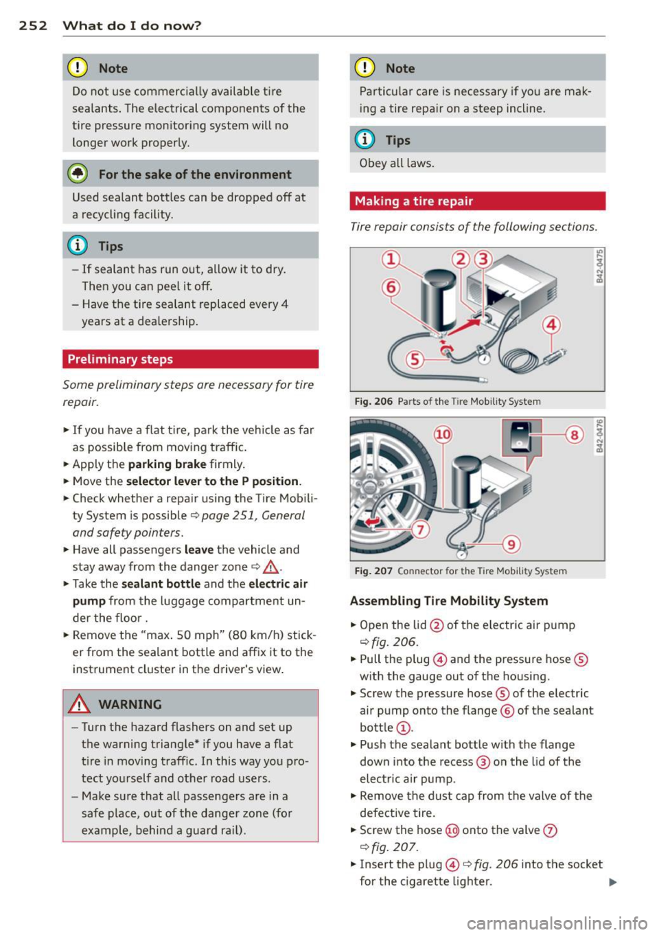
Tire repair consists of the following sections.
Fig. 206 Parts of t he Tire Mob ility System
Fig. 207 Co nn ector for the Tire Mobility Sys tem
Assembling Tire Mobility System
.,. Open the lid @of the electric air pump
qfig. 206.
.,. Pull the plug @and the pressure hose ®
with the gauge out of the housing .
.,. Screw the pressure hose ® of the electric
air pump onto the flange ® of the sealant
bottle @.
.,. Push the sealant bottle w ith the flange
down into the recess@ on the lid of the
electric air pump .
.,. Remove the d ust cap from the valve of the
defective tire .
.,. Screw the hose@) onto the valve
(J)
qfig. 207 .
.,. Insert the plug@¢ fig. 206 into the socket
for the cigarette lighter.
IJJ,
Page 258 of 292
256 What do I do now?
Loosening
.,. Slide the wheel wrench onto the wheel bolt
as far as it will go.
.,. Take tight hold of the
end of the wrench
handle and turn the wheel bolts
counter
clockwise
about one single turn in the direc
t ion of arrow
c:;, fig. 209.
Tightening
.,. Slide the wheel wrench onto the wheel bolt
as far as it will go .
.,. Take tight hold of the
end of the wrench
hand le and turn each wheel bolt
clockwise
until it is seated.
_& WARNING
- Do not use force or hurry when changing
a wheel -you can cause the vehicle to slip
off the jack and cause serious personal injuries.
- Do not loosen the wheel bolts more than
one turn
before you raise the vehicle with
the jack. -You risk an injury.
@ Tips
- Never use the hexagonal socket in the
handle of the screwdriver to loosen or
tighten the wheel bolts.
- If a wheel bolt is very tight, you may find
it easier to loosen by carefully pushing
down on the end of the wheel bolt
wrench with
one foot only. As you do so,
hold on to the car to keep your balance
and take care not to slip.
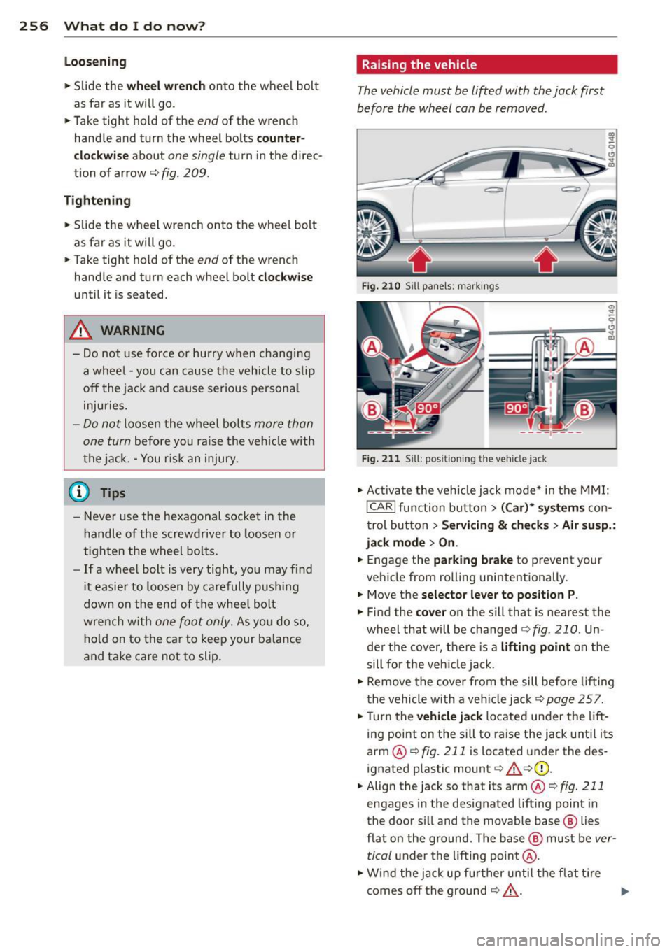
Ra ising the vehicle
The vehicle must be lifted with the jack first
before the wheel can be removed .
Fig. 210 Sill pane ls : markings
; q
--~~~~~-~
Fig. 211 Sill: posit ioning the Ve hicle jack
.,. Activate the vehicle jack mode* in the MMI:
!CARI function button> (Car)* systems con
trol button>
Servicing & checks> Air susp.:
jack mode
> On.
.,. Engage the parking brake to prevent your
vehicle from rolling unintentionally.
.,. Move the
selector lever to position P .
.,. Find the cover on the sill that is nearest the
wheel that will be changed
c:;, fig. 210 . Un
der the cover, there is a
lifting point on the
sill for the vehicle jack .
.,. Remove the cover from the sill before lifting
the vehicle with a vehicle jack
c:;, page 257 .
.,. Turn the vehicle jack located under the lift
ing point on the sill to raise the jack until its
arm @
c:;, fig. 211 is located under the des
ignated plastic mount
c:;, &c:;,(I) ,
.,. Align the jack so that its arm @ c:;, fig. 211
engages in the designated lifting point in
the door s ill and the movable base @ lies
flat on the ground . The base @ must be
ver
tical
under the lifting point @ .
.,. Wind the jack up further until the flat tire
comes off the ground
c:;, & . ..,.
Page 262 of 292
260 Fuses and bulbs
Fuses and bulbs
Fuses
Replacing fuses
Fuses that have blown will have metal strips
that have burned through.
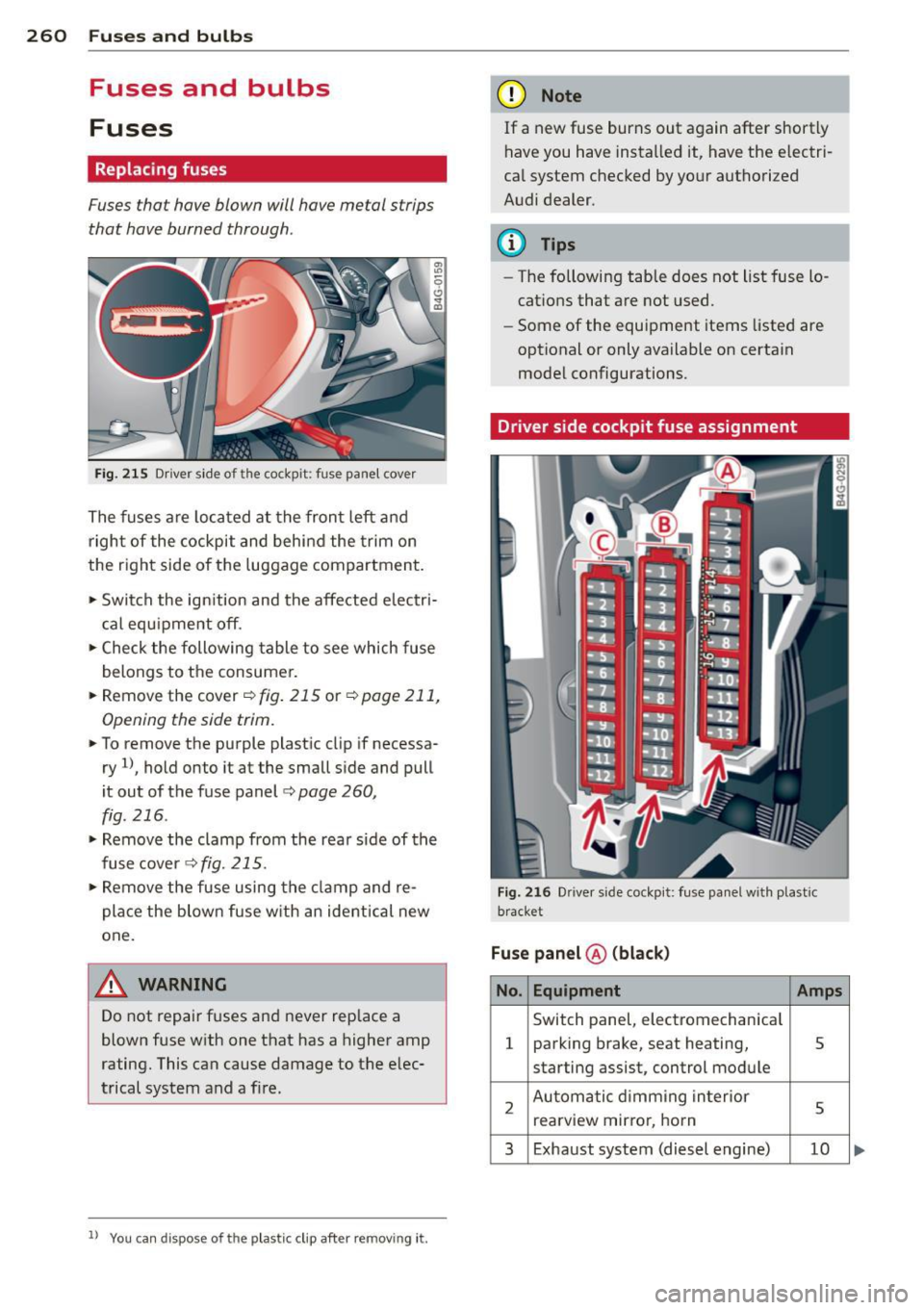
Fig. 215 Driver side of the cockpit: fuse panel cover
The fuses are located at the front left and
right of the cockpit and behind the trim on
the right side of the luggage compartment.
• Switch the ign ition and the affected electri
cal equ ipment off.
• Check the following table to see which fuse
belongs to the consumer.
• Remove the cover ¢
fig. 215 or¢ page 211,
Opening the side trim.
• To remove the purple plastic clip if necessa
ry
ll, hold onto it at the small side and pull
it out of the fuse panel
c:> page 260,
fig. 216 .
• Remove the clamp from the rear s ide of the
fusecover <>fig.
215.
• Remove the fuse using the clamp and re
pla ce the blown fuse w ith an ident ical new
one.
A WARNING
Do not repair fuses and never replace a
blown fuse with one that has a higher amp
rating. This can cause damage to the elec
trical system and a fire.
ll You can dis pose of the plastic clip after re moving it.
(D Note
If a new fuse burns out again after shortly
have you have installed it, have the electri
cal system checked by your authorized
Audi dealer.
(D Tips
-The following table does not list fuse lo
cations that are not used.
- Some of the equipment items listed are
optional or only available on certain
model configurations.
Driver side cockpit fuse assignment
Fig. 216 Dr ive r side cockpit: fuse panel with plastic
bracket
Fuse panel ® (black)
No. Equipment Amps
Switch panel, electromechanical
1 parking brake, seat heating, 5
starting assist, control module
2 Automatic dimming interior
5 rearview mirro r, horn
3 Exhaust system (diesel engine) 10
Page 264 of 292
262 Fuses and bulb s
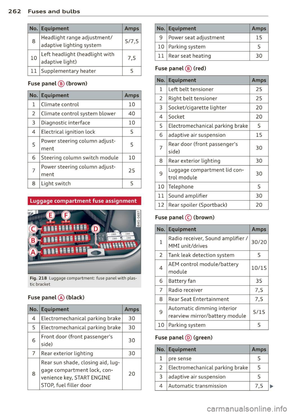
No. Equ ipment Amps
8
Headlight range adjustment/
5/7,S
adaptive lighting system
10 Left headlight
(headlight with
7,5
adaptive light)
11 Supplementary
heater
s
Fuse p ane l@ (b ro w n)
No . Equipment Amps
1 Climate control
10
2 Climate control system blower 40
3 Diagnostic interface
10
4 E lectrical ignition lock
s
s
Power steering column adjust-
s ment
6 Steering column switch module
10
7 Power steering column adjust-
ment
25
8 Light
switch
s
Luggage compartment fuse assignment
Fig. 218 Luggage compartment: fuse panel with plas
tic bracket
Fuse p anel @ (b la ck )
No. Equipment Amps
4 E lectromechanical parking brake 30
s Electromechanical parking brake
30
6 Front door
(front passenger's
30
s ide)
7 Rear exter ior lighting
30
Rear sun shade, closing aid, lug-
8 gage compartment lock, con-
20
venience key, START ENGINE
STOP, fuel filler door
No. Equipment Amps
9 Power seat adjustment
15
10 Parking system
s
11 Rear seat
heating
30
Fuse pan el@ (r e d )
No . Equipment Amps
l Left belt tensioner
25
2 Right belt tensioner 25
3 Socket/cigarette
lighter
20
4 Socket 20
s Electromechanical parking brake s
6 adaptive ai r suspension 15
7 Rear door
(front passenger's
30
side)
8 Rear exterior lighting 30
9 Luggage compartment
lid con-
30
t rol modu le
10 Telephone
s
11 Sound amplifier 30
12 Rear
spoiler (Sportback)
20
Fuse pan el© (brown)
No . Equipment Amps
1 Radio
receiver, Sound amplifier/
30/20
MMI unit/drives
2 Tank leak detection system
s
4 AEM
control module/battery
10/15
module
6 Battery fan 35
7 Rad
io receiver 7,S
8 Rear Seat Entertainment 7,5
9 Automatic d
imming interior
5/15
rearview mirror/battery module
10 Parking system
s
Fuse pan el@ (gre en)
No . Equipment Amps
1 pre sense s
2 Electromechanical parking brake s
3 adaptive
air suspension 5
4 Automatic transmission 7,5