2013 YAMAHA YZ125LC oil
[x] Cancel search: oilPage 155 of 168

6-5
IGNITION SYSTEM
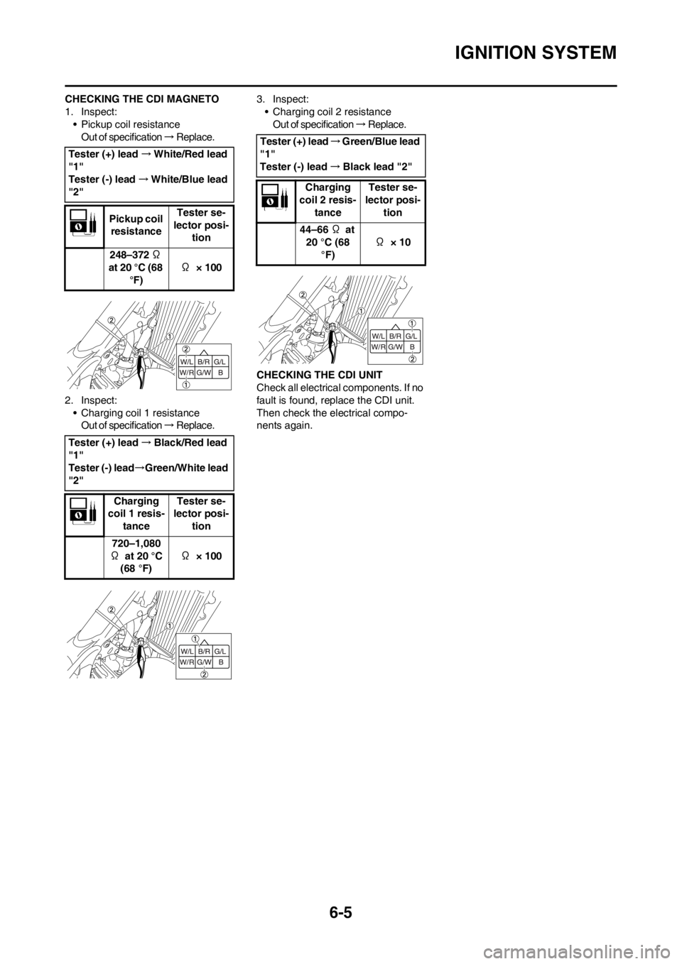
CHECKING THE CDI MAGNETO
1. Inspect:
• Pickup coil resistance
Out of specification → R e p l a c e .
2. Inspect:
• Charging coil 1 resistance
Out of specification → R e p l a c e . 3. Inspect:
• Charging coil 2 resistance
Out of specification → R e p l a c e .
CHECKING THE CDI UNIT
Check all electrical components. If no
fault is found, replace the CDI unit.
Then check the electrical compo-
nents again. Tester (+) lead→White/Red lead
"1"
Tester (-) lead→White/Blue lead
"2"
Pickup coil
resistanceTester se-
lector posi-
tion
248–372 Ω
at 20 °C (68
°F)Ω × 100
Tester (+) lead→Black/Red lead
"1"
Tester (-) lead→Green/White lead
"2"
Charging
coil 1 resis-
tanceTester se-
lector posi-
tion
720–1,080
Ω at 20 °C
(68 °F)Ω × 100
Tester (+) lead→Green/Blue lead
"1"
Tester (-) lead→Black lead "2"
Charging
coil 2 resis-
tanceTester se-
lector posi-
tion
44–66 Ω at
20 °C (68
°F)Ω × 10
Page 156 of 168

7-1
ENGINE
TUNING
ENGINE
CARBURETOR SETTING
• The role of fuel is to cool the engine,
and in the case of a 2-stroke en-
gine, to lubricate the engine in addi-
tion to power generation.
Accordingly, if a mixture of air and
fuel is too lean, abnormal combus-
tion will occur, and engine seizure
may result. If the mixture is too rich,
spark plugs will get wet with oil, thus
making it impossible to bring the en-
gine into full play or if the worst
comes to the worst, the engine may
stall.
• The richness of the air-fuel mixture
required for the engine will vary with
atmospheric conditions of the day
and therefore, the settings of the
carburetor must be properly suited
to the atmospheric conditions (air
pressure, humidity and tempera-
ture).
• Finally, the rider himself must make
a test-run and check his machine
for conditions (pick-up of engine
speed, road surface conditions)
and for the discoloration of the
spark plug(s). After taking these
into consideration, he must select
the best possible carburetor set-
tings.
It is advisable to make a note of set-
tings, atmospheric conditions, road
surface condition, lap-time, etc. so
that the memorandum can be used
as a reference useful for future.
ATMOSPHERIC CONDITIONS AND
CARBURETOR SETTINGS
The reason for the above tendency is
that the richness or leanness of a fuel
mixture depends on the density of the
air (i.e. the concentration of oxygen in
it).
• Higher temperature expands the air
with its resultant reduced density.• Higher humidity reduces the
amount of oxygen in the air by so
much of the water vapor in the
same air.
• Lower atmospheric pressure (at a
high altitude) reduces the density of
the air.
TEST RUN
After warming up the engine
equipped with the standard type car-
buretor(s) and spark plug(s), run two
or three laps of the circuit and check
the smooth operation of the engine
and discoloration of spark plug(s).
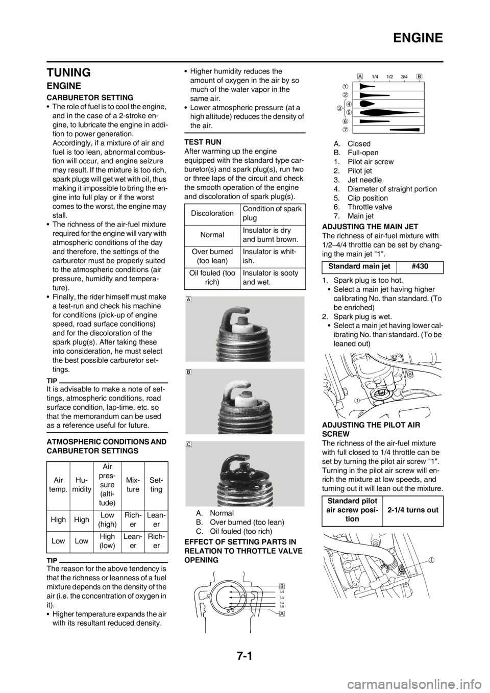
A. Normal
B. Over burned (too lean)
C. Oil fouled (too rich)
EFFECT OF SETTING PARTS IN
RELATION TO THROTTLE VALVE
OPENINGA. Closed
B. Full-open
1. Pilot air screw
2. Pilot jet
3. Jet needle
4. Diameter of straight portion
5. Clip position
6. Throttle valve
7. Main jet
ADJUSTING THE MAIN JET
The richness of air-fuel mixture with
1/2–4/4 throttle can be set by chang-
ing the main jet "1".
1. Spark plug is too hot.
• Select a main jet having higher
calibrating No. than standard. (To
be enriched)
2. Spark plug is wet.
• Select a main jet having lower cal-
ibrating No. than standard. (To be
leaned out)
ADJUSTING THE PILOT AIR
SCREW
The richness of the air-fuel mixture
with full closed to 1/4 throttle can be
set by turning the pilot air screw "1".
Turning in the pilot air screw will en-
rich the mixture at low speeds, and
turning out it will lean out the mixture. Air
temp.Hu-
midityAir
pres-
sure
(alti-
tude)Mix-
tureSet-
ting
High HighLow
(high)Rich-
erLean-
er
Low LowHigh
(low)Lean-
erRich-
er
DiscolorationCondition of spark
plug
NormalInsulator is dry
and burnt brown.
Over burned
(too lean)Insulator is whit-
ish.
Oil fouled (too
rich)Insulator is sooty
and wet.
Standard main jet #430
Standard pilot
air screw posi-
tion2-1/4 turns out
Page 161 of 168

7-6
CHASSIS
CHANGE OF THE HEAT RANGE
OF SPARK PLUGS
Judging from the discoloration of
spark plugs, if they are found improp-
er, it can be corrected by the following
two methods; changing carburetor
settings and changing the heat range
of spark plug.
• In principle, it is advisable to first
use spark plugs of standard heat
range, and judging from the discol-
oration of spark plugs, adjust carbu-
retor settings.
• If the calibration No. of the main jet
must be changed by ±30, it is advis-
able to change the heat range of
spark plugs and newly select the
proper main jet.
• When checking the discoloration of
spark plugs, be sure to stop the en-
gine immediately after a run and
check.
• Avoid racing.
• When changing the heat range of
spark plugs, never attempt to
change it more than ±1 rank.
• When using a spark plug other than
standard, check its heat range
against the standard and check that
it is a resistance type.
• Note that even if the discoloration
seems proper, it may slightly vary
with the spark plug maker and oil in
use.
CHASSIS
SELECTION OF THE SECONDARY
REDUCTION RATIO (SPROCKET)
• It is generally said that the second-
ary gear ratio should be reduced for
a longer straight portion of a speed
course and should be increased for
a course with many corners. Actual-
ly, however, as the speed depends
on the ground condition of the day
of the race, be sure to run through
the circuit to set the machine suit-
able for the entire course.
• In actuality, it is very difficult to
achieve settings suitable for the en-
tire course and some settings may
be sacrificed. Thus, the settings
should be matched to the portion of
the course that has the greatest ef-
fect on the race result. In such a
case, run through the entire course
while making notes of lap times to
find the best balance; then, deter-
mine the secondary reduction ratio.
• If a course has a long straight por-
tion where a machine can run at
maximum speed, the machine is
generally set such that it can devel-
op its maximum revolutions toward
the end of the straight line, with care
taken to avoid the engine over-rev-
ving.
Riding technique varies from rider to
rider and the performance of a ma-
chine also vary from machine to ma-
chine. Therefore, do not imitate other
rider's settings from the beginning but
choose your own setting according to
the level of your riding technique.
DRIVE AND REAR WHEEL
SPROCKETS SETTING PARTSTIRE PRESSURE
Tire pressure should be adjust to suit
the road surface condition of the cir-
cuit.
• Under a rainy, muddy, sandy, or
slippery condition, the tire pressure
should be lower for a larger area of
contact with the road surface.
• Under a stony or hard road condi-
tion, the tire pressure should be
higher to prevent a flat tire.
FRONT FORK SETTING
The front fork setting should be made
depending on the rider's feeling of an
actual run and the circuit conditions.
The front fork setting includes the fol-
lowing three factors:
1. Setting of air spring characteris-
tics
• Change the fork oil amount.
2. Setting of spring preload
• Change the spring.
3. Setting of damping force
• Change the compression damp-
ing.
• Change the rebound damping.
The spring acts on the load and
the damping force acts on the
cushion travel speed.
CHANGE IN AMOUNT AND
CHARACTERISTICS OF FORK OIL
Damping characteristic near the final
stroke can be changed by changing
the fork oil amount. Standard spark
plugBR9EVX/NGK
(resistance
type)
Secondary reduction ratio =
Number of rear wheel sprocket
teeth/Number of drive sprocket
teeth
Standard second-
ary reduction ratio3.692 (48/13)
Part name Size Part number
Drive
sprocket
"1"
(STD) 13T 9383B-13218
Rear wheel
sprocket
"2"
47T 1C3-25447-00
(STD) 48T 1C3-25448-00
49T 1C3-25449-00
50T 1C3-25450-00
51T 1C3-25451-00
52T 1C3-25452-00
Standard tire pressure:
100 kPa (1.0 kgf/cm2,
15 psi)
Extent of adjustment:
60–80 kPa (0.6–0.8
kgf/cm
2, 9.0–12 psi)
Extent of adjustment:
100–120 kPa (1.0–1.2
kgf/cm
2, 15–18 psi)
Page 162 of 168

7-7
CHASSIS
Adjust the oil amount in 5 cm 3 (0.2
Imp oz, 0.2 US oz) increments or
decrements. Too small oil amount
causes the front fork to produce a
noise at full rebound or the rider to
feel some pressure on his hands
or body. Alternatively, too large oil
amount will cause the air spring
characteristics to have a tendency
to be stiffer with the consequent
deteriorated performance and
characteristics. Therefore, adjust
the front fork within the specified
range.
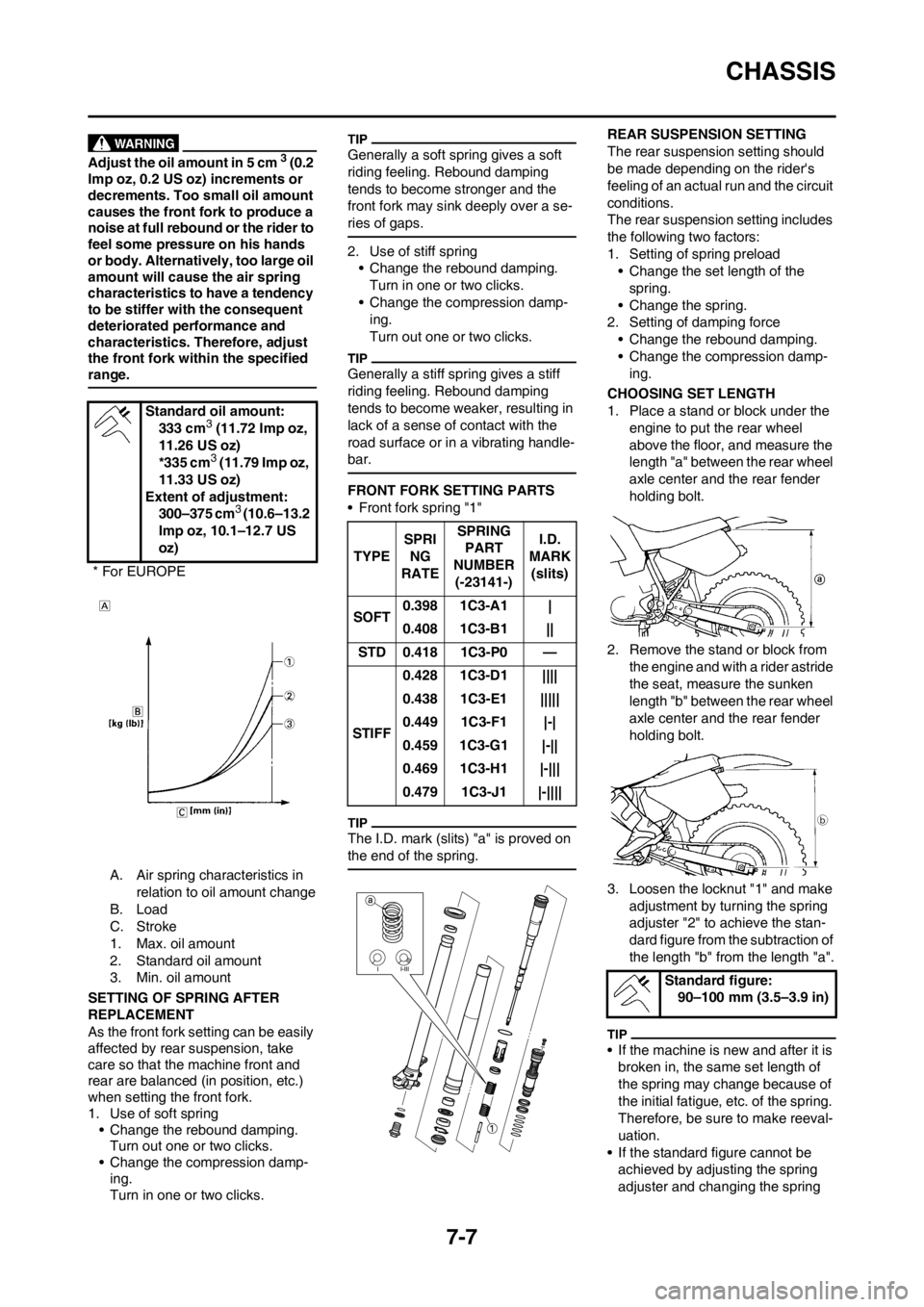
A. Air spring characteristics in
relation to oil amount change
B. Load
C. Stroke
1. Max. oil amount
2. Standard oil amount
3. Min. oil amount
SETTING OF SPRING AFTER
REPLACEMENT
As the front fork setting can be easily
affected by rear suspension, take
care so that the machine front and
rear are balanced (in position, etc.)
when setting the front fork.
1. Use of soft spring
• Change the rebound damping.
Turn out one or two clicks.
• Change the compression damp-
ing.
Turn in one or two clicks.
Generally a soft spring gives a soft
riding feeling. Rebound damping
tends to become stronger and the
front fork may sink deeply over a se-
ries of gaps.
2. Use of stiff spring
• Change the rebound damping.
Turn in one or two clicks.
• Change the compression damp-
ing.
Turn out one or two clicks.
Generally a stiff spring gives a stiff
riding feeling. Rebound damping
tends to become weaker, resulting in
lack of a sense of contact with the
road surface or in a vibrating handle-
bar.
FRONT FORK SETTING PARTS
• Front fork spring "1"
The I.D. mark (slits) "a" is proved on
the end of the spring.
REAR SUSPENSION SETTING
The rear suspension setting should
be made depending on the rider's
feeling of an actual run and the circuit
conditions.
The rear suspension setting includes
the following two factors:
1. Setting of spring preload
• Change the set length of the
spring.
• Change the spring.
2. Setting of damping force
• Change the rebound damping.
• Change the compression damp-
ing.
CHOOSING SET LENGTH
1. Place a stand or block under the
engine to put the rear wheel
above the floor, and measure the
length "a" between the rear wheel
axle center and the rear fender
holding bolt.
2. Remove the stand or block from
the engine and with a rider astride
the seat, measure the sunken
length "b" between the rear wheel
axle center and the rear fender
holding bolt.
3. Loosen the locknut "1" and make
adjustment by turning the spring
adjuster "2" to achieve the stan-
dard figure from the subtraction of
the length "b" from the length "a".
• If the machine is new and after it is
broken in, the same set length of
the spring may change because of
the initial fatigue, etc. of the spring.
Therefore, be sure to make reeval-
uation.
• If the standard figure cannot be
achieved by adjusting the spring
adjuster and changing the spring Standard oil amount:
333 cm
3 (11.72 Imp oz,
11.26 US oz)
*335 cm
3 (11.79 Imp oz,
11.33 US oz)
Extent of adjustment:
300–375 cm
3 (10.6–13.2
Imp oz, 10.1–12.7 US
oz)
* For EUROPE
TYPESPRI
NG
RATESPRING
PART
NUMBER
(-23141-)I.D.
MARK
(slits)
SOFT0.398 1C3-A1 |
0.408 1C3-B1 ||
STD 0.418 1C3-P0 —
STIFF0.428 1C3-D1 ||||
0.438 1C3-E1 |||||
0.449 1C3-F1 |-|
0.459 1C3-G1 |-||
0.469 1C3-H1 |-|||
0.479 1C3-J1 |-||||
Standard figure:
90–100 mm (3.5–3.9 in)
Page 165 of 168

7-10
CHASSIS
SUSPENSION SETTING (FRONT FORK)
• If any of the following symptoms is experienced with the standard position as the base, make resetting by reference to
the adjustment procedure given in the same chart.
• Before any change, set the rear shock absorber sunken length to the standard figure 90–100 mm (3.5–3.9 in).
SymptomSection
Check Adjust
JumpLarge
gapMedi-
um
gapSmall
gap
Stiff over entire
range○○○Compression damping Turn adjuster counterclockwise (about 2 clicks) to
decrease damping.
Oil amount Decrease oil amount by about 5–10 cm
3
(0.2–0.4 Imp oz, 0.2–0.3 US oz).
Spring Replace with soft spring.
Unsmooth move-
ment over entire
range○○○○Outer tube Check for any bends, dents, and other noticeable
scars, etc. If any, replace affected parts.
Inner tube
Slide metal Replace with a new one for extended use.
Piston metal Replace with a new one for extended use.
Under bracket tighten-
ing torqueRetighten to specified torque.
Poor initial move-
ment○Rebound damping Turn adjuster counterclockwise (about 2 clicks) to
decrease damping.
Oil seal Apply grease in oil seal wall.
Soft over entire
range, bottoming
out○○Compression damping Turn adjuster clockwise (about 2 clicks) to in-
crease damping.
Oil amount Increase oil amount by about 5–10 cm
3
(0.2–0.4 Imp oz, 0.2–0.3 US oz).
Spring Replace with stiff spring.
Stiff toward stroke
end○Oil amountDecrease oil amount by about 5 cm
3
(0.2 Imp oz,0.2 US oz).
Soft toward stroke
end, bottoming out○Oil amountIncrease oil amount by about 5 cm
3
(0.2 Imp oz,0.2 US oz).
Stiff initial move-
ment○○○○Compression dampingTurn adjuster counterclockwise (about 2 clicks) to
decrease damping.
Low front, tending to
lower front posture○○Compression damping Turn adjuster clockwise (about 2 clicks) to in-
crease damping.
Rebound damping Turn adjuster counterclockwise (about 2 clicks) to
decrease damping.
Balance with rear end Set sunken length for 95–100 mm (3.7–3.9 in)
when one passenger is astride seat
(lower rear posture).
Oil amount Increase oil amount by about 5 cm
3
(0.2 Imp oz, 0.2 US oz).
"Obtrusive" front,
tending to upper
front posture○○Compression damping Turn adjuster counterclockwise (about 2 clicks) to
decrease damping.
Balance with rear end Set sunken length for 90–95 mm (3.5–3.7 in)
when one passenger is astride seat
(upper rear posture).
Spring Replace with soft spring.
Oil amount Decrease oil amount by about 5–10 cm
3
(0.2–0.4 Imp oz, 0.2–0.3 US oz).