2013 YAMAHA YZ125LC oil
[x] Cancel search: oilPage 56 of 168
3-13
CHASSIS
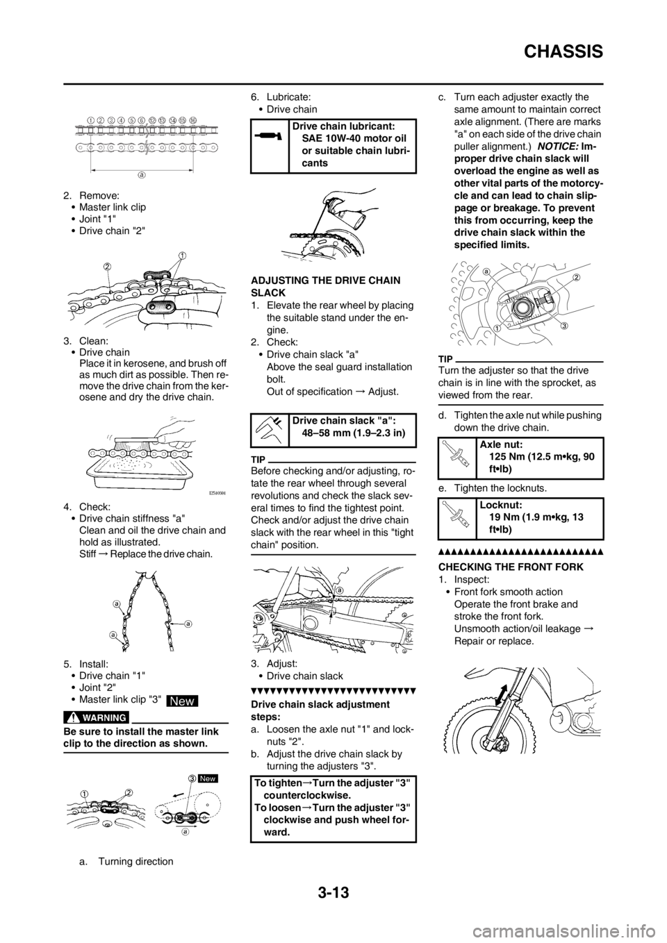
2. Remove:
• Master link clip
•Joint "1"
• Drive chain "2"
3. Clean:
• Drive chain
Place it in kerosene, and brush off
as much dirt as possible. Then re-
move the drive chain from the ker-
osene and dry the drive chain.
4. Check:
• Drive chain stiffness "a"
Clean and oil the drive chain and
hold as illustrated.
Stiff → Replace the drive chain.
5. Install:
• Drive chain "1"
•Joint "2"
• Master link clip "3"
Be sure to install the master link
clip to the direction as shown.
a. Turning direction6. Lubricate:
• Drive chain
ADJUSTING THE DRIVE CHAIN
SLACK
1. Elevate the rear wheel by placing
the suitable stand under the en-
gine.
2. Check:
• Drive chain slack "a"
Above the seal guard installation
bolt.
Out of specification → Adjust.
Before checking and/or adjusting, ro-
tate the rear wheel through several
revolutions and check the slack sev-
eral times to find the tightest point.
Check and/or adjust the drive chain
slack with the rear wheel in this "tight
chain" position.
3. Adjust:
• Drive chain slack
Drive chain slack adjustment
steps:
a. Loosen the axle nut "1" and lock-
nuts "2".
b. Adjust the drive chain slack by
turning the adjusters "3".c. Turn each adjuster exactly the
same amount to maintain correct
axle alignment. (There are marks
"a" on each side of the drive chain
puller alignment.) NOTICE: Im-
proper drive chain slack will
overload the engine as well as
other vital parts of the motorcy-
cle and can lead to chain slip-
page or breakage. To prevent
this from occurring, keep the
drive chain slack within the
specified limits.
Turn the adjuster so that the drive
chain is in line with the sprocket, as
viewed from the rear.
d. Tighten the axle nut while pushing
down the drive chain.
e. Tighten the locknuts.
CHECKING THE FRONT FORK
1. Inspect:
• Front fork smooth action
Operate the front brake and
stroke the front fork.
Unsmooth action/oil leakage →
Repair or replace.
Drive chain lubricant:
SAE 10W-40 motor oil
or suitable chain lubri-
cants
Drive chain slack "a":
48–58 mm (1.9–2.3 in)
To tighten→Turn the adjuster "3"
counterclockwise.
To loosen→Turn the adjuster "3"
clockwise and push wheel for-
ward.
Axle nut:
125 Nm (12.5 m•kg, 90
ft•lb)
Locknut:
19 Nm (1.9 m•kg, 13
ft•lb)
Page 57 of 168
3-14
CHASSIS
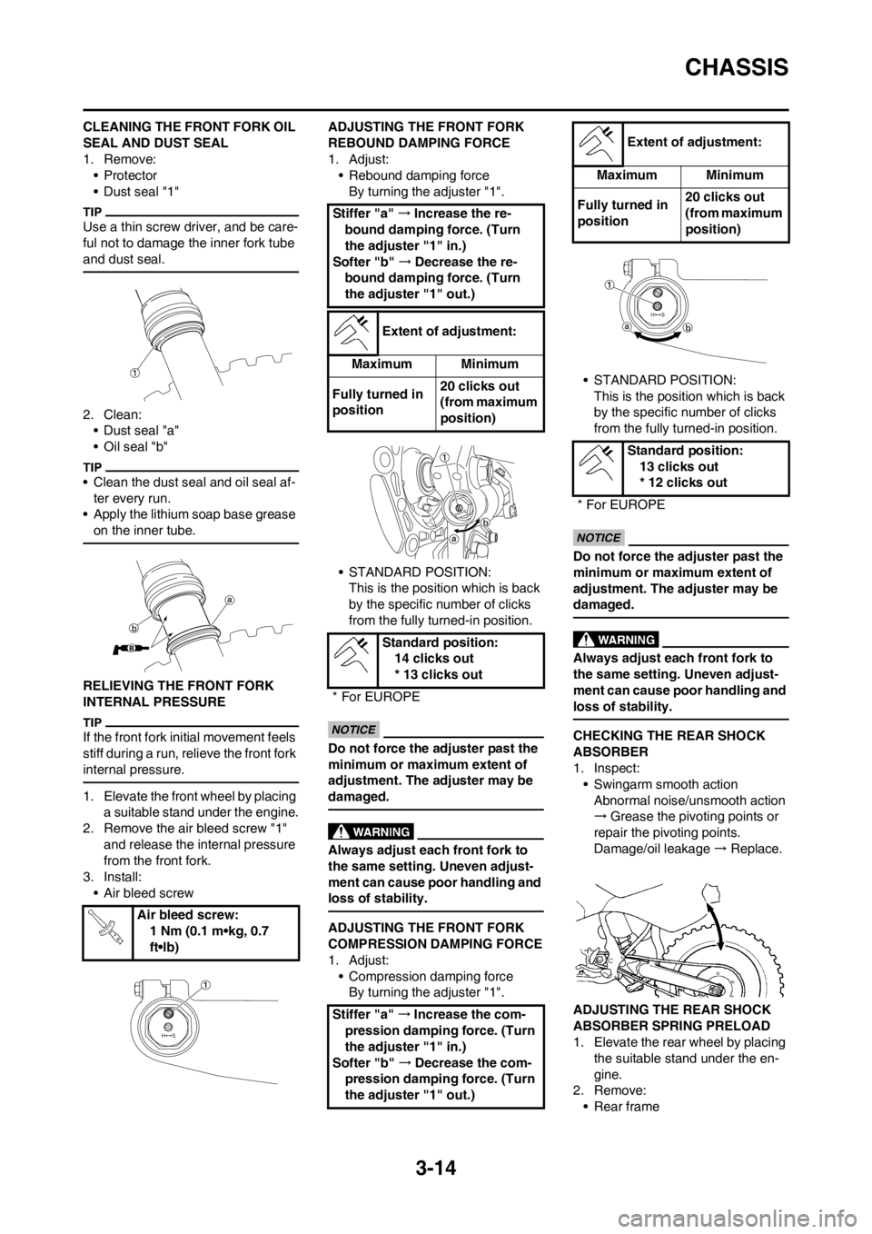
CLEANING THE FRONT FORK OIL
SEAL AND DUST SEAL
1. Remove:
•Protector
• Dust seal "1"
Use a thin screw driver, and be care-
ful not to damage the inner fork tube
and dust seal.
2. Clean:
• Dust seal "a"
• Oil seal "b"
• Clean the dust seal and oil seal af-
ter every run.
• Apply the lithium soap base grease
on the inner tube.
RELIEVING THE FRONT FORK
INTERNAL PRESSURE
If the front fork initial movement feels
stiff during a run, relieve the front fork
internal pressure.
1. Elevate the front wheel by placing
a suitable stand under the engine.
2. Remove the air bleed screw "1"
and release the internal pressure
from the front fork.
3. Install:
• Air bleed screwADJUSTING THE FRONT FORK
REBOUND DAMPING FORCE
1. Adjust:
• Rebound damping force
By turning the adjuster "1".
• STANDARD POSITION:
This is the position which is back
by the specific number of clicks
from the fully turned-in position.
Do not force the adjuster past the
minimum or maximum extent of
adjustment. The adjuster may be
damaged.
Always adjust each front fork to
the same setting. Uneven adjust-
ment can cause poor handling and
loss of stability.
ADJUSTING THE FRONT FORK
COMPRESSION DAMPING FORCE
1. Adjust:
• Compression damping force
By turning the adjuster "1".• STANDARD POSITION:
This is the position which is back
by the specific number of clicks
from the fully turned-in position.
Do not force the adjuster past the
minimum or maximum extent of
adjustment. The adjuster may be
damaged.
Always adjust each front fork to
the same setting. Uneven adjust-
ment can cause poor handling and
loss of stability.
CHECKING THE REAR SHOCK
ABSORBER
1. Inspect:
• Swingarm smooth action
Abnormal noise/unsmooth action
→Grease the pivoting points or
repair the pivoting points.
Damage/oil leakage → Replace.
ADJUSTING THE REAR SHOCK
ABSORBER SPRING PRELOAD
1. Elevate the rear wheel by placing
the suitable stand under the en-
gine.
2. Remove:
• Rear frame Air bleed screw:
1 Nm (0.1 m•kg, 0.7
ft•lb)
Stiffer "a" →Increase the re-
bound damping force. (Turn
the adjuster "1" in.)
Softer "b" →Decrease the re-
bound damping force. (Turn
the adjuster "1" out.)
Extent of adjustment:
Maximum Minimum
Fully turned in
position20 clicks out
(from maximum
position)
Standard position:
14 clicks out
* 13 clicks out
* For EUROPE
Stiffer "a" →Increase the com-
pression damping force. (Turn
the adjuster "1" in.)
Softer "b" →Decrease the com-
pression damping force. (Turn
the adjuster "1" out.)
Extent of adjustment:
Maximum Minimum
Fully turned in
position20 clicks out
(from maximum
position)
Standard position:
13 clicks out
* 12 clicks out
* For EUROPE
Page 61 of 168
3-18
CHASSIS
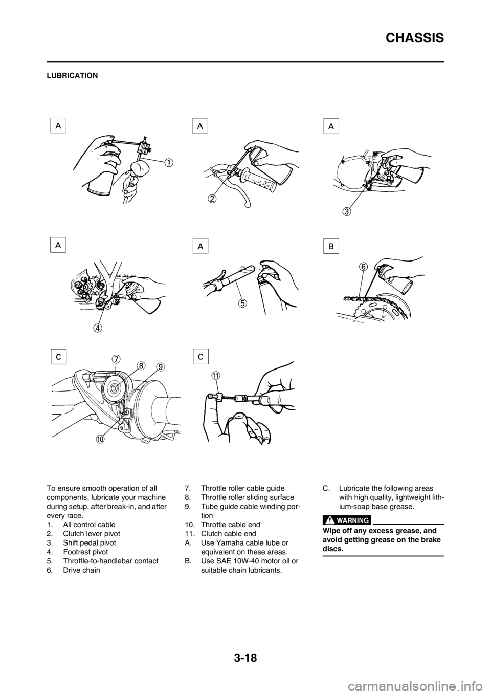
LUBRICATION
To ensure smooth operation of all
components, lubricate your machine
during setup, after break-in, and after
every race.
1. All control cable
2. Clutch lever pivot
3. Shift pedal pivot
4. Footrest pivot
5. Throttle-to-handlebar contact
6. Drive chain7. Throttle roller cable guide
8. Throttle roller sliding surface
9. Tube guide cable winding por-
tion
10. Throttle cable end
11. Clutch cable end
A. Use Yamaha cable lube or
equivalent on these areas.
B. Use SAE 10W-40 motor oil or
suitable chain lubricants.C. Lubricate the following areas
with high quality, lightweight lith-
ium-soap base grease.
Wipe off any excess grease, and
avoid getting grease on the brake
discs.
Page 79 of 168
4-17
CYLINDER HEAD, CYLINDER AND PISTON
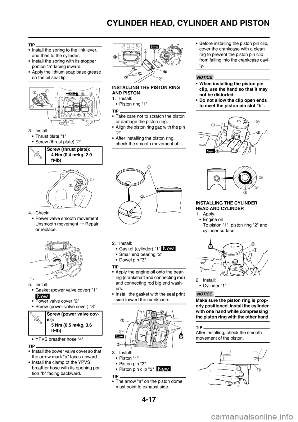
• Install the spring to the link lever,
and then to the cylinder.
• Install the spring with its stopper
portion "a" facing inward.
• Apply the lithium soap base grease
on the oil seal lip.
3. Install:
• Thrust plate "1"
• Screw (thrust plate) "2"
4. Check:
• Power valve smooth movement
Unsmooth movement → Repair
or replace.
5. Install:
• Gasket (power valve cover) "1"
• Power valve cover "2"
• Screw (power valve cover) "3"
• YPVS breather hose "4"
• Install the power valve cover so that
the arrow mark "a" faces upward.
• Install the clamp of the YPVS
breather hose with its opening por-
tion "b" facing backward.
INSTALLING THE PISTON RING
AND PISTON
1. Install:
• Piston ring "1"
• Take care not to scratch the piston
or damage the piston ring.
• Align the piston ring gap with the pin
"2".
• After installing the piston ring,
check the smooth movement of it.
2. Install:
• Gasket (cylinder) "1"
• Small end bearing "2"
• Dowel pin "3"
• Apply the engine oil onto the bear-
ing (crankshaft and connecting rod)
and connecting rod big end wash-
ers.
• Install the gasket with the seal print
side toward the crankcase.
3. Install:
•Piston "1"
• Piston pin "2"
• Piston pin clip "3"
• The arrow "a" on the piston dome
must point to exhaust side.• Before installing the piston pin clip,
cover the crankcase with a clean
rag to prevent the piston pin clip
from falling into the crankcase cavi-
ty.
• When installing the piston pin
clip, use the hand so that it may
not be distorted.
• Do not allow the clip open ends
to meet the piston pin slot "b".
INSTALLING THE CYLINDER
HEAD AND CYLINDER
1. Apply:
• Engine oil
To piston "1", piston ring "2" and
cylinder surface.
2. Install:
• Cylinder "1"
Make sure the piston ring is prop-
erly positioned. Install the cylinder
with one hand while compressing
the piston ring with the other hand.
After installing, check the smooth
movement of the piston.
Screw (thrust plate):
4 Nm (0.4 m•kg, 2.9
ft•lb)
Screw (power valve cov-
er):
5 Nm (0.5 m•kg, 3.6
ft•lb)
Page 81 of 168
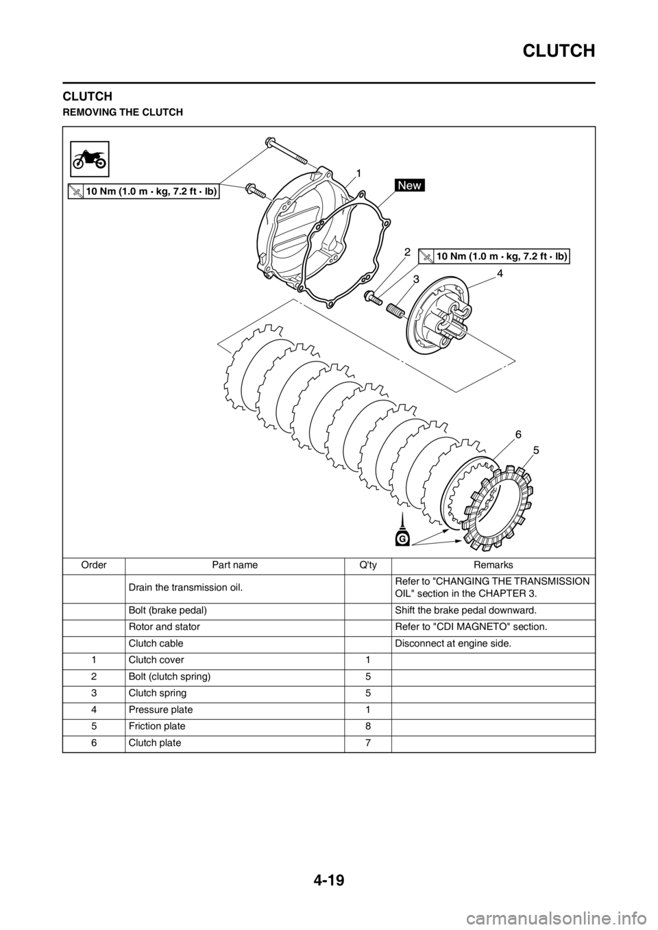
4-19
CLUTCH
CLUTCH
REMOVING THE CLUTCH
Order Part name Q'ty Remarks
Drain the transmission oil.Refer to "CHANGING THE TRANSMISSION
OIL" section in the CHAPTER 3.
Bolt (brake pedal) Shift the brake pedal downward.
Rotor and stator Refer to "CDI MAGNETO" section.
Clutch cable Disconnect at engine side.
1 Clutch cover 1
2 Bolt (clutch spring) 5
3 Clutch spring 5
4 Pressure plate 1
5 Friction plate 8
6 Clutch plate 7
10 Nm (1.0 m kg, 7.2 ft lb)
10 Nm (1.0 m kg, 7.2 ft lb)
Page 83 of 168
4-21
CLUTCH
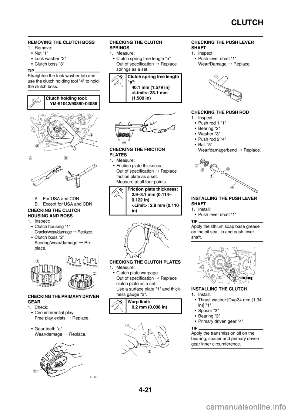
REMOVING THE CLUTCH BOSS
1. Remove:
•Nut "1"
• Lock washer "2"
• Clutch boss "3"
Straighten the lock washer tab and
use the clutch holding tool "4" to hold
the clutch boss.
A. For USA and CDN
B. Except for USA and CDN
CHECKING THE CLUTCH
HOUSING AND BOSS
1. Inspect:
• Clutch housing "1"
Cracks/wear/damage → R e p l a c e .
• Clutch boss "2"
Scoring/wear/damage → Re-
place.
CHECKING THE PRIMARY DRIVEN
GEAR
1. Check:
• Circumferential play
Free play exists → Replace.
• Gear teeth "a"
Wear/damage → Replace. CHECKING THE CLUTCH
SPRINGS
1. Measure:
• Clutch spring free length "a"
Out of specification → Replace
springs as a set.
CHECKING THE FRICTION
PLATES
1. Measure:
• Friction plate thickness
Out of specification → Replace
friction plate as a set.
Measure at all four points.
CHECKING THE CLUTCH PLATES
1. Measure:
• Clutch plate warpage
Out of specification → Replace
clutch plate as a set.
Use a surface plate "1" and thick-
ness gauge "2".CHECKING THE PUSH LEVER
SHAFT
1. Inspect:
• Push lever shaft "1"
Wear/Damage → Replace.
CHECKING THE PUSH ROD
1. Inspect:
• Push rod 1 "1"
• Bearing "2"
• Washer "3"
• Push rod 2 "4"
•Ball "5"
Wear/damage/bend → Replace.
INSTALLING THE PUSH LEVER
SHAFT
1. Install:
• Push lever shaft "1"
Apply the lithium soap base grease
on the oil seal lip and push lever
shaft.
INSTALLING THE CLUTCH
1. Install:
• Thrust washer [D=ø34 mm (1.34
in)] "1"
• Spacer "2"
• Bearing "3"
• Primary driven gear "4"
Apply the transmission oil on the
bearing, spacer and primary driven
gear inner circumference.
Clutch holding tool:
YM-91042/90890-04086
Clutch spring free length
"a":
40.1 mm (1.579 in)
(1.500 in)
Friction plate thickness:
2.9–3.1 mm (0.114–
0.122 in)
in)
Warp limit:
0.2 mm (0.008 in)
Page 84 of 168
![YAMAHA YZ125LC 2013 Owners Manual 4-22
CLUTCH
2. Install:
• Thrust washer [D=ø34 mm (1.34
in)] "1"
• Clutch boss "2"
3. Install:
• Lock washer "1"
• Nut (clutch boss) "2"
Use the clutch holding tool "3" to hold
the clutc YAMAHA YZ125LC 2013 Owners Manual 4-22
CLUTCH
2. Install:
• Thrust washer [D=ø34 mm (1.34
in)] "1"
• Clutch boss "2"
3. Install:
• Lock washer "1"
• Nut (clutch boss) "2"
Use the clutch holding tool "3" to hold
the clutc](/manual-img/51/53901/w960_53901-83.png)
4-22
CLUTCH
2. Install:
• Thrust washer [D=ø34 mm (1.34
in)] "1"
• Clutch boss "2"
3. Install:
• Lock washer "1"
• Nut (clutch boss) "2"
Use the clutch holding tool "3" to hold
the clutch boss.
A. For USA and CDN
B. Except for USA and CDN
4. Bend the lock washer "1" tab.5. Install:
• Friction plate "1"
• Clutch plate "2"
• Install the clutch plates and friction
plates alternately on the clutch
boss, starting with a friction plate
and ending with a friction plate.
• Apply the transmission oil on the
friction plates and clutch plates.
6. Install:
•Bearing "1"
• Washer "2"
• Circlip "3"
To push rod 1 "4".
Apply the lithium soap base grease
on the bearing and washer.
7. Install:
• Push rod 2 "1"
• Ball "2"
• Push rod 1 "3"
Apply the transmission oil on the
push rod 1, 2 and ball.
8. Install:
• Pressure plate "1"9. Install:
• Clutch spring "1"
• Bolt (clutch spring) "2"
Tighten the bolts in stage, using a
crisscross pattern.
10. Install:
• Dowel pin "1"
• Gasket (clutch cover) "2"
11. Install:
• Clutch cover "1"
• Bolt (clutch cover) "2"
Tighten the bolts in stage, using a
crisscross pattern.
12. Install:
• O-ring "1"
• Clutch cable "2"
Apply the lithium soap base grease
on the O-ring.
Nut (clutch boss):
80 Nm (8.0 m•kg, 58
ft•lb)
Clutch holding tool:
YM-91042/90890-04086
Bolt (clutch spring):
10 Nm (1.0 m•kg, 7.2
ft•lb)
Bolt (clutch cover):
10 Nm (1.0 m•kg, 7.2
ft•lb)
Page 85 of 168
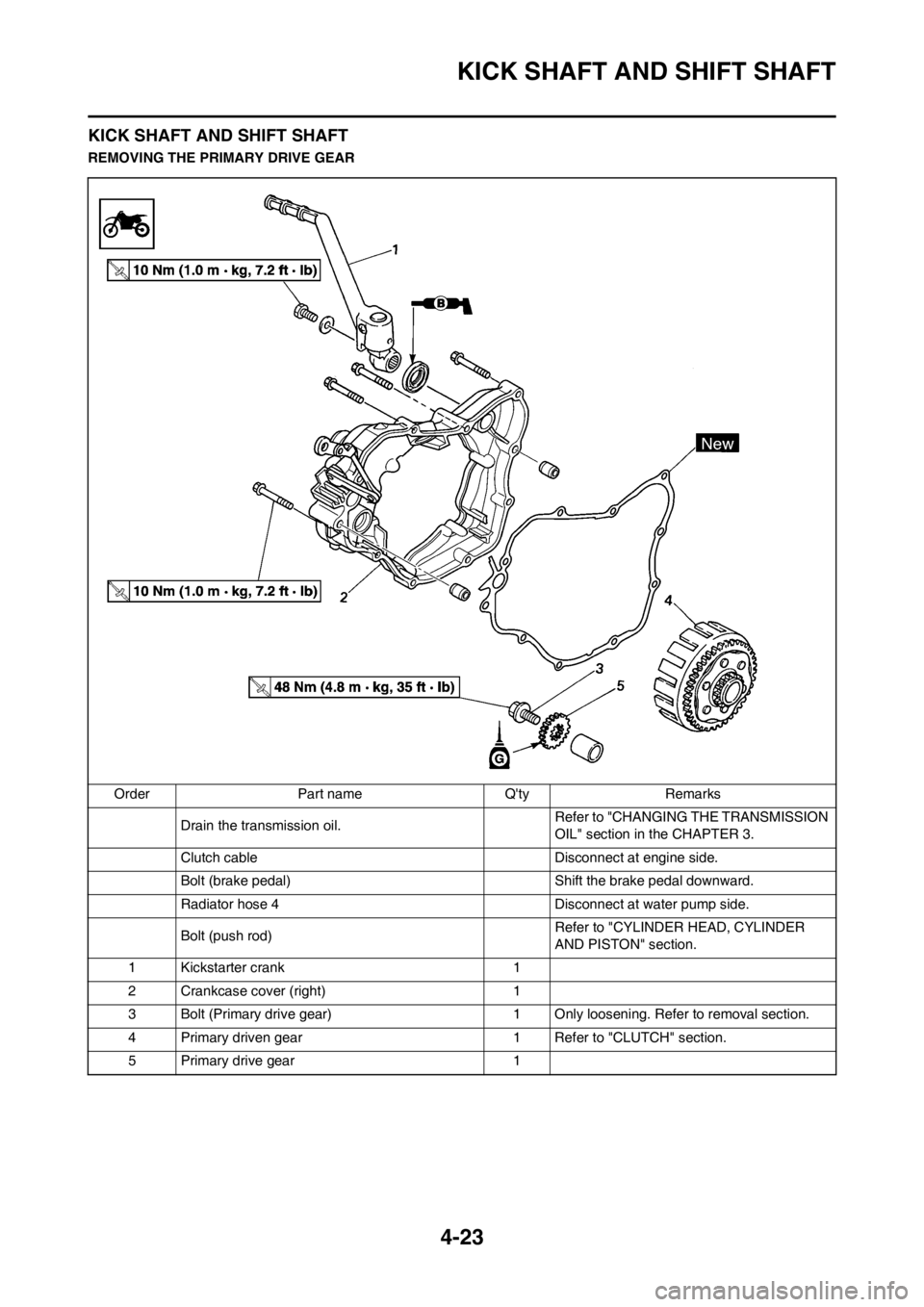
4-23
KICK SHAFT AND SHIFT SHAFT
KICK SHAFT AND SHIFT SHAFT
REMOVING THE PRIMARY DRIVE GEAR
Order Part name Q'ty Remarks
Drain the transmission oil. Refer to "CHANGING THE TRANSMISSION
OIL" section in the CHAPTER 3.
Clutch cable Disconnect at engine side.
Bolt (brake pedal) Shift the brake pedal downward.
Radiator hose 4 Disconnect at water pump side.
Bolt (push rod)Refer to "CYLINDER HEAD, CYLINDER
AND PISTON" section.
1 Kickstarter crank 1
2 Crankcase cover (right) 1
3 Bolt (Primary drive gear) 1 Only loosening. Refer to removal section.
4 Primary driven gear 1 Refer to "CLUTCH" section.
5 Primary drive gear 1