Page 68 of 168

4-6
RADIATOR
HANDLING NOTE
Do not remove the radiator cap
when the engine and radiator are
hot. Scalding hot fluid and steam
may be blown out under pressure,
which could cause serious injury.
When the engine has cooled, open
the radiator cap by the following
procedure:
Place a thick rag, like a towel, over
the radiator cap, slowly rotate the
cap counterclockwise to the de-
tent. This procedure allows any re-
sidual pressure to escape. When
the hissing sound has stopped,
press down on the cap while turn-
ing counterclockwise and remove
it.
CHECKING THE RADIATOR
1. Inspect:
• Radiator core "1"
Obstruction → Blow out with com-
pressed air through rear of the ra-
diator.
Bent fin → Repair/replace.
INSTALLING THE RADIATOR
1. Install:
• Radiator breather hose "1"
• Radiator hose 3 "2"
• Radiator hose 1 "3"
To right radiator "4".
Clamp the radiator hose in the direc-
tion as shown.
2. Install:
• Right radiator "1"
• Washer "2"
• Bolt (right radiator) "3"
• Radiator hose 4 "4"
Refer to "CABLE ROUTING DIA-
GRAM" section in the CHAPTER
2.
3. Install:
• Left radiator "1"
• Washer "2"
• Bolt (left radiator) "3"
• Radiator hose 2 "4"
Refer to "CABLE ROUTING DIA-
GRAM" section in the CHAPTER
2.
4. Tighten:
• Radiator hose clamp 1, 3 "5"
5. Install:
• Radiator guard "1"
• Bolt (radiator guard) "2"
Fit the hook "a" on the inner side first
into the radiator.
Radiator hose 3:
2 Nm (0.2 m•kg, 1.4
ft•lb)
Radiator hose 1:
2 Nm (0.2 m•kg, 1.4
ft•lb)
Bolt (right radiator):
10 Nm (1.0 m•kg, 7.2
ft•lb)
Radiator hose 4:
2 Nm (0.2 m•kg, 1.4
ft•lb)
Bolt (left radiator):
10 Nm (1.0 m•kg, 7.2
ft•lb)
Radiator hose 2:
2 Nm (0.2 m•kg, 1.4
ft•lb)
Radiator hose clamp 1, 3:
2 Nm (0.2 m•kg, 1.4
ft•lb)
Bolt (radiator guard):
10 Nm (1.0 m•kg, 7.2
ft•lb)
Page 74 of 168
4-12
CYLINDER HEAD, CYLINDER AND PISTON
CYLINDER HEAD, CYLINDER AND PISTON
REMOVING THE CYLINDER HEAD AND CYLINDER
Order Part name Q'ty Remarks
Seat and fuel tank Refer to "SEAT, FUEL TANK AND SIDE
COVERS" section.
Exhaust pipe and silencerRefer to "EXHAUST PIPE AND SILENCER"
section.
Radiator Refer to "RADIATOR" section.
1 Spark plug 1
2 Engine bracket 2
3 Nut (cylinder head) 5Loosen each nut 1/4 turn, and remove them
after all nuts are loosened.
4 Cylinder head 1
5 Power valve housing 1
6 Push rod 1 Refer to removal section.
7 Nut (cylinder) 4
8 Cylinder 1
5 Nm (0.5 m kg, 3.6 ft lb)
4 Nm (0.4 m kg, 2.9 ft lb)
13 Nm (1.3 m kg, 9.4 ft lb)
28 Nm (2.8 m kg, 20 ft lb)
20 Nm (2.0 m kg, 14 ft lb)
30 Nm (3.0 m kg, 22 ft lb)
34 Nm (3.4 m kg, 24 ft lb)
Page 85 of 168
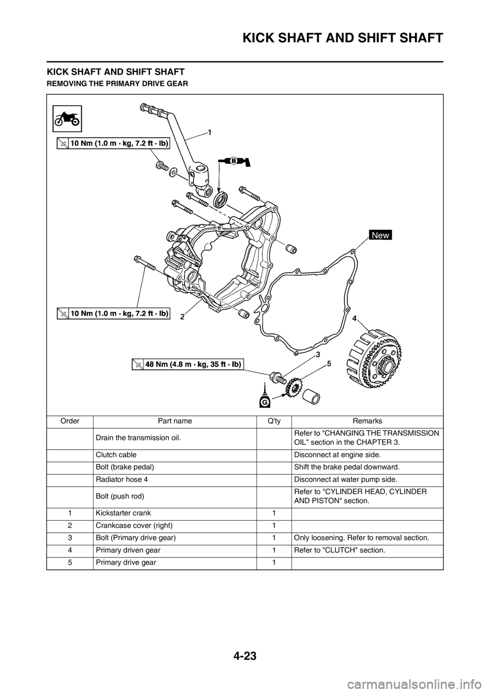
4-23
KICK SHAFT AND SHIFT SHAFT
KICK SHAFT AND SHIFT SHAFT
REMOVING THE PRIMARY DRIVE GEAR
Order Part name Q'ty Remarks
Drain the transmission oil. Refer to "CHANGING THE TRANSMISSION
OIL" section in the CHAPTER 3.
Clutch cable Disconnect at engine side.
Bolt (brake pedal) Shift the brake pedal downward.
Radiator hose 4 Disconnect at water pump side.
Bolt (push rod)Refer to "CYLINDER HEAD, CYLINDER
AND PISTON" section.
1 Kickstarter crank 1
2 Crankcase cover (right) 1
3 Bolt (Primary drive gear) 1 Only loosening. Refer to removal section.
4 Primary driven gear 1 Refer to "CLUTCH" section.
5 Primary drive gear 1
Page 95 of 168
4-33
CDI MAGNETO
CDI MAGNETO
REMOVING THE CDI MAGNETO
Order Part name Q'ty Remarks
Seat and fuel tankRefer to "SEAT, FUEL TANK AND SIDE
COVERS" section.
Bolt (Radiator) Refer to "RADIATOR" section.
Disconnect the CDI magneto lead.
1 Left crankcase cover 1
2 Nut (rotor) 1 Refer to removal section.
3 Rotor 1 Refer to removal section.
4 Stator 1
5 Woodruff key 1
Page 97 of 168
4-35
ENGINE REMOVAL
ENGINE REMOVAL
REMOVING THE ENGINE
Order Part name Q'ty Remarks
Hold the machine by placing the suitable stand
under the engine.Refer to "HANDLING NOTE".
Seat and fuel tank Refer to "SEAT, FUEL TANK AND SIDE
COVERS" section.
Carburetor Refer to "CARBURETOR AND REED
VALVE" section.
Exhaust pipe and silencer Refer to "EXHAUST PIPE AND SILENCER"
section.
Clutch cable Disconnect at the engine side.
Radiator Refer to "RADIATOR" section.
Spark plug cap
Disconnect the CDI magneto lead.
1 Drive chain sprocket cover 1
2 Nut (drive sprocket) 1 Refer to removal section.
3 Lock washer 1 Refer to removal section.
4 Drive sprocket 1 Refer to removal section.
5Clip 1
6 Bolt (brake pedal) 1
26 Nm (2.6 m kg, 19 ft lb)
64 Nm (6.4 m kg, 46 ft lb)
64 Nm (6.4 m kg, 46 ft lb)
85 Nm (8.5 m kg, 61 ft lb)
75 Nm (7.5 m kg, 54 ft lb)
5 Nm (0.5 m kg, 3.6 ft lb)
34 Nm (3.4 m kg, 24 ft lb)
Page:
< prev 1-8 9-16 17-24