Page 121 of 156

8-33
8
●Insufficient brake fluid may allow air to enter
the brake system, reducing braking perfor-
mance.●Clean the filler cap before removing. Use
only DOT 4 brake fluid from a sealed contain-
er.●Use only the specified brake fluid; otherwise,
the rubber seals may deteriorate, causing
leakage.●Refill with the same type of brake fluid. Add-
ing a brake fluid other than DOT 4 may result
in a harmful chemical reaction.●Be careful that water does not enter the
brake fluid reservoir when refilling. Water
will significantly lower the boiling point of
the fluid and may result in vapor lock.NOTICEECB01160Brake fluid may damage painted surfaces or
plastic parts. Always clean up spilled fluid im-
mediately.As the brake pads wear, it is normal for the brake
fluid level to gradually go down. A low brake fluid
level may indicate worn brake pads and/or brake
system leakage; therefore, be sure to check thebrake pads for wear and the brake system for leak-
age. If the brake fluid level goes down suddenly,
have a Yamaha dealer check the cause before fur-
ther riding.
EBU24291Changing the brake fluid Have a Yamaha dealer change the brake fluid at
the intervals specified in the TIP after the periodic
maintenance and lubrication chart. In addition,
have the oil seals of the master cylinders and cali-
pers as well as the brake hoses replaced at the in-
tervals listed below or whenever they are damaged
or leaking.●Oil seals: Replace every two years.●Brake hoses: Replace every four years.EBU24394Checking the front brake lever free play The brake lever free play must be checked at the
intervals specified in the periodic maintenance and
lubrication chart. The brake lever should have no
free play as shown. If there is free play, have a
Yamaha dealer check the brake system.
U18P67E0.book Page 33 Wednesday, May 9, 2012 3:30 PM
Page 122 of 156
8-34
8
EBU24613Checking the brake pedal height The brake pedal height must be checked and, if
necessary, adjusted at the intervals specified in the
periodic maintenance and lubrication chart.
The top of the brake pedal should be positioned
11.7 mm (0.46 in) below the top of the footrest as
shown. If the brake pedal is not positioned as spec-
ified, have a Yamaha dealer adjust it.
EBU24715Adjusting the parking brake free play The parking brake free play must be checked and,
if necessary, adjusted at the intervals specified in
the periodic maintenance and lubrication chart.
Cable length “A” should measure 47–51 mm
(1.85–2.01 in). Adjust the parking brake free play
as follows.
1. No brake lever free play
1
1. Brake pedal height
1
U18P67E0.book Page 34 Wednesday, May 9, 2012 3:30 PM
Page 123 of 156
8-35
8
1. Release the parking brake by moving the
parking brake lever to the right.
2. Fully loosen the locknut and the adjusting bolt at the rear brake caliper.
3. Slide the rubber cover back at the brake ca- ble.
4. Loosen the locknut.
5. Turn the parking brake free play adjusting nut in direction (a) to increase the cable length,
and in direction (b) to decrease it.
TIPIf the cable length cannot be adjusted to specifica-
tion, consult a Yamaha dealer.6. Tighten the locknut on the brake cable.
7. Slide the rubber cover to its original position.
8. Turn in the adjusting bolt at the rear brake cal-iper until it feels tight, then turn it out 1/8 turn
and tighten its locknut to the specified torque.
NOTICE: When tightening the locknut,
1. Adjusting bolt
2. Cable length “A”
3. Locknut
1
2
3
1. Locknut
2. Parking brake free play adjusting nut
3. Rubber cover
(a)
(b)
1
2
3
U18P67E0.book Page 35 Wednesday, May 9, 2012 3:30 PM
Page 124 of 156
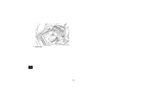
![YAMAHA YFZ450R 2013 Owners Manual 8-36
8hold the adjusting bolt with a wrench so
that it does not turn together with the lock-
nut.
[ECB00521]
WARNING
EWB02090Operating with improperly serviced or adjust-
ed brakes could cause the br YAMAHA YFZ450R 2013 Owners Manual 8-36
8hold the adjusting bolt with a wrench so
that it does not turn together with the lock-
nut.
[ECB00521]
WARNING
EWB02090Operating with improperly serviced or adjust-
ed brakes could cause the br](/manual-img/51/53846/w960_53846-123.png)
8-36
8hold the adjusting bolt with a wrench so
that it does not turn together with the lock-
nut.
[ECB00521]
WARNING
EWB02090Operating with improperly serviced or adjust-
ed brakes could cause the brakes to malfunc-
tion, resulting in reduced braking
performance. This could increase the chance
of a collision or accident. After adjusting the
parking brake free play, block the rear of the
ATV off the ground and spin the rear wheels.
Check to make sure there is no brake drag. If
brake drag is noticed, perform the adjustment
again.EBU24743Brake light switches The brake light, which is activated by the brake
pedal and brake lever, should come on just before
braking takes effect. The brake light switch for the brake pedal can be
adjusted as follows, but the front brake light switch
should be adjusted by a Yamaha dealer.
Turn the rear brake light switch adjusting nut while
holding the brake light switch in place. To make the
brake light come on earlier, turn the adjusting nut
in direction (a). To make the brake light come on
later, turn the adjusting nut in direction (b).
EBU30152Adjusting the clutch lever free play The clutch lever free play must be checked and, if
necessary, adjusted at the intervals specified in the
periodic maintenance and lubrication chart.
Tightening torque:
Locknut (rear brake caliper):16 Nm (1.6 m·kgf, 12 ft·lbf)1. Rear brake light switch
2. Rear brake light switch adjusting nut
1
2(a) (b)
U18P67E0.book Page 36 Wednesday, May 9, 2012 3:30 PM
Page 125 of 156

8-37
8
The clutch lever free play should measure 8.0–
13.0 mm (0.31–0.51 in) as shown. If the free play
is incorrect, adjust it as follows.
1. To increase the clutch lever free play, turn the clutch lever free play adjusting nut at the
clutch lever in direction (a), and to decrease it,
turn the nut in direction (b).
If the specified free play cannot be obtained,
proceed with the following steps.
2. Fully turn the adjusting nut at the clutch lever in direction (a) to loosen the clutch cable.
3. Slide the rubber cover back.
4. Loosen the locknut. 5. To increase the clutch lever free play, turn the
clutch lever free play adjusting nut located to-
wards the center of the cable in direction (a),
and to decrease it, turn the nut in direction (b).
6. Tighten the locknut.
7. Slide the rubber cover to its original position.
TIPIf the specified free play cannot be obtained as de-
scribed above or if the clutch does not operate cor-
rectly, have a Yamaha dealer check the internal
clutch mechanism.
1. Clutch lever free play
2. Clutch lever free play adjusting nut (clutch lever)
1 (a)
(b)
2
1. Locknut
2. Clutch lever free play adjusting nut (clutch cable)
3. Rubber cover
(a)
(b)
1
2
3
U18P67E0.book Page 37 Wednesday, May 9, 2012 3:30 PM
Page 126 of 156
8-38
8
EBU26864Drive chain slack The drive chain slack should be checked before
each ride and adjusted if necessary.
To check the drive chain slack1. Place the ATV on a level surface.TIPWhen checking and adjusting the drive chain
slack, there should be no weight on the ATV and
all tires must be touching the ground.2. Move the ATV back and forth to locate the tightest portion of the drive chain, and then
measure the drive chain slack as shown. 3. If the drive chain slack is incorrect, adjust it as
follows.
To adjust the drive chain slack 1. Place the ATV on a level surface.
2. Loosen the rear wheel axle pinch bolts.
3. Insert a rod of a diameter of 8 mm (0.3 in) and a length of 10 cm (4 in) into one of the holes in
the drive chain tensioner as shown.
Drive chain slack:
25.0–35.0 mm (0.98–1.38 in)
1. Drive chain slack
1
U18P67E0.book Page 38 Wednesday, May 9, 2012 3:30 PM
Page 127 of 156
8-39
8
TIPA rod can be obtained at a Yamaha dealer to make
this adjustment.4. Shift the transmission into neutral.
5. To tighten the drive chain, push the ATV back-ward. To loosen the drive chain, push the ATV
forward. NOTICE: Improper drive chain
slack will overload the engine as well as
other vital parts of the ATV and can lead to
drive chain slippage or breakage. To pre- vent this from occurring, keep the drive
chain slack within the specified limits.
[ECB00542]
6. Pull the rod out, and then tighten the rear axle
pinch bolts to the specified torque in the order
shown.
1. Rear wheel axle pinch bolt
2. Rod
3. Drive chain tensioner
4. Hole
3
4
2 11
Tightening torque:
Rear axle pinch bolt:21 Nm (2.1 m·kgf, 15 ft·lbf)
3 1 2
4
U18P67E0.book Page 39 Wednesday, May 9, 2012 3:30 PM
Page 128 of 156

8-40
8
EBU24882Lubricating the drive chain The drive chain must be cleaned and lubricated at
the intervals specified in the periodic maintenance
and lubrication chart, otherwise it will quickly wear
out, especially when riding in dusty or wet areas.
Service the drive chain as follows.NOTICEECB00561The drive chain must be lubricated after wash-
ing the ATV or riding in the rain or wet areas.1. Clean the drive chain with kerosene and asmall soft brush. NOTICE: To prevent dam-
aging the O-rings, do not clean the drive
chain with steam cleaners, high-pressure
washers or inappropriate solvents.
[ECB00571]
2. Wipe the drive chain dry.
3. Thoroughly lubricate the drive chain with a special O-ring chain lubricant. NOTICE: Do
not use engine oil or any other lubricants
for the drive chain, as they may contain
substances that could damage the O-
rings.
[ECB00581]
EBU24902
Checking and lubric ating the cables The operation and the condition of all control ca-
bles should be checked before each ride, and the
cables and cable ends should be lubricated if nec-1. O-rings
1
1
U18P67E0.book Page 40 Wednesday, May 9, 2012 3:30 PM