Page 41 of 76
 (3500 mi) (7000 mi) (10500 mi) (14000 mi)
�")
PERIODIC MAINTENANCE AND ADJUSTMENT
6-4
6
ODOMETER READING
CHECK OR ANNUAL
NO. ITEM MAINTENANCE JOB
1000 km 6000 km 12000 km 18000 km 24000 kmCHECK
(600 mi) (3500 mi) (7000 mi) (10500 mi) (14000 mi)
• Check coolant level and vehicle
19 *Cooling system
for coolant leakage.√√√ √√(CS50Z)
• Change. Every 3 years
20Final transmission • Check vehicle for oil leakage.
oil• Change.√√ √√ √ √
21 *V-belt• Replace. Every 10000 km (6000 mi)
22 *Front and rear
brake switches• Check operation.√√ √√ √ √
23Moving parts
and cables• Lubricate.√√√ √√
• Check operation and free play.
Throttle grip• Adjust the throttle cable free play
24 * if necessary.√√√ √√
housing and cable
• Lubricate the throttle grip
housing and cable.
25 *Lights, signals and • Check operation.
switches• Adjust headlight beam.√√ √√ √ √
EAUM2070
TIP
●The air filter needs more frequent service if you are riding in unusually wet or dusty areas.
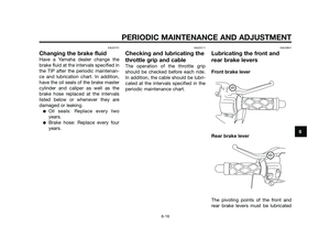
●Hydraulic brake service
• Regularly check and, if necessary, correct the brake fluid level.
• Every two years change the brake fluid.
• Replace the brake hoses every four years and if cracked or damaged.
Page 42 of 76
EAU18740
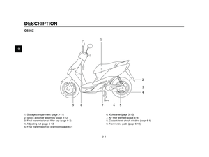
Removing and installing the
cowling and panel
1. Cowling A
1. Panel A
The cowling and panel shown above
need to be removed to perform some
of the maintenance jobs described in
this chapter. Refer to this section
each time a cowling or panel needs to
be removed and installed.
EAUS1520
Cowling A
To remove the cowling
1. Remove the screws, and then
pull the cowling off as shown.
1. Cowling 2. Screw
2. Disconnect the headlight lead
connectors, the turn signal cou-
plers, and the auxiliary light cou-
plers.
1. Headlight lead connector 2. Auxiliary light coupler3. Turn signal coupler
To install the cowling
1. Connect the headlight leads con-
nectors, the turn signal couplers,
and the auxiliary light couplers.
2. Place the cowling in the original
position, and then install the
screws.
GGYYBB
1
2
3
21
1
1
PERIODIC MAINTENANCE AND ADJUSTMENT
6-5
6
Page 43 of 76
.
2. Remove the screw, and then take
the panel off.
1. Screw
2. Panel A
To install the panel
1. Place the panel i")
EAUM1250
Panel A
T
o remove the panel
1. Open the storage compartment.
(See page 3-11).
2. Remove the screw, and then take
the panel off.
1. Screw
2. Panel A
To install the panel
1. Place the panel in the original
position, and then install the
screw.
2. Close the storage compartment.
EAU19622
Checking the spark plug
The spark plug is an important engine
component, which should be chec-
ked periodically, preferably by a
Yamaha dealer. Since heat and depo-
sits will cause any spark plug to
slowly erode, it should be removed
and checked in accordance with the
periodic maintenance and lubrication
chart. In addition, the condition of the
spark plug can reveal the condition of
the engine.
The porcelain insulator around the
center electrode of the spark plug
should be a medium-to-light tan (the
ideal color when the vehicle is ridden
normally). If the spark plug shows a
distinctly different color, the engine
could be operating improperly. Do not
attempt to diagnose such problems
yourself. Instead, have a Yamaha
dealer check the vehicle.
If the spark plug shows signs of elec-
trode erosion and excessive carbon
or other deposits, it should be repla-
ced.Before installing a spark plug, the
spark plug gap should be measured
with a wire thickness gauge and, if
necessary, adjusted to specification.
1. Spark plug gap
Clean the surface of the spark plug
gasket and its mating surface, and
then wipe off any grime from the
spark plug threads.
Spark plug gap:
0.6–0.7 mm (0.024–0.028 in)
1
ZAUM0037
Specified spark plug:
NBR8HS/NGK (for CS50 CS50Z)
BPR4HS/NGK (for CS50M)
1
2
PERIODIC MAINTENANCE AND ADJUSTMENT
6-6
6
Page 44 of 76

TIP
If a torque wrench is not available
when installing a spark plug, a good
estimate of the correct torque is
1/4–1/2 turn past finger tight. Howe-
ver, the spark plug should be tighte-
ned to the specified torque as soon
as possible.
EAU20064
Final transmission oil
The final transmission case must be
checked for oil leakage before each
ride. If any leakage is found, have a
Yamaha dealer check and repair the
scooter. In addition, the final trans-
mission oil must be changed as
follows at the intervals specified in the
periodic maintenance and lubrication
chart.
1. Start the engine, warm up the
final transmission oil by riding the
scooter for several minutes, and
then stop the engine.
2. Place the scooter on the centers-
tand.
3. Place an oil pan under the final
transmission case to collect the
used oil.
4. Remove the final transmission oil
filler cap and final transmission
drain bolt to drain the oil from the
final transmission case.
1. Final transmission oil filler cap
5. Install the final transmission oil
drain bolt, and then tighten it to
the specified torque.
1. Final transmission oil drain bolt
1
1
11Tightening torque:
Spark plug:
20 Nm (2.0 m•kgf, 14.5 ft•lbf)
PERIODIC MAINTENANCE AND ADJUSTMENT
6-7
6
Page 45 of 76

6. Refill with the specified amount
of the recommended final trans-
mission oil, and then install and
tighten the oil filler cap. WAR-
NING! Make sure that no
foreign material enters the final
transmission case. Make sure
that no oil gets on the tire or
wheel.
[EWA11311]
7. Check the final transmission case
for oil leakage. If oil is leaking,
check for the cause.
EAUS1200
Coolant (CS50Z)
The coolant level should be checked
before each ride. In addition, the coo-
lant must be changed at the intervals
specified in the periodic maintenance
and lubrication chart.
EAUM2102
To check the coolant level
1. Place the vehicle on a level surfa-
ce and hold it in an upright posi-
tion.
TIP
●The coolant level must be chec-
ked on a cold engine since the
level varies with engine tempera-
ture.
●Make sure that the vehicle is
positioned straight up when
checking the coolant level. A
slight tilt to the side can result in
a false reading.
2. Check the coolant level through
the check window.
TIP
The coolant should be between the
minimum and maximum level marks.
1. Coolant level check window
2. Maximum level mark
3. Minimum level mark
3. If the coolant is at or below the
minimum level mark, remove the
cowling A. (See page 6-5).
4. Open the reservoir cap, and then
add coolant to the maximum
level mark. WARNING! Remove
only the coolant reservoir cap.
Never attempt to remove the
radiator cap when the engine is
hot.
[EWA15161]. NOTICE: If coolant
is not available, use distilled
MAX
MIN2
3
1
Recommended final transmission
oil:
See page 8-1
Oil quantity:
0.11 L (0.12 US qt, 0.10 Imp.qt)
Tightening torque:
Final transmission oil drain bolt:
18 Nm (1.8 m•kgf, 13.0 ft•lbf)
PERIODIC MAINTENANCE AND ADJUSTMENT
6-8
6
Page 46 of 76

water or soft tap water instead.
Do not use hard water or salt
water since it is harmful to the
engine. If water has been used
instead of coolant, replace it
with coolant as soon as possi-
ble, otherwise the cooling sys-
tem will not be protected
against frost and corrosion. If
water has been added to the
coolant, have a Yamaha dealer
check the antifreeze content of
the coolant as soon as possi-
ble, otherwise the effective-
ness of the coolant will be
reduced.
[ECA10472]
1. Coolant reservoir cap
2. Maximum level mark
3. Minimum level mark
5. Close the reservoir cap, and then
install the cowling.
EAU33031
Changing the coolant
The coolant must be changed at the
intervals specified in the periodic
maintenance and lubrication chart.
Have a Yamaha dealer change the
coolant. WARNING! Never attempt
to remove the radiator cap when
the engine is hot.
[EWA10381]EAU40370
Air filter element
The air filter element must be cleaned
and replaced at the intervals specified
in the periodic maintenance and lubri-
cation chart. Have a Yamaha dealer
clean and replace the air filter ele-
ment.
Coolant reservoir capacity:
0.25 L (0.26 US qt, 0.22 Imp.qt)
1
2
3FULL
LOW
PERIODIC MAINTENANCE AND ADJUSTMENT
6-9
6
Page 47 of 76
EAU21300
Adjusting the carburetor
The carburetor is an important part of
the engine and requires very sophisti-
cated adjustment. Therefore, all car-
buretor adjustments should be left to
a Yamaha dealer, who has the neces-
sary professional knowledge and
experience.
EAU21370
Adjusting the throttle cable
free play
1. Throttle cable free play
The throttle cable free play should
measure 2.0–5.0 mm (0.08–0.20 in) at
the throttle grip. Periodically check
the throttle cable free play and, if
necessary, adjust it as follows.
TIP
The engine idling speed must be
correctly adjusted before checking
and adjusting the throttle cable free
play.
1. Loosen the locknut.2. To increase the throttle cable free
play, turn the adjusting nut in
direction (a). To decrease the
throttle cable free play, turn the
adjusting nut in direction (b).
1. Locknut
2. Adjusting nut
3. Tighten the locknut.
1
2
a
b
1
PERIODIC MAINTENANCE AND ADJUSTMENT
6-10
6
Page 48 of 76

EAU33601
Tires
To maximize the performance, durabi-
lity, and safe operation of your vehi-
cle, note the following points regar-
ding the specified tires.
Tire air pressure
The tire air pressure should be chec-
ked and, if necessary, adjusted befo-
re each ride.
EWA10501
sWARNING
Operation of this vehicle with
improper tire pressure may cause
severe injury or death from loss of
control.
●The tire air pressure must be
checked and adjusted on cold
tires (i.e., when the temperatu-re of the tires equals the
ambient temperature).
●The tire air pressure must be
adjusted in accordance with
the riding speed and with the
total weight of rider, passenger,
cargo, and accessories appro-
ved for this model.
EWA10511
sWARNING
Never overload your vehicle. Ope-
ration of an overloaded vehicle
could cause an accident.
Tire inspection
1. Tire wear indicator
2. Tire sidewall
The tires must be checked before
each ride. If the center tread depth
reaches the specified limit, if the tire
has a nail or glass fragments in it, or if
the sidewall is cracked, have a Yama-
ha dealer replace the tire immediately.
1
2
ZAUM0054
Tire air pressure (measured on
cold tires):
0–90 kg (0–198 lb):
Front:
175 kPa (1.75 kgf/cm
2, 25 psi,
1.75 bar)
Rear:
200 kPa (2.00 kgf/cm
2, 29 psi,
2.00 bar)
90 kg (198 lb) - maximum load:
Front:
175 kPa (1.75 kgf/cm
2, 25 psi,
1.75 bar)
Rear:
225 kPa (2.25 kgf/cm
2, 33 psi,
2.25 bar)
Maximum load*:
CS50/CS50M 169 kg (373 lb)
CS50Z 166 kg (366 lb)
* Total weight of rider, passenger,
cargo and accessories
ZAUM0053
PERIODIC MAINTENANCE AND ADJUSTMENT
6-11
6