Page 17 of 76
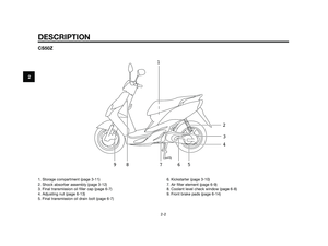
DESCRIPTION
2-5
2
1. Rear brake lever (page 3-7)
2. Left handlebar switches (page 3-6)
3. Speedometer (page 3-3)
4. Multi-function display (page 3-4)5. Main switch/steering lock (page 3-1)
6. Right handlebar switch (page 3-6)
7. Throttle grip (page 6-10)
8. Front brake lever (page 3-6)
EAU32240
Controls and instruments
CS50/CS50M/CS50Z
1
234
5
678
Page 18 of 76

INSTRUMENT AND CONTROL FUNCTIONS
3-1
3
EAU10460
Main switch/steering lock
The main switch/steering lock con-
trols the ignition and lighting systems,
and is used to lock the steering. The
various positions are described
below.
EAU10640
“” ON
All electrical circuits are supplied with
power, and the engine can be started.
The key cannot be removed.
TIP
The headlight, meter lighting and tai-
llight come on automatically when the
engine is started.
EAU10661
“” OFF
All electrical systems are off. The key
can be removed.
EWA10061
sWARNING
Never turn the key to “ ” or “ ”
while the vehicle is moving. Other-
wise the electrical systems will be
switched off, which may result in
loss of control or an accident.
EAU10670
The 2-stroke engine oil level warning
light should come on. (See page 3-2).
EAU10681
“ ” LOCK
The steering is locked, and all electri-
cal systems are off. The key can be
removed.T
o lock the steering
1. Push.
2. Turn.
1. Turn the handlebars all the way to
the left.
2. Push the key in from the “ ”
position, and then turn it to “ ”
while still pushing it.
3. Remove the key.
Page 19 of 76
To unlock the steering
1. Push.
2. Turn.
1. Push the key in, and then turn it
to “ ” while still pushing it.
EAU11003
Indicator and warning lights
1. Left turn signal indicator light “ ”
2. Oil level warning light “ ”
3. High beam indicator light “ ”
4. Right turn signal indicator light “ ”1. Left turn signal indicator light “ ”
2. Coolant temperature warning light “ ”
3. Oil level warning light “ ”
4. High beam indicator light “ ”
5. Right turn signal indicator light “ ”
EAU11030
Turn signal indicator lights “ ”
and “ ”
The corresponding indicator light flas-
hes when the turn signal switch is
pushed to the left or right.
EAU11080
High beam indicator light “ ”
This indicator light comes on when
the high beam of the headlight is swit-
ched on.
km/h
01020304050607080
14
3 25
CS50Z
km/h
01020304050607080
143 2
CS50/CS50M1
2
INSTRUMENT AND CONTROL FUNCTIONS
3-2
3
Page 20 of 76

EAU11181
Oil level warning light “ ”
This warning light comes on when the
key is in the “ ” position or if the oil
level in the 2-stroke engine oil tank is
low during operation. If the warning
light comes on during operation, stop
immediately and fill the oil tank with
Yamalube 2 or equivalent 2-stroke
engine oil of either JASO grade “FC”
or ISO grades “EG-C” or “EG-D”. The
warning light should go off after the 2-
stroke engine oil tank has been refi-
lled.
TIP
If the warning light does not come on
when the key is in the “ ” position
or does not go off after the 2-stroke
engine oil tank has been refilled, have
a Yamaha dealer check the electrical
circuit.
ECA16291
NOTICE
Do not operate the vehicle until you
know that the engine oil level is suf-
ficient.
EAUS1530
Speedometer
1. Speedometer
1. Speedometer
1. Speedometer
1. Speedometer
The speedometer shows the riding
speed.
k m/hmph
0
10
203040
50
01020304050 6 0 7 0 8 0
1
CS50Z (for UK only)
k m/hmph
0
10
203040
50
01020304050 6 0 7 0 8 0
1
CS50/CS50M (for UK only)
k m/h
010
20
30405060
70
80
1
CS50Z
k m/h
010
20
30405060
70
80
1
CS50/CS50M
INSTRUMENT AND CONTROL FUNCTIONS
3-3
3
Page 21 of 76

EAUS1424
Multi-function display
1. Select button
2. Odometer/tripmeter
3. Clock
4. Fuel meter
EWA12312
sWARNING
Be sure to stop the vehicle before
making any setting changes to the
multi-function display. Changing
settings while riding can distract
the operator and increase the risk
of an accident.
The multi-function display is equip-
ped with the following:
●a digital clock
●an odometer (which shows the
total distance traveled)
●a tripmeter (which shows the dis-
tance traveled since it was last
set to zero)
●a fuel gauge
●a self-diagnosis device
●a function button (which selects,
sets and resets various modes of
the multi-function display)
TIP
●Be sure to turn the key to “ ”
before using the button.
●For the U.K. only: The odometer
and tripmeter are displayed in
miles.
To set the clock:
1. Select the odometer and push
the button for at least two
seconds.
2. When the hour digits start flas-
hing, push the button to set the
hours.3. To change the ten-minute digit,
push the button for at least two
seconds.
4. When the ten-minute digit starts
flashing, push the button to set it.
5. To change the one-minute digit,
push the button for at least two
seconds.
km/h
01020304050607080
1
43 2
INSTRUMENT AND CONTROL FUNCTIONS
3-4
3
Page 22 of 76

6. When the one-minute digit starts
flashing, push the button to set it.
7. Push the button for at least two
seconds to start the clock.
TIP
After setting the clock, be sure to
push the button for at least two
seconds before turning the key to
“ ”, otherwise the clock will not be
set.
Odometer and tripmeter modes
Pushing the button switches the dis-
play between the odometer mode
“ODO” and the tripmeter “TRIP” in
the following order:
ODO �TRIP �ODO
1. Odometer
2. Tripmeter
To reset the tripmeter, select it by
pushing the button, and then push it
again for at least two seconds.
Fuel gauge
The fuel gauge indicates the amount
of fuel in the fuel tank. The display
segments of the fuel gauge disappear
towards “E” (Empty) as the fuel level
decreases. When only one segment is
left near “E”, refuel as soon as possi-
ble.
Self-diagnosis device
This model is equipped with a self-
diagnosis device for the fuel electrical
circuit.
If a problem is detected in the fuel
electrical circuit, all LCD segments ofthe fuel gauge will flash. If this occurs,
have a Yamaha dealer check the vehi-
cle.
PRESS
BUTTON
PRESS
BUTTON
INSTRUMENT AND CONTROL FUNCTIONS
3-5
3
Page 23 of 76

EAU12347
Handlebar switches
Left
1. Dimmer switch “ / ”
2. Turn signal switch “ / ”
3. Horn switch “ ”
Right
1. Start switch “ ”
EAU12400
Dimmer switch “ / ”
Set this switch to “ ” for the high
beam and to “ ” for the low beam.
EAU12460
Turn signal switch “ / ”
To signal a right-hand turn, push this
switch to “ ”. To signal a left-hand
turn, push this switch to “ ”. When
released, the switch returns to the
center position. To cancel the turn
signal lights, push the switch in after it
has returned to the center position.
EAU12500
Horn switch “ ”
Press this switch to sound the horn.
EAUM1132
Start switch “ ”
Push this switch while applying the
front or rear brake to crank the engine
with the starter. See page 5-1 for star-
ting instructions prior to starting the
engine.
EAU12900
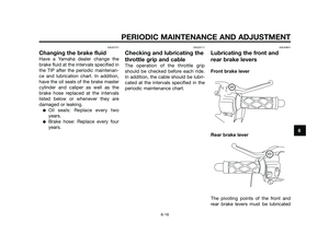
Front brake lever
1. Front brake lever
The front brake lever is located on the
right handlebar grip. To apply the
front brake, pull this lever toward the
handlebar grip.
1
1
1
2
3
INSTRUMENT AND CONTROL FUNCTIONS
3-6
3
Page 24 of 76
EAU12950
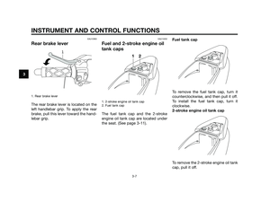
Rear brake lever
1. Rear brake lever
The rear brake lever is located on the
left handlebar grip. To apply the rear
brake, pull this lever toward the hand-
lebar grip.
EAU13202
Fuel and 2-stroke engine oil
tank caps
1. 2-stroke engine oil tank cap
2. Fuel tank cap
The fuel tank cap and the 2-stroke
engine oil tank cap are located under
the seat. (See page 3-11). Fuel tank cap
To remove the fuel tank cap, turn it
counterclockwise, and then pull it off.
To install the fuel tank cap, turn it
clockwise.
2-stroke engine oil tank cap
To remove the 2-stroke engine oil tank
cap, pull it off.
1
2
1
INSTRUMENT AND CONTROL FUNCTIONS
3-7
3


2. Left handlebar switches (page 3-6)
3. Speedometer (page 3-3)
4. Multi-function display (page 3-4)5. Main switch/steering lock (page 3-1)
6. Right ha")

