Page 57 of 118

INSTRUMENT AND CONTROL FUNCTIONS
3-42
3
TIPTo obtain a precise adjustment, it is ad-
visable to check the actual total number
of clicks or turns of the damping force
adjusting mechanism. This adjustment
range may not exactly match the spec-
ifications listed due to small differences
in production.
WARNING
EWA10221
This shock absorber assembly con-
tains highly pressurized nitrogen
gas. Read and understand the fol-
lowing information before handling
the shock absorber assembly.●
Do not tamper with or attempt to
open the cylinder assembly.
●
Do not subject the shock ab-
sorber assembly to an open
flame or other high heat source.
This may cause the unit to ex-
plode due to excessive gas
pressure.
●
Do not deform or damage the
cylinder in any way. Cylinder
damage will result in poor
damping performance.
●
Do not dispose of a damaged or
worn-out shock absorber as-
sembly yourself. Take the shock
absorber assembly to a Yamaha
dealer for any service.
EAU15305
Sidestand The sidestand is located on the left side
of the frame. Raise the sidestand or
lower it with your foot while holding the
vehicle upright.TIPThe built-in sidestand switch is part of
the ignition circuit cut-off system, which
cuts the ignition in certain situations.
(See the following section for an expla-
nation of the ignition circuit cut-off sys-
tem.)
WARNING
EWA10241
The vehicle must not be ridden with
the sidestand down, or if the side-
stand cannot be properly moved up
(or does not stay up), otherwise the
sidestand could contact the ground
and distract the operator, resulting
in a possible loss of control.
Yamaha’s ignition circuit cut-off
system has been designed to assist
the operator in fulfilling the respon-
sibility of raising the sidestand be-
fore starting off. Therefore, check
1. Rebound damping force adjusting knobRebound damping setting:Minimum (soft):20 click(s) in direction (b)*
Standard: 12 click(s) in direction (b)*
Maximum (hard):
3 click(s) in direction (b)*
* With the adjusting knob fully turned in direction (a)
U1MCE0E0.book Page 42 Thursday, July 19, 2012 6:59 PM
Page 58 of 118
INSTRUMENT AND CONTROL FUNCTIONS
3-43
3this system regularly and have a
Yamaha dealer repair it if it does not function properly.
EAU54490
Ignition circuit cut-off system The ignition circuit cut-off system (com-
prising the sidestand switch, clutch
switch and neutral switch) has the fol-
lowing functions.●
It prevents starting when the trans-
mission is in gear and the side-
stand is up, but the clutch lever is
not pulled.
●
It prevents starting when the trans-
mission is in gear and the clutch le-
ver is pulled, but the sidestand is
still down.
●
It cuts the running engine when the
transmission is in gear and the
sidestand is moved down.
Periodically check the operation of the
ignition circuit cut-off system according
to the following procedure.
U1MCE0E0.book Page 43 Thursday, July 19, 2012 6:59 PM
Page 59 of 118

INSTRUMENT AND CONTROL FUNCTIONS
3-44
3
With the engine turned off:
1. Move the sidestand down.
2. Make sure that the start/engine stop switch is set to “ ”.
3. Turn the key on.
4. Shift the transmission into the neutral position.
5. Push the “ ” side of the start/engine stop switch.
Does the engine start?
With the engine still running:
6. Move the sidestand up.
7. Keep the clutch lever pulled.
8. Shift the transmission into gear.
9. Move the sidestand down.
Does the engine stall?
After the engine has stalled:
10. Move the sidestand up.
11. Keep the clutch lever pulled.
12. Push the “ ” side of the start/engine stop switch.
Does the engine start?
The system is OK. The motorcycle can be ridden.
YES NO YES NO YES NO
The neutral switch may not be working correctly.
The motorcycle should not be ridden until
checked by a Yamaha dealer.
The clutch switch may not be working correctly.
The motorcycle should not be ridden until
checked by a Yamaha dealer.The sidestand switch may not be working correctly.
The motorcycle should not be ridden until
checked by a Yamaha dealer. The vehicle must be placed on the center-
stand during this inspection.If a malfunction is noted, have a Yamaha
dealer check the system before riding.
WA R N I N G
U1MCE0E0.book Page 44 Thursday, July 19, 2012 6:59 PM
Page 60 of 118

INSTRUMENT AND CONTROL FUNCTIONS
3-45
3
EAU39655
Auxiliary DC jack
WARNING
EWA14360
To prevent electrical shock or short-
circuiting, make sure that the cap is
installed when the auxiliary DC jack
is not being used.NOTICE
ECA15431
The accessory connected to the
auxiliary DC jack should not be used
with the engine turned off, and the
load must never exceed 30 W (2.5 A),
otherwise the fuse may blow or the
battery may discharge.This vehicle is equipped with an auxilia-
ry DC jack in the accessory box.
A 12-V accessory connected to the
auxiliary jack can be used when the key
is in the “ON” position and should only
be used when the engine is running.
To use the auxiliary DC jack1. Open the accessory box lid. (See page 3-36.)
2. Turn the key to “OFF”.
3. Remove the auxiliary DC jack cap. 4. Turn the accessory off.
5. Insert the accessory plug into the
auxiliary DC jack.
6. Turn the key to “ON”, and then start the engine. (See page 5-1.)
7. Turn the accessory on.
1. Auxiliary DC jack cap
1. Auxiliary DC jack
11
U1MCE0E0.book Page 45 Thursday, July 19, 2012 6:59 PM
Page 61 of 118

FOR YOUR SAFETY – PRE-OPERATION CHECKS
4-1
4
EAU15596
Inspect your vehicle each time you use it to make sure the vehicle is in safe operating condition. Always follow the inspection
and maintenance procedures and schedules described in the Owner’s Manual.
WARNING
EWA11151
Failure to inspect or maintain the vehicle properly increases the possibility of an accident or equipment damage.
Do not operate the vehicle if you find any problem. If a problem cannot be corrected by the procedures provided in
this manual, have the vehicle inspected by a Yamaha dealer.Before using this vehicle, check the following points:
ITEMCHECKS PAGE
Fuel Check fuel level in fuel tank.
Refuel if necessary.
Check fuel line for leakage.
Check fuel tank breather/overflow hose for obstructions, cracks or damage, and
check hose connection. 3-30, 3-31
Engine oil Check oil level in engine.
If necessary, add recommended oil to specified level.
Check vehicle for oil leakage. 6-12
Final gear oil Check vehicle for oil leakage. 6-14
Coolant Check coolant level in reservoir.
If necessary, add recommended coolant to specified level.
Check cooling system for leakage. 6-16
Front brake Check operation.
If soft or spongy, have Yamaha dealer bleed hydraulic system.
Check brake pads for wear.
Replace if necessary.
Check fluid level in reservoir.
If necessary, add specified brake fluid to specified level.
Check hydraulic system for leakage. 6-24, 6-24
U1MCE0E0.book Page 1 Thursday, July 19, 2012 6:59 PM
Page 62 of 118

FOR YOUR SAFETY – PRE-OPERATION CHECKS
4-2
4
Rear brake Check operation.
If soft or spongy, have Yamaha dealer bleed hydraulic system.
Check brake pads for wear.
Replace if necessary.
Check fluid level in reservoir.
If necessary, add specified brake fluid to specified level.
Check hydraulic system for leakage. 6-24, 6-24
Clutch Check operation.
If soft or spongy, have Yamaha dealer bleed hydraulic system.
Check fluid level in reservoir.
If necessary, add specified brake fluid to specified level.
Check hydraulic system for leakage. 6-22, 6-24
Throttle grip Make sure that operation is smooth.
Check throttle grip free play.
If necessary, have Yamaha dealer adjust throttle grip free play and lubricate cable
and grip housing. 6-19, 6-26
Control cables Make sure that operation is smooth.
Lubricate if necessary. 6-26
Wheels and tires Check for damage.
Check tire condition and tread depth.
Check air pressure.
Correct if necessary.
6-19, 6-22
Brake and shift pedals Make sure that operation is smooth.
Lubricate pedal pivoting points if necessary.
6-27
Brake and clutch levers Make sure that operation is smooth.
Lubricate lever pivoting points if necessary. 6-27
Centerstand, sidestand Make sure that operation is smooth.
Lubricate pivots if necessary.
6-28
Chassis fasteners Make sure that all nuts, bolts and screws are properly tightened.
Tighten if necessary.
—
ITEM CHECKS PAGE
U1MCE0E0.book Page 2 Thursday, July 19, 2012 6:59 PM
Page 63 of 118
FOR YOUR SAFETY – PRE-OPERATION CHECKS
4-3
4
Instruments, lights, signals
and switches Check operation.
Correct if necessary.
—
Sidestand switch Check operation of ignition circuit cut-off system.
If system is not working correctly, have Yamaha dealer check vehicle.
3-42
ITEM CHECKS PAGE
U1MCE0E0.book Page 3 Thursday, July 19, 2012 6:59 PM
Page 64 of 118

OPERATION AND IMPORTANT RIDING POINTS
5-1
5
EAU15951
Read the Owner’s Manual carefully to
become familiar with all controls. If
there is a control or function you do not
understand, ask your Yamaha dealer.
WARNING
EWA10271
Failure to familiarize yourself with
the controls can lead to loss of con-
trol, which could cause an accident
or injury.
EAU47150
TIPThis model is equipped with:●
a lean angle sensor to stop the en-
gine in case of a turnover. In this
case, the multi-function meter unit
indicates error code 30, but this is
not a malfunction. Turn the key to
“OFF” and then to “ON” to clear the
error code. Failing to do so will pre-
vent the engine from starting even
though the engine will crank when
pushing the start switch.
●
an engine auto-stop system. The
engine stops automatically if left
idling for 20 minutes. In this case,
the multi-function meter unit indi-
cates error code 70, but this is not
a malfunction. Push the start
switch to clear the error code and
to restart the engine.
EAU54170
Starting the engine In order for the ignition circuit cut-off
system to enable starting, one of the
following conditions must be met:●
The transmission is in the neutral
position.
●
The transmission is in gear with
the clutch lever pulled and the
sidestand up.
See page 3-43 for more informa-
tion.
1. Turn the key to “ON” and make sure that the start/engine stop
switch is set to “ ”.
The following warning lights and
indicator lights should come on for
a few seconds, then go off.●
Oil level warning light
●
Engine trouble warning light
●
Traction control system indi-
cator/warning light
●
Cruise control indicator lights
●
Immobilizer system indicator
light
U1MCE0E0.book Page 1 Thursday, July 19, 2012 6:59 PM
 1
1 2
2 3
3 4
4 5
5 6
6 7
7 8
8 9
9 10
10 11
11 12
12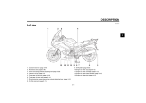 13
13 14
14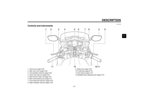 15
15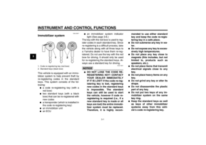 16
16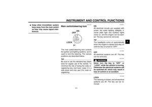 17
17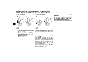 18
18 19
19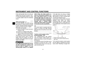 20
20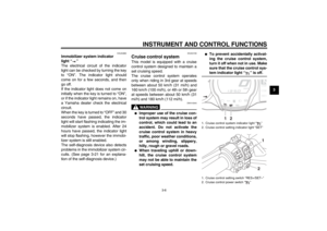 21
21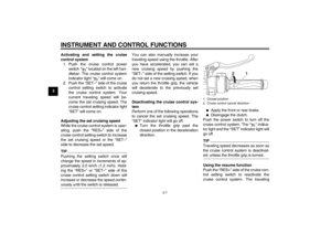 22
22 23
23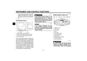 24
24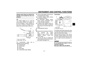 25
25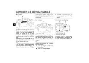 26
26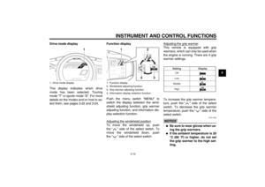 27
27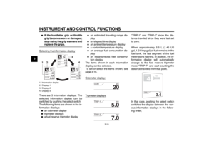 28
28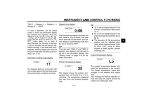 29
29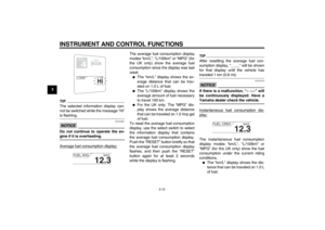 30
30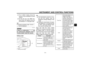 31
31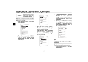 32
32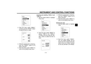 33
33 34
34 35
35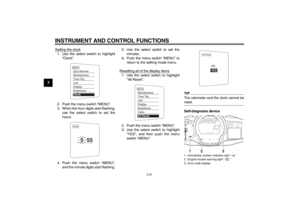 36
36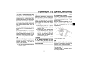 37
37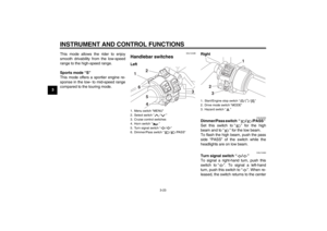 38
38 39
39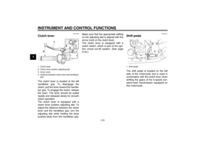 40
40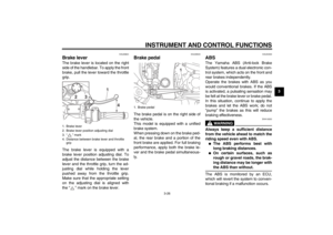 41
41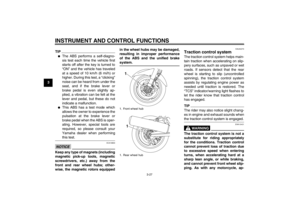 42
42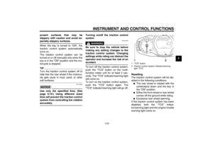 43
43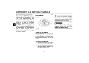 44
44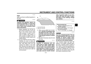 45
45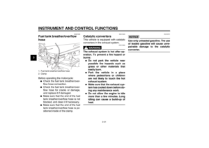 46
46 47
47 48
48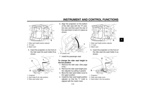 49
49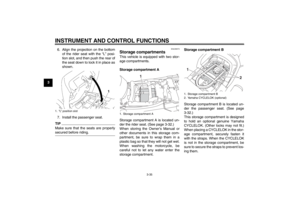 50
50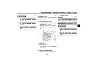 51
51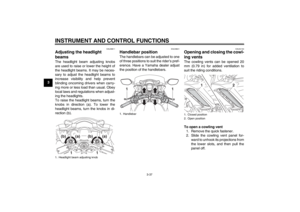 52
52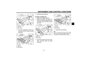 53
53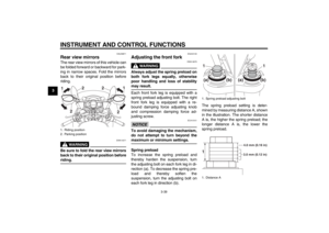 54
54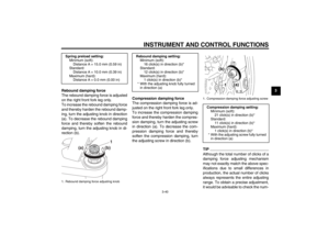 55
55 56
56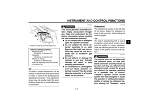 57
57 58
58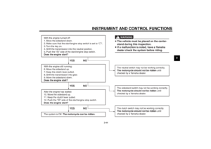 59
59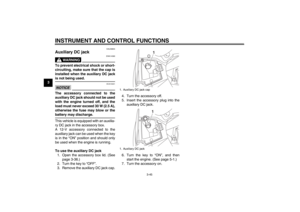 60
60 61
61 62
62 63
63 64
64 65
65 66
66 67
67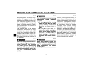 68
68 69
69 70
70 71
71 72
72 73
73 74
74 75
75 76
76 77
77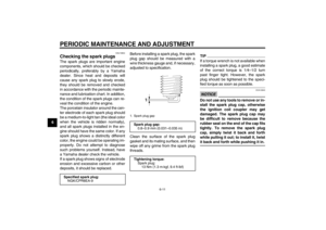 78
78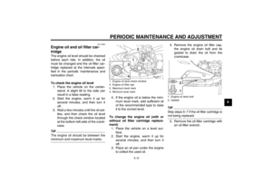 79
79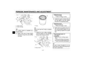 80
80 81
81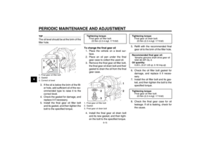 82
82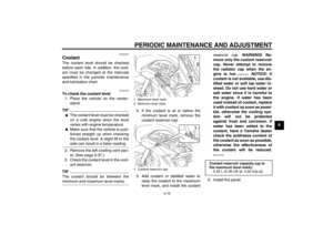 83
83 84
84 85
85 86
86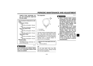 87
87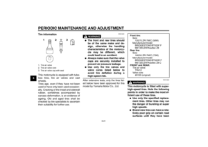 88
88 89
89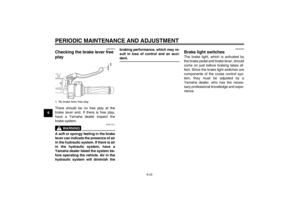 90
90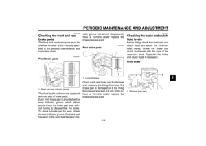 91
91 92
92 93
93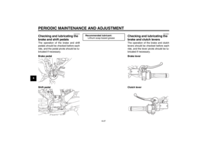 94
94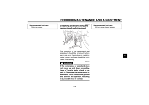 95
95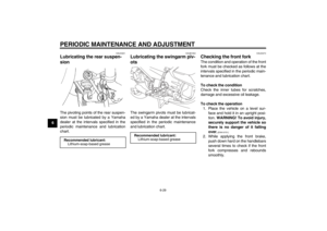 96
96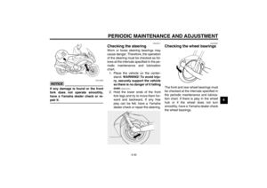 97
97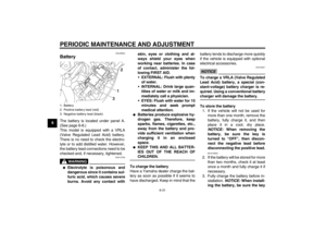 98
98 99
99 100
100 101
101 102
102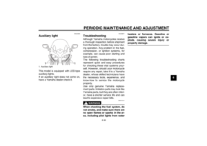 103
103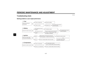 104
104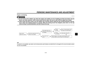 105
105 106
106 107
107 108
108 109
109 110
110 111
111 112
112 113
113 114
114 115
115 116
116 117
117
