Page 17 of 74

INSTRUMENT AND CONTROL FUNCTIONS
3-1
3
EAU10461
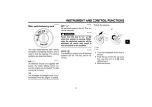
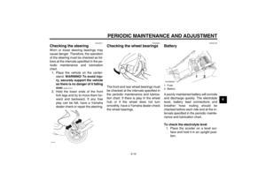
Main switch/steering lock The main switch/steering lock controls
the ignition and lighting systems, and is
used to lock the steering. The various
positions are described below.
EAUS1381
ON “ ”
All electrical circuits are supplied with
power, the meter lighting comes on,
and the engine can be started. The key
cannot be removed.TIPThe headlight and taillight come on au-
tomatically when the engine is started.
EAU10661
OFF “ ”
All electrical systems are off. The key
can be removed.
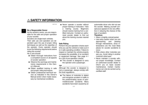
WARNING
EWA10061
Never turn the key to “ ” or “ ”
while the vehicle is moving. Other-
wise the electrical systems will be
switched off, which may result in
loss of control or an accident.
EAU10684
LOCK “ ”
The steering is locked, and all electrical
systems are off. The key can be re-
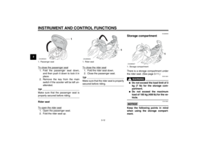
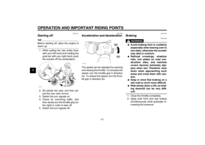
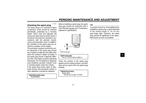
moved.To lock the steering
1. Turn the handlebars all the way to
the left.
2. Push the key in from the “ ” posi-
tion, and then turn it to “ ” while
still pushing it.
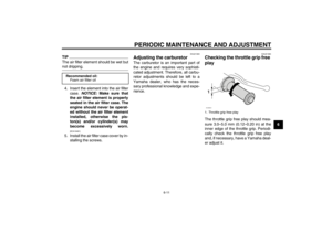
3. Remove the key.1. Push.
2. Turn.
U1PHE0E0.book Page 1 Wednesday, August 29, 2012 4:42 PM
Page 18 of 74

INSTRUMENT AND CONTROL FUNCTIONS
3-2
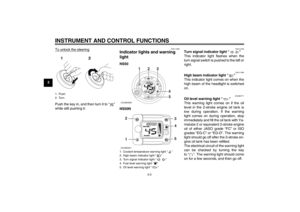
3To unlock the steering
Push the key in, and then turn it to “ ”
while still pushing it.
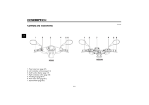
EAU11006
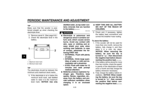
Indicator lights and warning
light NS50
NS50N
EAU11020
Turn signal indicator light “ ”
This indicator light flashes when the
turn signal switch is pushed to the left or
right.
EAU11080
High beam indicator light “ ”
This indicator light comes on when the
high beam of the headlight is switched
on.
EAUM2771
Oil level warning light “ ”
This warning light comes on if the oil
level in the 2-stroke engine oil tank is
low during operation. If the warning
light comes on during operation, stop
immediately and fill the oil tank with Ya-
malube 2 or equivalent 2-stroke engine
oil of either JASO grade “FC” or ISO
grades “EG-C” or “EG-D”. The warning
light should go off after the 2-stroke en-
gine oil tank has been refilled.
The electrical circuit of the warning light
can be checked by turning the key
to “ ”. The warning light should come
on for a few seconds, and then go off.
1. Push.
2. Turn.
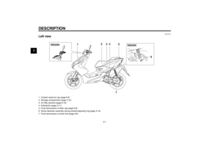
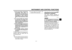
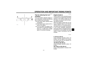
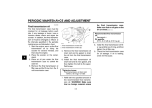
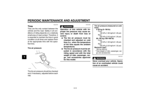
1. Coolant temperature warning light “ ”
2. High beam indicator light “ ”
3. Turn signal indicator light “ ”
4. Fuel level warning light “ ”
5. Oil level warning light “ ”ZAUM0908
12
3
4
5
ZAUM0957
3
45
2
1
U1PHE0E0.book Page 2 Wednesday, August 29, 2012 4:42 PM
Page 19 of 74

INSTRUMENT AND CONTROL FUNCTIONS
3-3
3
TIPIf the warning light does not come on
when the key is in the “ ” position or
does not go off after the 2-stroke en-
gine oil tank has been refilled, have a
Yamaha dealer check the electrical cir-
cuit.NOTICE
ECA16291
Do not operate the vehicle until you
know that the engine oil level is suf-
ficient.
EAUM2791
Fuel level warning light “ ”
This warning light comes on when the
fuel level drops below approximately
1.0 L (0.26 US gal, 0.22 Imp.gal). When
this occurs, refuel as soon as possible.
The electrical circuit of the warning light
can be checked by turning the key
to “ ”. The warning light should come
on for a few seconds, and then go off.
If the warning light does not come on
initially when the key is turned to “ ”,
or if the warning light remains on, have
a Yamaha dealer check the electrical
circuit.
EAUM2781
Coolant temperature warning
light “ ”
This warning light comes on if the en-
gine overheats. If this occurs, stop the
engine immediately and allow the en-
gine to cool.
The electrical circuit of the warning light
can be checked by turning the key
to “ ”. The warning light should come
on for a few seconds, and then go off.
If the warning light does not come on
initially when the key is turned to “ ”,
or if the warning light remains on, have
a Yamaha dealer check the electrical
circuit.NOTICE
ECA10021
Do not continue to operate the en-
gine if it is overheating.TIP●
For radiator-fan-equipped vehi-
cles, the radiator fan(s) automati-
cally switch on or off according to
the coolant temperature in the ra-
diator.
●
If the engine overheats, see page
6-27 for further instructions.
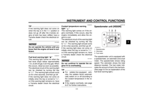
EAUM1590
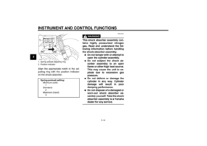
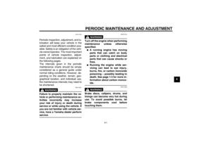
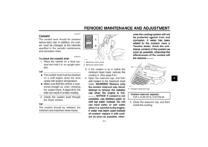
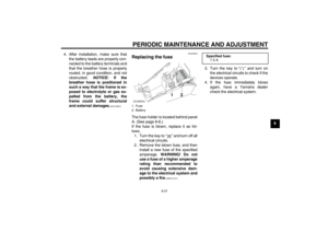
Speedometer unit (NS50N)The speedometer unit is equipped with
a speedometer, an odometer and a fuel
meter. The speedometer shows riding
speed. The odometer shows the total
distance traveled. The fuel meter indi-
cates the amount of fuel in the fuel tank.
(See page 3-2 for an explanation of the
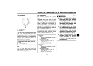
fuel level warning light.)1. Speedometer
2. Odometer
3. Fuel meterZAUM0910
1
2
3
U1PHE0E0.book Page 3 Wednesday, August 29, 2012 4:42 PM
Page 20 of 74
TIPThe multi-function display performs the
following self-test for three seconds in
order to check the electrical circuit.�")
INSTRUMENT AND CONTROL FUNCTIONS
3-4
3
EAUM2821
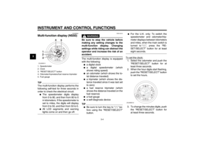
Multi-function display (NS50)TIPThe multi-function display performs the
following self-test for three seconds in
order to check the electrical circuit.●
The speedometer digits display
from 0 to 80, and then from 80 to 0
in kilometers. If the speedometer is
set to miles, the digits will display
from 0 to 50, and then from 50 to 0.
●
All LCD segments and warning
lights come on and then go off.
WARNING
EWA12312
Be sure to stop the vehicle before
making any setting changes to the
multi-function display. Changing
settings while riding can distract the
operator and increase the risk of an
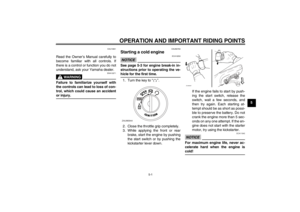
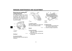
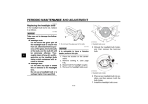
accident.The multi-function display is equipped
with the following:●
a digital clock
●
a digital speedometer (which
shows riding speed)
●
an odometer (which shows the to-
tal distance traveled)
●
a tripmeter (which shows the dis-
tance traveled since it was last set
to zero)
●
a fuel reserve tripmeter (which
shows the distance traveled on the
fuel reserve)
●
a fuel gauge
●
a self-diagnosis device
TIP●
Be sure to turn the key to “ ” be-
fore using the “RESET/SELECT”
button.
●
For the U.K. only: To switch the
speedometer and odometer/trip-
meter displays between kilometers
and miles, when the main switch is
turned to “ ”, press the “RE-
SET/SELECT” button for at least
eight seconds.
To set the clock:1. Select the odometer and push the
“RESET/SELECT” button for at
least three seconds.
2. When the hour digits start flashing,
push the “RESET/SELECT” button
to set the hours.
3. To change the minutes digits, push
the “RESET/SELECT” button for
at least three seconds.
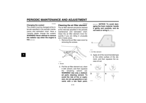
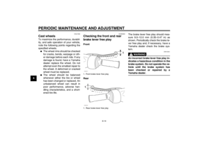
1. Speedometer
2. Clock
3. “RESET/SELECT” button
4. Odometer/tripmeters/fuel reserve tripmeter
5. Fuel gaugeZAUM0911
1
2
34
5
ZAUM0912
U1PHE0E0.book Page 4 Wednesday, August 29, 2012 4:42 PM
Page 21 of 74

INSTRUMENT AND CONTROL FUNCTIONS
3-5
3 4. When the minutes digits start
flashing, push the “RESET/SE-
LECT” button to set the minutes.
5. Push the “RESET/SELECT” but-
ton for at least three seconds to
start the clock.
TIPAfter setting the clock, be sure to push
the “RESET/SELECT” button for at
least three seconds before turning the
key to “ ”, otherwise the clock will not
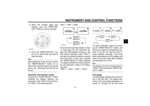
be set.Odometer and tripmeter modes
Pushing the “RESET/SELECT” button
switches the display between the
odometer mode “ODO” and the tripme-
ter “TRIP” in the following order:ODO → TRIP → ODO
If the fuel level warning indicator comes
on (see page 3-2), the odometer dis-
play will automatically change to the
fuel reserve tripmeter mode “TRIP F”
and start counting the distance traveled
from that point. In that case, pushing
the “RESET/SELECT” button switches
the display between the various tripme-
ter and odometer modes in the follow-
ing order:
TRIP F → ODO → TRIP → TRIP FTo reset a tripmeter, select it by push-
ing the “RESET/SELECT” button, and
then push it again for at least three sec-
onds. If you do not reset the fuel re-
serve tripmeter manually, it will reset
itself automatically and the display will
return to the prior mode after refueling
and traveling 5 km (3 mi).
TIPThe display cannot be changed back to
“TRIP F” after pushing the “RESET/SE-
LECT” button.Fuel gauge
The fuel gauge indicates the amount of
fuel in the fuel tank. The display seg-
ments of the fuel gauge disappear to-
wards “E” (Empty) as the fuel level
ZAUM0913
ZAUM0914
RESET/
SELECT
RESET/
SELECT
ZAUM0915
RESET/
SELECT
RESET/
SELECT
RESET/
SELECT
U1PHE0E0.book Page 5 Wednesday, August 29, 2012 4:42 PM
Page 22 of 74
INSTRUMENT AND CONTROL FUNCTIONS
3-6
3decreases. When only one segment is
left near “E”, the fuel level warning indi-
cator comes on. Refuel as soon as pos-
sible.
TIPThe display segment containing the let-
ter ‘E’ (Empty) stays on continuously
and is not an indicator of fuel level in the
fuel tank.Self-diagnosis device
This model is equipped with a self-diag-
nosis device for the fuel electrical cir-
cuit.
If a problem is detected in the fuel elec-
trical circuit, all LCD segments of the
fuel gauge and the fuel level warning in-dicator will flash alternately. If this oc-
curs, have a Yamaha dealer check the
vehicle.
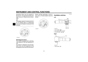
EAU1234B
Handlebar switches Left
Right
ZAUM0916
ZAUM0917
1. Horn switch “ ”
2. Turn signal switch “ / ”
3. Dimmer switch “ / ”
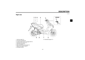
1. Start switch “ ”ZAUM0918
12
3
1
ZAUM0919
U1PHE0E0.book Page 6 Wednesday, August 29, 2012 4:42 PM
Page 23 of 74

INSTRUMENT AND CONTROL FUNCTIONS
3-7
3
EAU12400
Dimmer switch “ / ”
Set this switch to “ ” for the high
beam and to “ ” for the low beam.
EAU12460
Turn signal switch “ / ”
To signal a right-hand turn, push this
switch to “ ”. To signal a left-hand
turn, push this switch to “ ”. When re-
leased, the switch returns to the center
position. To cancel the turn signal
lights, push the switch in after it has re-
turned to the center position.
EAU12500
Horn switch “ ”
Press this switch to sound the horn.
EAUM1132
Start switch “ ”
Push this switch while applying the
front or rear brake to crank the engine
with the starter. See page 5-1 for start-
ing instructions prior to starting the en-
gine.
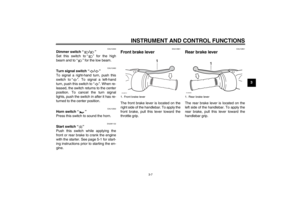
EAU12901
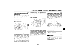
Front brake lever The front brake lever is located on the
right side of the handlebar. To apply the
front brake, pull this lever toward the
throttle grip.
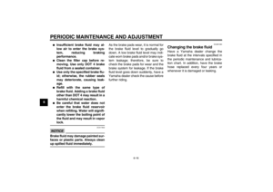
EAU12951
Rear brake lever The rear brake lever is located on the
left side of the handlebar. To apply the
rear brake, pull this lever toward the
handlebar grip.
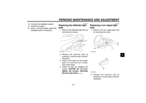
1. Front brake lever
1
ZAUM0791
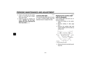
1. Rear brake lever
1
ZAUM0085
U1PHE0E0.book Page 7 Wednesday, August 29, 2012 4:42 PM
Page 24 of 74
INSTRUMENT AND CONTROL FUNCTIONS
3-8
3
EAUM2900
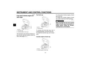
Fuel and 2-stroke engine oil
tank caps The fuel tank cap and the 2-stroke en-
gine oil tank cap are located under the
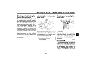
seat. (See page 3-11.)Fuel tank cap
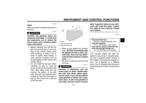
To remove the fuel tank cap, turn it
counterclockwise, and then pull it off.
To install the fuel tank cap, turn it clock-
wise.
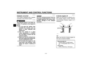
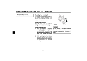
2-stroke engine oil tank capTo remove the 2-stroke engine oil tank
cap, pull it off.
To install the 2-stroke engine oil tank
cap, push it into the oil tank opening.
WARNING
EWA10141
Make sure that the fuel and 2-stroke
engine oil tank caps are properly in-
stalled before riding the scooter.
Leaking fuel is a fire hazard.
1. Fuel tank cap
2. 2-stroke engine oil tank capZAUM0920
1
2
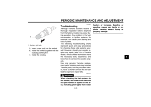
1. Fuel tank cap
1. 2-stroke engine oil tank capZAUM0921
1
ZAUM0922
1
U1PHE0E0.book Page 8 Wednesday, August 29, 2012 4:42 PM


Fuel tank c")