2013 YAMAHA AEROX50 battery
[x] Cancel search: batteryPage 6 of 74

TABLE OF CONTENTSSAFETY INFORMATION ..................1-1
Further safe-riding points ................1-5
DESCRIPTION ..................................2-1
Left view ..........................................2-1
Right view ........................................2-2
Controls and instruments.................2-3
INSTRUMENT AND CONTROL
FUNCTIONS.......................................3-1
Main switch/steering lock ................3-1
Indicator lights and warning light ....3-2
Speedometer unit (NS50N) .............3-3
Multi-function display (NS50)...........3-4
Handlebar switches ........................3-6
Front brake lever ............................3-7
Rear brake lever .............................3-7
Fuel and 2-stroke engine oil tank
caps .............................................3-8
Fuel .................................................3-9
Catalytic converter ........................3-10
2-stroke engine oil ........................3-10
Kickstarter .....................................3-11
Seats ............................................3-11
Storage compartment ...................3-12
Adjusting the shock absorber
assembly (if equipped) ...............3-13FOR YOUR SAFETY –
PRE-OPERATION CHECKS............. 4-1
OPERATION AND IMPORTANT
RIDING POINTS................................. 5-1
Starting a cold engine .................... 5-1
Starting off ...................................... 5-2
Acceleration and deceleration ........ 5-2
Braking ........................................... 5-2
Tips for reducing fuel
consumption ............................... 5-3
Engine break-in .............................. 5-3
Parking ........................................... 5-4
PERIODIC MAINTENANCE AND
ADJUSTMENT................................... 6-1
Periodic maintenance chart for
the emission control system ....... 6-2
General maintenance and
lubrication chart .......................... 6-3
Removing and installing the cowling
and panel .................................... 6-6
Checking the spark plug ................. 6-7
Final transmission oil ...................... 6-8
Coolant ........................................... 6-9
Cleaning the air filter element ...... 6-10
Adjusting the carburetor ............... 6-11
Checking the throttle grip free
play ........................................... 6-11
Tires ............................................. 6-12
Cast wheels .................................. 6-14Checking the front and rear brake
lever free play ........................... 6-14
Checking the front and rear brake
pads .......................................... 6-15
Checking the brake fluid level ...... 6-15
Changing the brake fluid .............. 6-16
Checking and lubricating
the throttle grip and cable ......... 6-17
Lubricating the front and rear
brake levers .............................. 6-17
Checking and lubricating the
centerstand ............................... 6-17
Checking the front fork ................. 6-18
Checking the steering .................. 6-19
Checking the wheel bearings ....... 6-19
Battery ......................................... 6-19
Replacing the fuse ....................... 6-21
Replacing the headlight bulb ....... 6-22
Replacing the tail/brake light
bulb ........................................... 6-23
Replacing a turn signal light
bulb ........................................... 6-23
License plate light ........................ 6-24
Replacing the auxiliary light bulb
(if equipped) .............................. 6-24
Troubleshooting ........................... 6-25
Troubleshooting charts ................ 6-26
SCOOTER CARE AND STORAGE... 7-1
Matte color caution ........................ 7-1
Care ............................................... 7-1U1PHE0E0.book Page 1 Wednesday, August 29, 2012 4:42 PM
Page 15 of 74

DESCRIPTION
2-2
2
EAU10420
Right view
NS50N
123 4
5
6 7 8 9
1. Grab bar (page 5-2)
2. Fuel tank cap (page 3-8)
3. 2-stroke engine oil tank cap (page 3-8/3-10)
4. Passenger seat (page 3-11)
5. Rider seat (page 3-11)
6. Main switch/steering lock (page 3-1)
7. Battery/fuse (page 6-19/6-21)
8. Passenger footrest9. Centerstand (page 6-17)
U1PHE0E0.book Page 2 Wednesday, August 29, 2012 4:42 PM
Page 32 of 74

FOR YOUR SAFETY – PRE-OPERATION CHECKS
4-2
4
Rear brake Check operation.
If soft or spongy, have Yamaha dealer bleed hydraulic system.
Check brake pads for wear.
Replace if necessary.
Check fluid level in reservoir.
If necessary, add specified brake fluid to specified level.
Check hydraulic system for leakage.6-14, 6-15, 6-15
Throttle grip Make sure that operation is smooth.
Check throttle grip free play.
If necessary, have Yamaha dealer adjust throttle grip free play and lubricate cable
and grip housing.6-11, 6-17
Wheels and tires Check for damage.
Check tire condition and tread depth.
Check air pressure.
Correct if necessary.6-12, 6-14
Brake levers Make sure that operation is smooth.
Lubricate lever pivoting points if necessary.6-17
Centerstand Make sure that operation is smooth.
Lubricate pivot if necessary.6-17
Chassis fasteners Make sure that all nuts, bolts and screws are properly tightened.
Tighten if necessary.—
Instruments, lights, signals
and switches Check operation.
Correct if necessary.—
Battery Check fluid level.
Fill with distilled water if necessary.6-19 ITEM CHECKS PAGE
U1PHE0E0.book Page 2 Wednesday, August 29, 2012 4:42 PM
Page 33 of 74

OPERATION AND IMPORTANT RIDING POINTS
5-1
5
EAU15951
Read the Owner’s Manual carefully to
become familiar with all controls. If
there is a control or function you do not
understand, ask your Yamaha dealer.
WARNING
EWA10271
Failure to familiarize yourself with
the controls can lead to loss of con-
trol, which could cause an accident
or injury.
EAUM2760
Starting a cold engine NOTICE
ECA10250
See page 5-3 for engine break-in in-
structions prior to operating the ve-
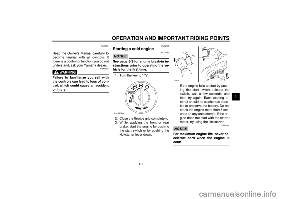
hicle for the first time.1. Turn the key to “ ”.
2. Close the throttle grip completely.
3. While applying the front or rear
brake, start the engine by pushing
the start switch or by pushing the
kickstarter lever down.If the engine fails to start by push-
ing the start switch, release the
switch, wait a few seconds, and
then try again. Each starting at-
tempt should be as short as possi-
ble to preserve the battery. Do not
crank the engine more than 5 sec-
onds on any one attempt. If the en-
gine does not start with the starter
motor, try using the kickstarter.
NOTICE
ECA11042
For maximum engine life, never ac-
celerate hard when the engine is
cold!
ZAUM0944
ZAUM0367
U1PHE0E0.book Page 1 Wednesday, August 29, 2012 4:42 PM
Page 39 of 74

PERIODIC MAINTENANCE AND ADJUSTMENT
6-3
6
EAU17718
General maintenance and lubrication chart NO. ITEM CHECK OR MAINTENANCE JOBODOMETER READING
ANNUAL
CHECK 1000 km
(600 mi)6000 km
(3500 mi)12000 km
(7000 mi)18000 km
(10500 mi)24000 km
(14000 mi)
1 Air filter element Clean.√√
Replace.√√
2*Battery Check electrolyte level and specif-
ic gravity.
Make sure that the breather hose
is properly routed.√√√√√
3*Front brake Check operation, fluid level and
vehicle for fluid leakage.√√√√√√
Replace brake pads. Whenever worn to the limit
4*Rear brake Check operation, fluid level and
vehicle for fluid leakage.√√√√√√
Replace brake pads. Whenever worn to the limit
5*Brake hose Check for cracks or damage.
Check for correct routing and
clamping.√√√√√
Replace. Every 4 years
6*Brake fluid Replace. Every 2 years
7*Wheels Check runout and for damage.√√√√
8*Tires Check tread depth and for dam-
age.
Replace if necessary.
Check air pressure.
Correct if necessary.√√√√√
U1PHE0E0.book Page 3 Wednesday, August 29, 2012 4:42 PM
Page 55 of 74

PERIODIC MAINTENANCE AND ADJUSTMENT
6-19
6
EAU45511
Checking the steering Worn or loose steering bearings may
cause danger. Therefore, the operation
of the steering must be checked as fol-
lows at the intervals specified in the pe-
riodic maintenance and lubrication
chart.
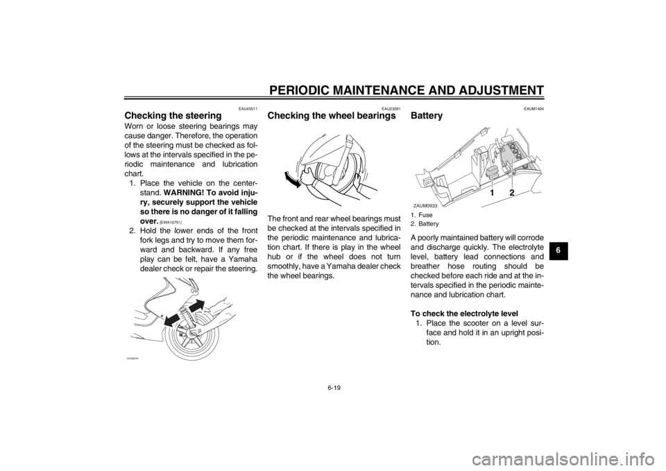
1. Place the vehicle on the center-
stand. WARNING! To avoid inju-
ry, securely support the vehicle
so there is no danger of it falling
over.
[EWA10751]
2. Hold the lower ends of the front
fork legs and try to move them for-
ward and backward. If any free
play can be felt, have a Yamaha
dealer check or repair the steering.
EAU23291
Checking the wheel bearings The front and rear wheel bearings must
be checked at the intervals specified in
the periodic maintenance and lubrica-
tion chart. If there is play in the wheel
hub or if the wheel does not turn
smoothly, have a Yamaha dealer check
the wheel bearings.
EAUM1404
Battery A poorly maintained battery will corrode
and discharge quickly. The electrolyte
level, battery lead connections and
breather hose routing should be
checked before each ride and at the in-
tervals specified in the periodic mainte-
nance and lubrication chart.
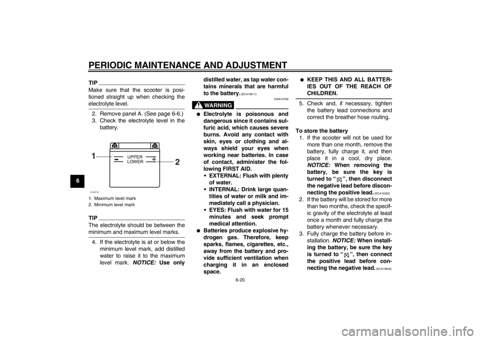
To check the electrolyte level
1. Place the scooter on a level sur-
face and hold it in an upright posi-
tion.
ZAUM0297
1. Fuse
2. BatteryZAUM0933
12
U1PHE0E0.book Page 19 Wednesday, August 29, 2012 4:42 PM
Page 56 of 74

PERIODIC MAINTENANCE AND ADJUSTMENT
6-20
6
TIPMake sure that the scooter is posi-
tioned straight up when checking the
electrolyte level.2. Remove panel A. (See page 6-6.)
3. Check the electrolyte level in the
battery.TIPThe electrolyte should be between the
minimum and maximum level marks.4. If the electrolyte is at or below the
minimum level mark, add distilled
water to raise it to the maximum
level mark. NOTICE: Use onlydistilled water, as tap water con-
tains minerals that are harmful
to the battery.
[ECA10611]
WARNING
EWA10760
●
Electrolyte is poisonous and
dangerous since it contains sul-
furic acid, which causes severe
burns. Avoid any contact with
skin, eyes or clothing and al-
ways shield your eyes when
working near batteries. In case
of contact, administer the fol-
lowing FIRST AID.
EXTERNAL: Flush with plenty
of water.
INTERNAL: Drink large quan-
tities of water or milk and im-
mediately call a physician.
EYES: Flush with water for 15
minutes and seek prompt
medical attention.
●
Batteries produce explosive hy-
drogen gas. Therefore, keep
sparks, flames, cigarettes, etc.,
away from the battery and pro-
vide sufficient ventilation when
charging it in an enclosed
space.
●
KEEP THIS AND ALL BATTER-
IES OUT OF THE REACH OF
CHILDREN.
5. Check and, if necessary, tighten
the battery lead connections and
correct the breather hose routing.
To store the battery
1. If the scooter will not be used for
more than one month, remove the
battery, fully charge it, and then
place it in a cool, dry place.
NOTICE: When removing the
battery, be sure the key is
turned to “ ”, then disconnect
the negative lead before discon-
necting the positive lead.
[ECA16302]
2. If the battery will be stored for more
than two months, check the specif-
ic gravity of the electrolyte at least
once a month and fully charge the
battery whenever necessary.
3. Fully charge the battery before in-
stallation. NOTICE: When install-
ing the battery, be sure the key
is turned to “ ”, then connect
the positive lead before con-
necting the negative lead.
[ECA16840]
1. Maximum level mark
2. Minimum level mark1
2
+
UPPER
LOWER
ZAUM0106
U1PHE0E0.book Page 20 Wednesday, August 29, 2012 4:42 PM
Page 57 of 74

PERIODIC MAINTENANCE AND ADJUSTMENT
6-21
6 4. After installation, make sure that
the battery leads are properly con-
nected to the battery terminals and
that the breather hose is properly
routed, in good condition, and not
obstructed. NOTICE: If the
breather hose is positioned in
such a way that the frame is ex-
posed to electrolyte or gas ex-
pelled from the battery, the
frame could suffer structural
and external damages.
[ECA10601]EAU23503
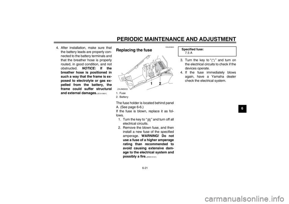
Replacing the fuse The fuse holder is located behind panel
A. (See page 6-6.)
If the fuse is blown, replace it as fol-
lows.
1. Turn the key to “ ” and turn off all
electrical circuits.
2. Remove the blown fuse, and then
install a new fuse of the specified
amperage. WARNING! Do not
use a fuse of a higher amperage
rating than recommended to
avoid causing extensive dam-
age to the electrical system and
possibly a fire.
[EWA15131]
3. Turn the key to “ ” and turn on
the electrical circuits to check if the
devices operate.
4. If the fuse immediately blows
again, have a Yamaha dealer
check the electrical system.
1. Fuse
2. BatteryZAUM0933
12
Specified fuse:
7.5 A
U1PHE0E0.book Page 21 Wednesday, August 29, 2012 4:42 PM