2013 VOLVO V60 ABS
[x] Cancel search: ABSPage 168 of 422

04 Driver support
Distance Warning*
04
166* Option/accessory, for more information, see Introduction.
Different time intervals to the
vehicle in front can be
selected and shown in the
display as 1-5 horizontal lines
- the more lines the longer the
time interval. One line corre-
sponds to
approximately 1 second to the vehicle in front,
5 lines approximately 3 seconds.
The number of lines for the
selected time interval is
shown during the setting itself
and for several seconds after-
wards. Then a smaller scale
version of the symbol is
shown to the right of the dis-
play. The same symbol is also shown when
adaptive cruise control is activated.
NOTE
The higher the speed, the longer the calcu-
lated distance in metres for a specific time
interval.
The set time interval is also used by the
adaptive cruise control function, see
page 156.
Only use the time interval that is allowed in
accordance with local traffic regulations.
Limitations
The function uses the same radar sensor as
adaptive cruise control and the collision warn-
ing system. For more information on the radar
sensor and its limitations, see page 160.
NOTE
Strong sunlight, reflections or strong varia-
tions in light intensity, as well as wearing
sunglasses, could mean that the warning
light in the windscreen cannot be seen.
Poor weather or winding roads could affect
the radar sensor's capacity to detect vehi-
cles in front.
The size of other vehicles could also affect
detection capacity, e.g. motorcycles. This
could mean that the warning lamp illumi-
nates at a shorter distance than the setting
or that the warning is temporarily absent.
Extremely high speeds can also cause the
lamp to illuminate at a shorter distance than
that set due to limitations in sensor range.
ProCarManuals.com
Page 171 of 422

04 Driver support
City Safety™
04
169
If the difference in speed between the vehicles
is greater than 15 km/h then City Safety™ may
not prevent the collision on its own. To obtain
full brake force, the driver must depress the
brake pedal. This could then make it possible
to prevent a collision, even at speed differen-
ces above 15 km/h.
When the function is activated and brakes, the
instrument panel display shows a message to
the effect that the function is/has been active.
NOTE
The brake lights come on when City
Safety™ brakes the car.
Operation
NOTE
The City Safety™ function is always ena-
bled after the engine has been started via
key position I and II (see page 78 on key
positions).
On and OffIn certain situations, it may advisable to disable
City Safety™, e.g. where leafy branches could
sweep over the bonnet and/or windscreen.
After starting the engine City Safety™ can be
deactivated as follows:
•Using MY CAR on the centre console dis-
play screen with its menu system, search
and locate Settings
Car settings
Driver support systemsCity Safety.
Select the
Off option. For more information
on the menu system MY CAR, see
page 202.
However, the function will be enabled the
next time the engine is started, regardless
of whether the system was enabled or dis-
abled when the engine was switched off.
WARNING
The laser sensor also transmits laser light
when City Safety™ is disabled manually.
To enable City Safety™ again:
•Follow the same procedure as for disa-
bling, but select the On option.
Limitations
The sensor in City Safety™ is designed to
detect cars and other large vehicles in front of
the car irrespective of whether it is day or night.
However, the sensor has limitations and has
poorer functionality - or none at all - in e.g.
heavy snowfall or rain, dense fog, dust storms
or snow flurries. Mist, dirt, ice or snow on the
windscreen may disrupt the function.Low-hanging objects, e.g. a flag/pennant for
projecting load, or accessories such as auxili-
ary lamps and bull bars that are higher than the
bonnet limit the function.
The laser light from the sensor in City
Safety™ measures how the light is reflected.
The sensor cannot detect objects with low
reflection capacity. The rear sections of the
vehicle generally reflect the light sufficiently
thanks to the number plate and rear light reflec-
tors.
On slippery road surfaces the braking distance
is extended, which may reduce the capacity of
City Safety™ to avoid a collision. In such sit-
uations the ABS and DSTC systems will pro-
vide best possible braking force with main-
tained stability.
When your own car is reversing, City Safety™
is temporarily deactivated.
City Safety™ is not activated at low speeds -
under 4 km/h, which is why the system does
not intervene in situations where a vehicle in
front is being approached very slowly, e.g.
when parking.
Driver commands are always prioritised, which
is why City Safety™ does not intervene in sit-
uations where the driver is steering or acceler-
ating in a clear manner, even if a collision is
unavoidable.
ProCarManuals.com
Page 179 of 422

04 Driver support
Collision Warning with Auto Brake & Pedestrian Protection*
04
* Option/accessory, for more information, see Introduction.177
For the sensors to work correctly, they must be
kept clear of dirt, ice and snow, and be cleaned
regularly with water and car shampoo.
NOTE
Dirt, ice and snow covering the sensors will
reduce their function and may prevent
measurement.
Limitations
Collision Warning with Auto Brake and Pedes-
trian Detection is active from approx. 4 km/h.
The visual warning signal (no. [1] in the illustra-
tion on page 173) may be difficult to notice in
the event of strong sunlight, reflections, when
sunglasses are being worn or if the driver is not
looking straight ahead. The warning sound
should therefore always be activated.
On slippery road surfaces the braking distance
is extended, which may reduce the capacity to
avoid a collision. In such situations the ABS
and DSTC systems will provide best possible
braking force with maintained stability.
NOTE
The visual warning signal can be temporarily
disengaged in the event of high passenger
compartment temperature caused by
strong sunlight for example. If this occurs
then the warning sound is activated even if
it is deactivated in the menu system.
•Warnings may not appear if the dis-
tance to the vehicle in front is small or if
steering wheel and pedal movements
are large, e.g. a very active driving style.
WARNING
Warnings and brake interventions could be
implemented late or not at all if the traffic
situation or external influences mean that
the radar or camera sensor cannot detect a
pedestrian or a vehicle in front correctly.
The sensor system has a limited range for
pedestrians and the system therefore pro-
vides effective warnings and brake inter-
ventions at vehicle speeds up to 50 km/h.
For stationary or slow-moving vehicles,
warnings and brake interventions are effec-
tive at vehicle speeds up to 70 km/h.
Warnings for stationary or slow-moving
vehicles could be disengaged due to dark-
ness or poor visibility.
Warnings and brake interventions for
pedestrians are switched off at vehicle
speeds exceeding 80 km/h.
The collision warning system uses the same
radar sensors as adaptive cruise control. For
more information on the radar sensor and its
limitations, see page 178.
If warnings are perceived as being too frequent
or disturbing then the warning distance can be
reduced. This then leads to the system provid-
ing a warning at a later stage, which reduces
the total number of warnings; see the section
"Set warning distance" on page 176.
ProCarManuals.com
Page 228 of 422

05 Comfort and driving pleasure
Adapting driving characteristics
05
226* Option/accessory, for more information, see Introduction.
Active chassis - Four-C*
Active chassis, Four-C (Continously Controlled
Chassis Concept), regulates the characteris-
tics of the shock absorbers so that the car's
driving characteristics can be adjusted. There
are three settings: Comfort, Sport and
Advanced.
ComfortThis setting means that the car is perceived as
being more comfortable on rough and uneven
road surfaces. Shock absorption is soft and the
movement of the body is smooth and gentle.
SportThis setting means that the car is perceived as
being more sporty and is recommended for
more active driving. Steering response is faster
than in the Comfort mode. Shock absorption is
harder and the body follows the road in order
to reduce rolling during cornering.
AdvancedThis setting is only recommended on very even
and smooth road surfaces.
The shock absorbers are optimised for maxi-
mum roadholding and rolling in bends is further
minimised.
Operation
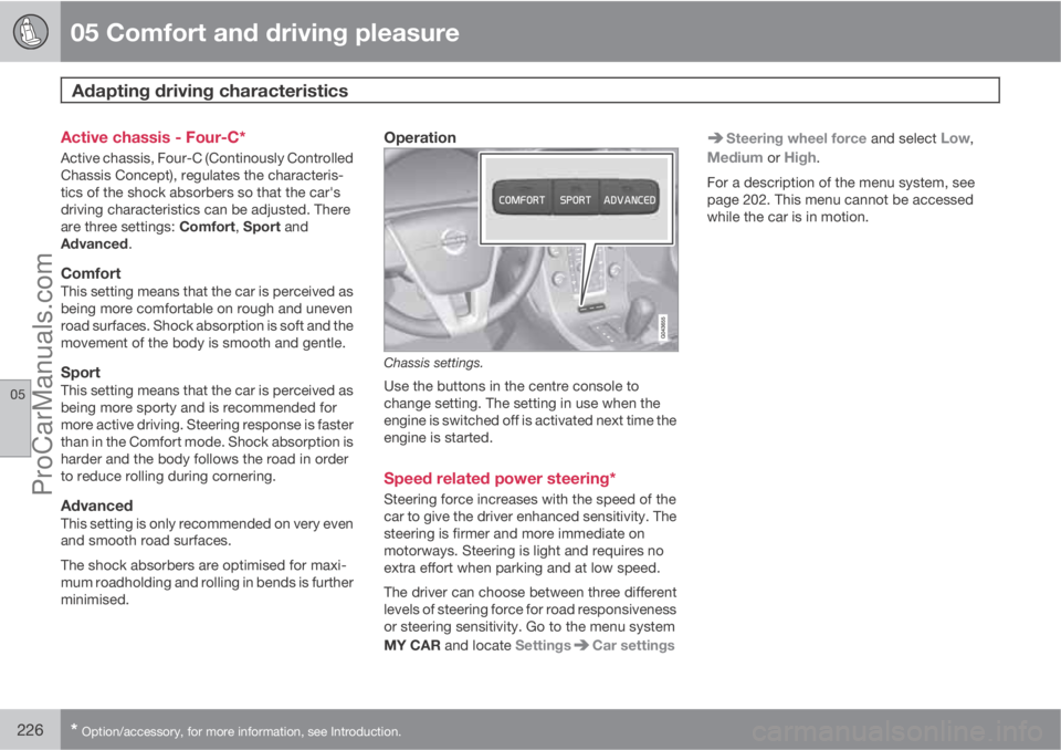
Chassis settings.
Use the buttons in the centre console to
change setting. The setting in use when the
engine is switched off is activated next time the
engine is started.
Speed related power steering*
Steering force increases with the speed of the
car to give the driver enhanced sensitivity. The
steering is firmer and more immediate on
motorways. Steering is light and requires no
extra effort when parking and at low speed.
The driver can choose between three different
levels of steering force for road responsiveness
or steering sensitivity. Go to the menu system
MY CAR and locate Settings
Car settings
Steering wheel force and select Low,
Medium or High.
For a description of the menu system, see
page 202. This menu cannot be accessed
while the car is in motion.
ProCarManuals.com
Page 300 of 422

07 During your journey
Driving with a trailer
07
298* Option/accessory, for more information, see Introduction.
General
Payload depends on the car's kerb weight. The
total of the weight of the passengers and all
accessories, e.g. towbar, reduces the car's
payload by a corresponding weight. For more
detailed information on weights, see
page 373.
If the towing bracket is mounted by Volvo, then
the car is delivered with the necessary equip-
ment for driving with a trailer.
•The car's towing bracket must be of an
approved type.
•If the towbar is retrofitted, check with your
Volvo dealer that the car is fully equipped
for driving with a trailer.
•Distribute the load on the trailer so that the
weight on the towing bracket complies
with the specified maximum towball load.
•Increase the tyre pressure to the recom-
mended pressure for a full load. For tyre
pressure label location, see page 317.
•The engine is loaded more heavily than
usual when driving with a trailer.
•Do not tow a heavy trailer when the car is
brand new. Wait until it has been driven at
least 1000 km.
•The brakes are loaded much more than
usual on long and steep downhill slopes.
Downshift to a lower gear and adjust your
speed.
•For safety reasons, the maximum permit-
ted speed for the car when coupled with a
trailer should not be exceeded. Follow the
regulations in force for the permitted
speeds and weights.
•Maintain a low speed when driving with a
trailer up long, steep ascents.
•Avoid driving with a trailer on inclines of
more than 12%.
Trailer cableAn adapter is required if the car's towing
bracket has 13 pin electrics and the trailer has
7 pin electrics. Use an adapter cable approved
by Volvo. Make sure the cable does not drag
on the ground.
Direction indicators and brake lights on
the trailer
If any of the trailer's lamps for direction indica-
tors are broken, then the combined instrument
panel's symbol for direction indicators flashes
faster than normal and the display shows the
text
Bulb fail - Ind. signal trailer.
If any of the trailer's lamps for the brake light
are broken then the
Bulb fail - Stop lamp
trailer text is shown.
Level control*The rear shock absorbers maintain a constant
height irrespective of the car's load (up to the
maximum permissible weight). When the car isstationary the rear of the car lowers slightly,
which is normal.
Trailer weightsFor information on Volvo's permitted trailer
weights, see page 374.
NOTE
The stated maximum permitted trailer
weights are those permitted by Volvo.
National vehicle regulations can further limit
trailer weights and speeds. Towbars can be
certified for higher towing weights than the
car can actually tow.
WARNING
Follow the stated recommendations for
trailer weights. Otherwise, the car and trailer
may be difficult to control in the event of
sudden movement and braking.
Manual gearbox
OverheatingWhen driving with a trailer in hilly terrain in a hot
climate there may be a risk of overheating.
•Do not run the engine at higher revolutions
than 4500 rpm (diesel engines: 3500 rpm)
- otherwise the oil temperature may
become too high.
ProCarManuals.com
Page 349 of 422

09 Maintenance and service
Battery09
* Option/accessory, for more information, see Introduction.347
NOTE
Tighten the screws to 30 Nm. Check the
torque with a torque wrench.
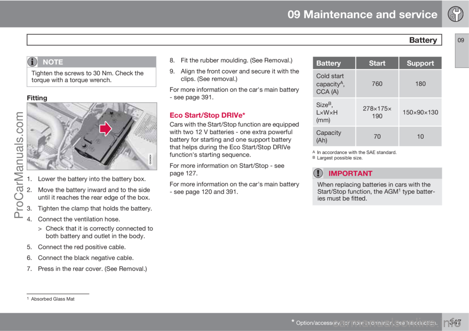
Fitting
1. Lower the battery into the battery box.
2. Move the battery inward and to the side
until it reaches the rear edge of the box.
3. Tighten the clamp that holds the battery.
4. Connect the ventilation hose.
> Check that it is correctly connected to
both battery and outlet in the body.
5. Connect the red positive cable.
6. Connect the black negative cable.
7. Press in the rear cover. (See Removal.)8. Fit the rubber moulding. (See Removal.)
9. Align the front cover and secure it with the
clips. (See removal.)
For more information on the car's main battery
- see page 391.
Eco Start/Stop DRIVe*
Cars with the Start/Stop function are equipped
with two 12 V batteries - one extra powerful
battery for starting and one support battery
that helps during the Eco Start/Stop DRIVe
function's starting sequence.
For more information on Start/Stop - see
page 127.
For more information on the car's main battery
- see page 120 and 391.
BatteryStartSupport
Cold start
capacityA,
CCA (A)760180
SizeB,
L×W×H
(mm)278×175×
190150×90×130
Capacity
(Ah)7010
AIn accordance with the SAE standard.BLargest possible size.
IMPORTANT
When replacing batteries in cars with the
Start/Stop function, the AGM1 type batter-
ies must be fitted.
1Absorbed Glass Mat
ProCarManuals.com
Page 354 of 422

09 Maintenance and service
Fuses 09
352* Option/accessory, for more information, see Introduction.
General fuses, engine compartmentOn the inside of the cover there are tweezers
that facilitate the procedure for the removal
and fitting of fuses.
Positions (see preceding illustration)Engine compartment, upper
Engine compartment, front
Engine compartment, lower
These fuses are all located in the engine com-
partment box. The fuses in (C) are located
under (A).
On the inside of the cover is a label that shows
the location of the fuses.
•Fuses 1-7 and 42-44 are of the "Midi Fuse"
type and must only be replaced by a work-
shop
1.
•Fuses 8-15 and 34 are of the "JCASE" type
and should be replaced by a workshop1.
•Fuses 16-33 and 35-41 are of the "Mini
Fuse" type.
FunctionA
Primary fuse for the central elec-
tronic module (CEM) with fuse
box B under the glovebox
A
50
Primary fuse for the central elec-
tronic module (CEM) with fuse
box B under the glovebox50
Primary fuse for central electri-
cal unit in cargo areaA60
Primary fuse for central electri-
cal unit in passenger compart-
ment with fuse box A under the
glovebox
A
60
Primary fuse for central electri-
cal unit in passenger compart-
ment with fuse box A under the
glovebox
A
60
--
PTC element, air preheater*A100
Headlamp washers*20
Windscreen wipers30
FunctionA
Parking heater*25
Ventilation fanA40
--
ABS pump40
ABS valves20
--
Headlamp levelling*; Active
Xenon headlamps - ABL*10
Primary fuse for the central elec-
tronic module (CEM) with fuse
box B under the glovebox20
ABS5
Speed related power steering*5
Engine control module; Trans-
mission control module; Air-
bags10
Heated washer nozzles*10
1An authorised Volvo workshop is recommended.
ProCarManuals.com
Page 366 of 422

09 Maintenance and service
Car care 09
364
To achieve best results Volvo recommends
cleaning and the application of protective
cream once to four times per year (or more if
necessary). The Volvo Leather Care kit is avail-
able from your Volvo dealer.
IMPORTANT
•Certain items of coloured clothing (for
example, jeans and suede garments)
may stain the upholstery.
•Never use strong solvents. Such prod-
ucts may damage fabric, vinyl and
leather upholstery.
Washing instructions for leather
upholstery
1. Pour the leather cleaner on the dampened
sponge and squeeze out a strong foam.
2. Work the dirt away with gentle circular
movements.
3. Dab accurately with the sponge on the
stains. Allow the sponge to absorb the
stain. Do not rub.
4. Wipe off with soft paper or a cloth and
allow the leather to dry completely.
Protective treatment of leather
upholstery
1. Pour a small amount of the protective
cream on the felted cloth and massage in
a thin layer of cream with gentle circular
movements on the leather.
2. Allow the leather to dry for 20 minutes
before use.
The leather has now been given improved pro-
tection against stains and improved UV pro-
tection.
Washing instructions for the leather
steering wheel
•Remove dirt and dust with a soft pre-mois-
tened sponge and neutral soap.
•Leather needs to breathe. Never cover the
leather steering wheel with protective plas-
tic.
•Use natural oils. Volvo's leather care
agents are recommended for best results.
If the steering wheel has stains:
Group 1 (ink, wine, coffee, milk, sweat and
blood)
–Use a soft cloth or sponge. Mix a 5%
ammonia solution. (For blood stains, use a
solution of 2 dl water and 25g salt.)Group 2 (fats, oils, sauces and chocolate)
1. Same procedure as group 1.
2. Polish with an absorbent paper or cloth.
Group 3 (dry dirt, dust)
1. Use a soft brush to remove the dirt.
2. Same procedure as group 1.
Treating stains on interior plastic, metal
and wood parts
A fibrillated fibre or microfibre cloth, lightly
moistened with water, available from Volvo
dealers, is recommended for cleaning interior
parts and surfaces.
Do not scrape or rub stains. Never use strong
stain removers. A special cleaning agent avail-
able from Volvo dealers can be used for more
difficult cleaning.
Cleaning seatbeltsUse water and a synthetic detergent. A special
textile cleaning agent is available from your
Volvo dealer. Make sure the seatbelt is dry
before allowing it to retract.
ProCarManuals.com