Page 346 of 422

09 Maintenance and service
Battery 09
344
Operation
The service life and function of the battery is
influenced by factors such as the number of
starts, discharging, driving style, driving con-
ditions, climatic conditions etc.
•Never disconnect the battery when the
engine is running.
•Check that the cables to the battery are
correctly connected and properly tight-
ened.
WARNING
•The battery can generate oxyhydrogen
gas, which is highly explosive. A spark
can be formed if a jump lead is con-
nected incorrectly, and this can be
enough for the battery to explode.
•The battery contains sulphuric acid,
which can cause serious burns.
•If sulphuric acid comes into contact
with eyes, skin or clothing, flush with
large quantities of water. If acid
splashes into the eyes - seek medical
attention immediately.
NOTE
The life of the battery is shortened if it
becomes discharged repeatedly.
The life of the battery is affected by several
factors, including driving conditions and cli-
mate. Battery starting capacity decreases
gradually with time and therefore needs to
be recharged if the car is not used for a
longer time or when it is only driven short
distances. Extreme cold further limits star-
ting capacity.
To maintain the battery in good condition, at
least 15 minutes of driving/week is recom-
mended or that the battery is connected to
a battery charger with automatic trickle
charging.
A battery that is kept fully charged has a
maximum service life.
IMPORTANT
Never use a quick charger to charge the
battery.
IMPORTANT
If the following instruction is not observed
then the energy saving function for infotain-
ment may be temporarily disengaged, and/
or the message in the information display
about the main battery's state of charge
may be temporarily inapplicable, following
the connection of an external battery or bat-
tery charger:
•The negative battery terminal on the
car's main battery must never be used
for connecting an external battery or
battery charger - only the car chassis
may be used as the grounding point.
See the section "Start assistance" - for a
description of how the cable clamps must
be attached.
ProCarManuals.com
Page 350 of 422
 the more
the batteries must be charged =
increased fuel consumption.
•When")
09 Maintenance and service
Battery 09
348
NOTE
•The higher the current take-off in the car
(extra cooling/heating, etc.) the more
the batteries must be charged =
increased fuel consumption.
•When the capacity of the battery has
fallen below the lowest permissible level
then the Start/Stop function is disen-
gaged.
Temporarily reduced Start/Stop function due
to high current take-off means:
•The engine starts automatically2 without
the driver depressing the clutch pedal
(manual gearbox).
•The engine starts automatically without the
driver lifting his/her foot off the foot brake
pedal (automatic gearbox).
Location of the batteries
A: Left-hand drive car. B: Right-hand drive car. 1.
Battery for starting3 2. Support battery.
The support battery normally requires no more
service than the normal battery that is used for
starting. A workshop should be contacted in
the event of questions or problems - an author-
ised Volvo workshop is recommended.
IMPORTANT
If the following instruction is not observed
then the Start/Stop function may temporar-
ily cease to work after the connection of an
external battery or battery charger:
•The negative battery terminal on the
car's main battery must never be used
for connecting an external battery or
battery charger - only the car chassis
may be used as the grounding point.
See the section "Start assistance" - for a
description of how the cable clamps must
be attached.
2Automatic starting can only take place if the gear lever is in neutral position.3The battery for starting is described in detail on page 345.
ProCarManuals.com
Page 351 of 422

09 Maintenance and service
Battery09
349
NOTE
If the battery has become so discharged
that everything is "black" and in principle
the car does not have all the normal electri-
cal functions and the engine is subsequently
started using an external battery or battery
charger, then the Start/Stop function will be
activated. It will then be possible for the
engine to be auto-stopped but in the event
of an auto-stop the Start/Stop function may
fail to auto-start the engine due to inade-
quate capacity in the battery.
The battery must first be charged in order to
ensure a successful auto-start after an auto-
stop. At an outside temperature of +15 °C
the battery needs to be charged for at least
1 hour. At a lower outside temperature a
charging time of 3-4 hours is recom-
mended. The recommendation is that the
battery is charged using an external battery
charger.
If this is not possible then the recommen-
dation is to temporarily deactivate the
Start/Stop function until the battery has
been adequately recharged.
For more information about recharging the
battery, see the section "Battery" in the
chapter "Maintenance and service".
ProCarManuals.com
Page 352 of 422

09 Maintenance and service
Fuses 09
350
General
All electrical functions and components are
protected by a number of fuses in order to pro-
tect the car's electrical system from damage by
short circuiting or overloading.
If an electrical component or function does not
work, it may be because the component's fuse
was temporarily overloaded and failed. If the
same fuse fails repeatedly then there is a fault
in the circuit. Volvo recommends that you visit
an authorised Volvo workshop for checking.
Changing1. Look in the fuse diagram to locate the fuse.
2. Pull out the fuse and check from the side
to see whether the curved wire has blown.
3. If this is the case, replace it with a new fuse
of the same colour and amperage.
WARNING
Never use a foreign object, or a fuse with an
amperage higher than that specified when
replacing a fuse. This could cause signifi-
cant damage to the electrical system and
possibly lead to fire.
Location, fuse boxes
Central electrical unit locations in a left-hand
drive car. In a right-hand drive car the central
electrical units under the glovebox change
sides.
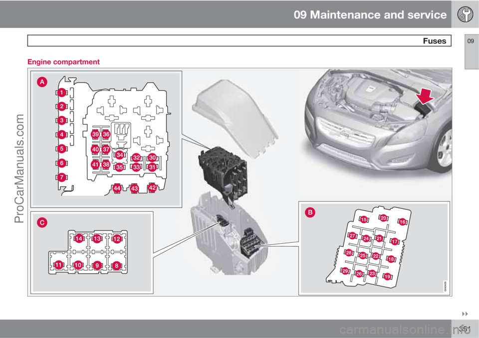
Engine compartment
Under the glovebox
Under the glovebox
Cargo area under the cargo floor
Engine compartment cold zone (only Start/
Stop*)
ProCarManuals.com
Page 353 of 422
09 Maintenance and service
Fuses09
��
351 Engine compartmentProCarManuals.com
Page 354 of 422

09 Maintenance and service
Fuses 09
352* Option/accessory, for more information, see Introduction.
General fuses, engine compartmentOn the inside of the cover there are tweezers
that facilitate the procedure for the removal
and fitting of fuses.
Positions (see preceding illustration)Engine compartment, upper
Engine compartment, front
Engine compartment, lower
These fuses are all located in the engine com-
partment box. The fuses in (C) are located
under (A).
On the inside of the cover is a label that shows
the location of the fuses.
•Fuses 1-7 and 42-44 are of the "Midi Fuse"
type and must only be replaced by a work-
shop
1.
•Fuses 8-15 and 34 are of the "JCASE" type
and should be replaced by a workshop1.
•Fuses 16-33 and 35-41 are of the "Mini
Fuse" type.
FunctionA
Primary fuse for the central elec-
tronic module (CEM) with fuse
box B under the glovebox
A
50
Primary fuse for the central elec-
tronic module (CEM) with fuse
box B under the glovebox50
Primary fuse for central electri-
cal unit in cargo areaA60
Primary fuse for central electri-
cal unit in passenger compart-
ment with fuse box A under the
glovebox
A
60
Primary fuse for central electri-
cal unit in passenger compart-
ment with fuse box A under the
glovebox
A
60
--
PTC element, air preheater*A100
Headlamp washers*20
Windscreen wipers30
FunctionA
Parking heater*25
Ventilation fanA40
--
ABS pump40
ABS valves20
--
Headlamp levelling*; Active
Xenon headlamps - ABL*10
Primary fuse for the central elec-
tronic module (CEM) with fuse
box B under the glovebox20
ABS5
Speed related power steering*5
Engine control module; Trans-
mission control module; Air-
bags10
Heated washer nozzles*10
1An authorised Volvo workshop is recommended.
ProCarManuals.com
Page 355 of 422

09 Maintenance and service
Fuses09
��
* Option/accessory, for more information, see Introduction.353
FunctionA
--
Headlamp control5
--
--
--
Internal relay coils5
Auxiliary lamps*20
Horn15
Relay coil in main relay for
engine management system;
Engine control module (5, 6-cyl.
petrol)10
Transmission control module15
Solenoid clutch A/C (not 5-cyl.
diesel); Coolant pump (5-cyl.
diesel Start/Stop)15
FunctionA
Relay coil in relay for solenoid
clutch A/C (not 5-cyl. diesel);
Relay coil in relay for coolant
pump (5-cyl. diesel Start/Stop);
Relay coils in central electrical
unit in engine compartment cold
zone (Start/Stop)5
Start relayA30
Ignition coils (4-cyl. petrol);
Glow control module (5-cyl. die-
sel)10
Ignition coils (5, 6-cyl. petrol);
Capacitor (6-cyl.)20
Engine control module (petrol)10
Engine control module (diesel)15
FunctionA
Valves (1.6 l petrol); Mass air
flow sensor (1.6 l petrol)
Mass air flow sensor (D4162T);
Control valve, fuel flow
(D4162T)10
Mass air flow sensor (5-cyl. die-
sel, 6-cyl.); Control valves (5-
cyl. diesel); Injectors (5, 6-cyl.
petrol); Engine control module
(5-cyl. petrol, 6-cyl.)15
Solenoid clutch A/C (5, 6-cyl.);
Valves, Engine control module
(6-cyl.) Solenoids (6-cyl. without
turbo); Actuator motors, intake
manifold (6-cyl. without turbo);
Mass air flow sensor (4-cyl. 2.0
l petrol, 5-cyl. petrol); Oil level
sensor (5-cyl. diesel)
Coolant pump (D4162T)10
Lambda-sonds (4-cyl. petrol);
Lambda-sond (diesel); Control
module, radiator roller cover
(manual 5-cyl. 2.0 l diesel)10
EVAP valve (5, 6-cyl. petrol);
Lambda-sonds (5, 6-cyl. petrol)15
ProCarManuals.com
Page 361 of 422
09 Maintenance and service
Fuses09
��
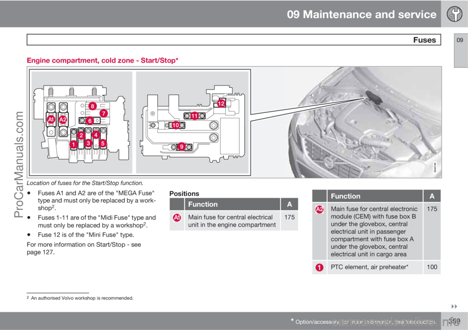
* Option/accessory, for more information, see Introduction.359 Engine compartment, cold zone - Start/Stop*
Location of fuses for the Start/Stop function.
•Fuses A1 and A2 are of the "MEGA Fuse"
type and must only be replaced by a work-
shop
2.
•Fuses 1-11 are of the "Midi Fuse" type and
must only be replaced by a workshop2.
•Fuse 12 is of the "Mini Fuse" type.
For more information on Start/Stop - see
page 127.
Positions
FunctionA
Main fuse for central electrical
unit in the engine compartment175
FunctionA
Main fuse for central electronic
module (CEM) with fuse box B
under the glovebox, central
electrical unit in passenger
compartment with fuse box A
under the glovebox, central
electrical unit in cargo area175
PTC element, air preheater*100
2An authorised Volvo workshop is recommended.
ProCarManuals.com