Page 49 of 296

01 Safety
Booster cushions01
47 Securing a booster cushion
G026517
Position the child correctly on the booster cushion
and fasten the seat belt
WARNING
A child seat should never be used in the
front passenger seat of any vehicle with a
front passenger airbag – not even if the
Passenger airbag off symbol near the rear-
view mirror is illuminated (on vehicles equip-
ped with Occupant Weight Sensor). If the
severity of an accident were to cause the
airbag to inflate, this could lead to serious
injury or death to a child seated in this posi-
tion.
Booster cushions are recommended for chil-
dren who have outgrown convertible seats.
1. Place the booster cushion in the rear seat
of the vehicle.
2. With the child properly seated on the
booster cushion, attach the seat belt to or
around the cushion according to the man-
ufacturer's instructions.
3. Fasten the seat belt by inserting the latch
plate into the buckle (lock) until a distinct
click is audible.
4. Ensure that the seat belt is pulled taut and
fits snugly around the child.
WARNING
•The hip section of the three-point seat
belt must fit snugly across the child's
hips, not across the stomach.
•The shoulder section of the three-point
seat belt should be positioned across
the chest and shoulder.
•The shoulder belt must never be placed
behind the child's back or under the
arm.
Page 50 of 296

01 Safety
ISOFIX/LATCH lower anchors 01
48
Using the ISOFIX/LATCH lower child
seat anchors
G020798
Lower anchors for ISOFIX/LATCH-equipped
child seats are located in both rear seating
positions, hidden below the backrest cushions.
Symbols on the seat back upholstery mark the
anchor positions (see the illustration).
WARNING
The center of the rear seat is not a seating
position. This area is not equipped with a
seat belt or ISOFIX/LATCH anchors. No one
should attempt to sit in this position and
child seats should never be placed in the
center of the rear seat.
To access the anchors:1. Put the child restraint in position.
2. Kneel on the child restraint to press down
the seat cushion and locate the anchors by
feel.
3. Fasten the attachment on the child
restraint's lower straps to the ISOFIX/
LATCH lower anchors.
4. Firmly tension the lower child seat straps
according to the manufacturer's instruc-
tions.
NOTE
•Always follow your child seat manufac-
turer's installation instructions and use
ISOFIX/LATCH lower anchors when-
ever possible.
WARNING
Volvo's ISOFIX/LATCH anchors conform to
FMVSS/CMVSS standards. Always refer to
the child restraint system's manual for
weight and size ratings.
G031682
Fasten the attachment correctly to the ISOFIX/
LATCH lower anchors
WARNING
Be sure to fasten the attachment correctly
to the anchor (see the illustration). If the
attachment is not correctly fastened, the
child restraint may not be properly secured
in the event of a collision.
Page 51 of 296
Page 52 of 296

50* Option/accessory, for more information, see Introduction.
Instrument overview................................................................................ 52
Instrument panel..................................................................................... 54
Indicator and warning symbols............................................................... 56
Symbols – instrument panel.................................................................... 58
Information display.................................................................................. 61
12-volt sockets....................................................................................... 63
Lighting panel.......................................................................................... 64
Left-side steering wheel lever................................................................. 68
Trip computer.......................................................................................... 70
Cruise control*........................................................................................ 72
Right-side steering wheel lever............................................................... 74
Steering wheel adjustment, Hazard warning flashers............................. 76
Power windows....................................................................................... 77
Mirrors..................................................................................................... 78
Personal settings.................................................................................... 81
HomeLink
® Wireless Control System*.................................................... 83
Page 53 of 296
Page 54 of 296
02 Instruments and controls
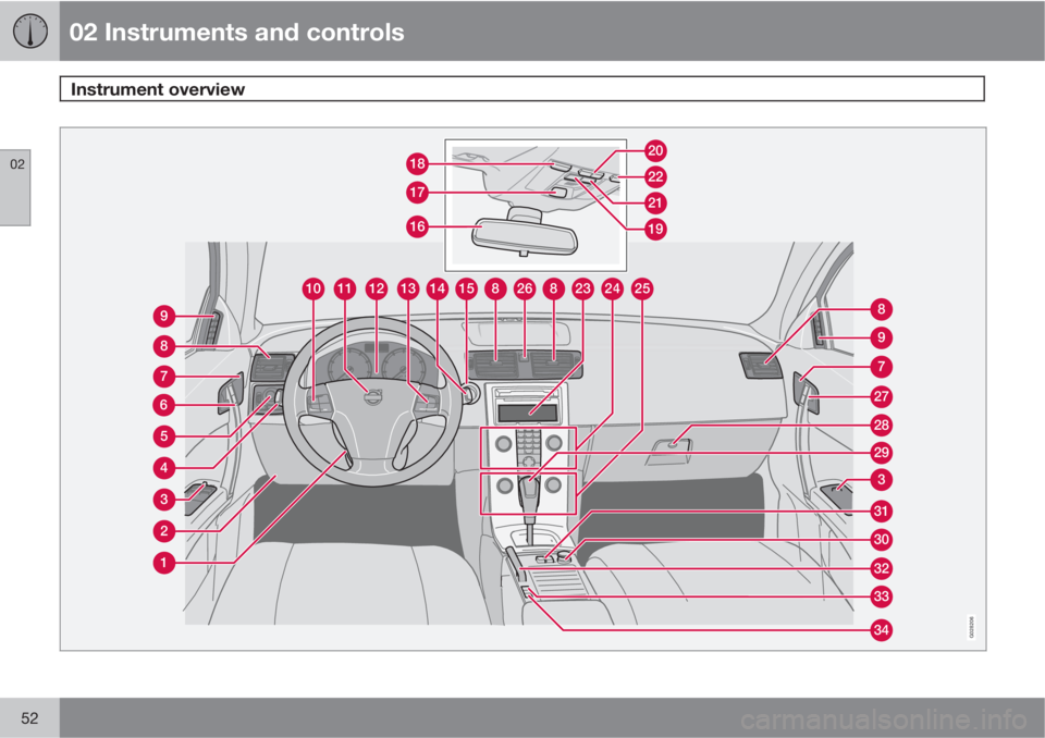
Instrument overview
02
52
2681512101113148232425
27
30
31
29
3
28
8
7
32
34
33
9
7
6
8
9
16
17
1822
20
21
19
3
2
1
5
4
G028206
Page 55 of 296

02 Instruments and controls
Instrument overview
02
* Option/accessory, for more information, see Introduction.53
Steering wheel adjustment
Hood opener
Controls in front doors
Left steering wheel lever
Lighting panel, fuel filler door opener
Door open handle and locking button
Lock indicator light
Climate system air vent
Side window air vent
Cruise control
Horn, airbag
Main instrument panel
Audio controls
Right steering wheel lever
Ignition switch
Rear-view mirror
Seat belt reminder and Occupant
Weight Sensor indicator
Driver's side reading light
Movement detector*, alarm sensor
Courtesy lighting switch
Position for accessory switch
Passenger's side reading light
Display for climate control, personal
settings, and audio system
Controls for personal settings and
audio system
Controls for climate system
Hazard warning flashers
Door open handle and locking button
Glove compartment
Gear selector
12-volt socket
Switch for raising/lowering the power
retractable hard top
Parking brake
Position for optional equipment
Control panel in driver's door
Power windows
Door mirror button, driver's side
Door mirror adjustment control
Door mirror button, passenger's side
Page 56 of 296

02 Instruments and controls
Instrument panel
02
54
Instrument panel
Speedometer
Turn signal, left
Warning symbol – See the following pages
for additional information.
Information display – The display presents
information and warning messages, the
ambient temperature, clock, etc. When the
ambient temperature is between 23 °F and
36 °F (–5 °C and +2 °C), a snowflake sym-
bol is shown in the display. This symbol
serves as a warning for possible slippery
road surfaces. Please note that this symbol
does not indicate a fault with your car. At
low speeds, or when the car is not moving,the temperature readings may be slightly
higher than the actual ambient tempera-
ture.
Information symbol – See the following
pages for additional information.
Turn signal, right
Tachometer – Shows engine speed in
thousands of revolutions per minute (rpm).
Do not drive continuously with the needle
in the red area of the dial, which indicates
maximum allowable engine rpm range.
Instead, shift to a higher gear or slow the
vehicle down. The engine management
system will automatically prevent exces-sively high engines speeds. This will be
noticeable as a pronounced unevenness in
engine speed.
Indicator and information symbols
Fuel gauge, see page 275 for fuel tank vol-
ume. When a warning light in the gauge
comes on, the vehicle should be refueled
as soon as possible, see page 70 for
more information on fuel level and con-
sumption in the "Trip computer” section.
High beam indicator
Function display – This window displays
information on functions such as the