2013 VOLKSWAGEN TRANSPORTER heating
[x] Cancel search: heatingPage 184 of 486
Switching the seat heater in the 2-seat arrangement on and off J
• Press rotary switch 147 @.The rotary switch pops out.
• To switch on, turn the rotary switch as often as necessary until the desired heating level is reached &. The red LEDs indicate the heating level. The greater the number of LEDs that light up, the higher is the heating level.
• To switch off, turn the rotary switch as often as necessary until all the LEDs go out.
A wARNING
Anyone experiencing reduced sensitivity to pain or temperature due to medication, para-lysis or chronic Illness (e.g. diabetes) could sustain burns on the back, buttocks and legs when using the seat heating. These burns may take a long time to heal or may never heal fully. Please consult a doctor to deter-mine your own level of health.
• Anyone experiencing reduced sensitivity to pain or temperature should never use the seat heating.
A WARNING
Wet upholstery can cause a fault in the seat heating and Increase the risk of burns.
• Ensure that the seat cushion is dry before the seat heating Is used.
• Do not sit on the seat when wearing damp or wet clothing.
• Do not set any damp or wet objects or Items of clothing on the seat.
• Do not spill any liquids on the seat.
Armrests
r--f"'n First read and observe the introductory L-J.:.l.l information and safety warnings & on page 182.
Adjusting the height of the armrest
• To raise, lift the armrest until it reaches the de-sired position.
• To lower. pull the armrest all the way up and then lower it downwards.
184 I Before tho journey
CD
• To avoid damaging the heating elements, do not kneel on the seat or apply sharp pressure at a single point on the seat cushion and back-rest.
• Liquids, sharp objects and Insulating mate-rials (such as a protective cover or child seat) on the seat could damage the seat heating.
• If the system starts to emit a smell, switch the seat heating off Immediately and have it checked by a qualified workshop.
r:Q:.. The seat heating should be switched off as 'r!1S soon as lt is no longer needed. Fuel is other-wise wasted. <1
There is a storage compartment in each armrest.
Opening and closing the stowage compartment in the armrest
• To open the storage compartment, push the button and fold the lid upwards.
• To close, fold the lid down, making sure that it clicks securely into place. <1
Page 204 of 486
Central control panel, California
COl Introduction
This chapter contains information on the following subjects:
Controls . . . . . . . . . . . . . . . . . . . . . . . . . . . . . . . 204
Display . . . . . . . . . . . . . . . . . . . . • . . . . 205
Menu structure . . . . . . . . . . . . . . . . . . . . . . . . . . 206 Programming the wake up time . . . . . . . • . . . . 207
Programming the countdown timer . . . . . . . . . 207
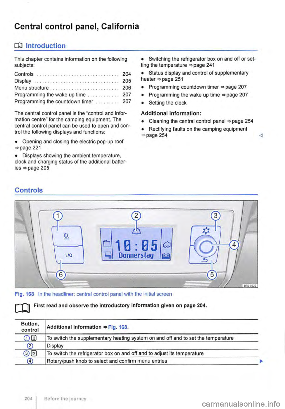
The central control panel is the "control and infor-mation centre" for the camping equipment. The central control panel can be used to open and con-trol the following displays and functions:
• Opening and closing the electric pop-up roof 221
• Displays showing the ambient temperature, clock and charging status of the additional batter-ies 205
Controls
• Switching the refrigerator box on and off or set-ting the temperature =>page 241
• Status display and control of supplementary heater 251
• Programming countdown timer 207
• Programming the wake up time 207
• Setting the clock
Additional information:
• Cleaning the central control panel 254
• Rectifying faults on the camping equipment 254
q Donnerstag g
Fig. 168 In the headliner: central control panel with the initial screen
ro First read and observe the Introductory Information given on page 204.
Button, control
204 I
Additional Information 168.
To switch the supplementary heating system on and off and to set the temperature
Display
To switch the refrigerator box on and off and to adjust its temperature
Rotary/push knob to select and confirm menu entries
Before the journey
Page 205 of 486
Button, control
Display
®
Additional information =>Fig. 168.
To return to initial screen or cancel a setting without saving it
To completely switch off all functions which were activated using the central control panel, e.g. supplementary heating system, refrigerator box, and wake-up time <1
1 9.5 ° c
Fr f."l11 :28
0
Pj
3
0 117H-01S9
First read and observe the introductory lnfonmation given on page 204.
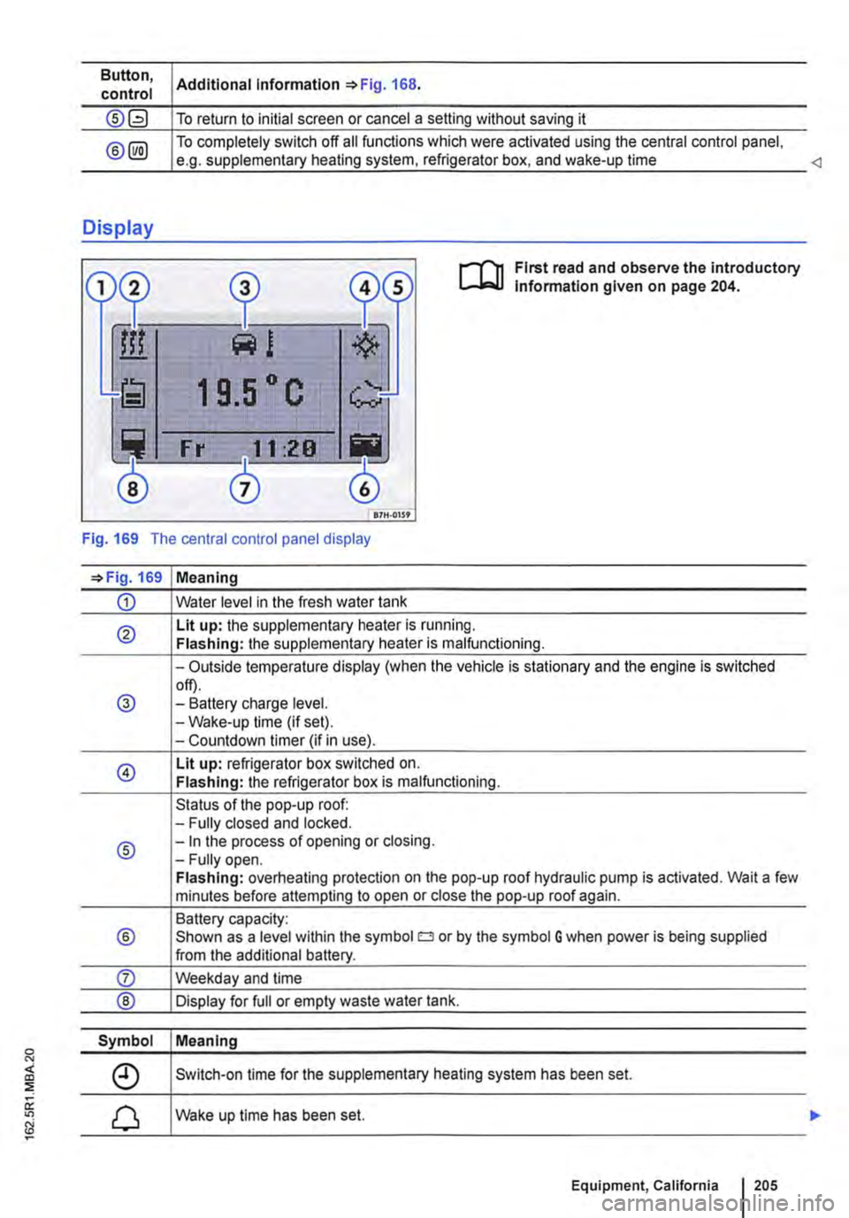
Fig. 169 The central control panel display
=>Fig. 169 Meaning
CD Water level in the fresh water tank
® Lit up: the supplementary heater is running. Flashing: the supplementary heater is malfunctioning.
-Outside temperature display (when the vehicle is stationary and the engine is switched
@ off). -Battery charge level. -Wake-up time (if set). -Countdown timer (if in use).
@ Lit up: refrigerator box switched on. Flashing: the refrigerator box is malfunctioning.
Status of the pop-up roof: -Fully closed and locked.
® -In the process of opening or closing. -Fully open. Flashing: overheating protection on the pop-up roof hydraulic pump is activated. Wait a few minutes before attempting to open or close the pop-up roof again.
Battery capacity:
® Shown as a level within the symbol o or by the symbol G when power is being supplied from the additional battery.
Symbol Meaning
Switch-on time for the supplementary heating system has been set.
Wake up time has been set.
Equipment, California 1205
Page 207 of 486
Main menu Possible functions
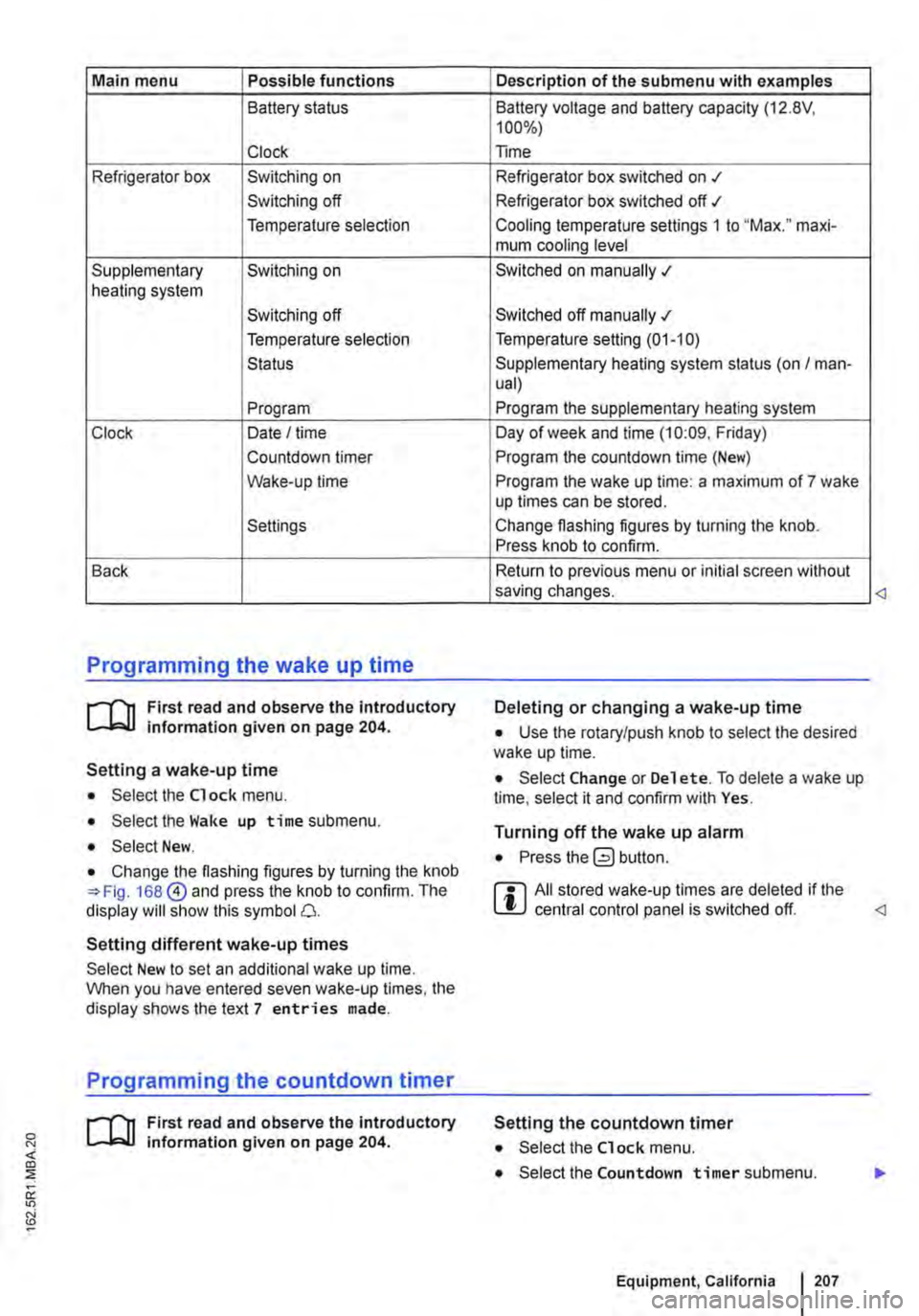
Battery status
Clock
Refrigerator box Switching on
Switching off
Temperature selection
Supplementary Switching on heating system
Switching off
Temperature selection
Status
Program
Clock Date I time
Countdown timer
Wake-up time
Settings
Back
Programming the wake up time
r--f"'n First read and observe the introductory L-lo::.U information given on page 204.
Setting a wake-up time
• Select the Clock menu.
• Select the Wake up time submenu.
• Select New.
• Change the flashing figures by turning the knob 168@ and press the knob to confirm. The display will show this symbol 0.
Setting different wake-up times
Select New to set an additional wake up time. When you have entered seven wake-up times, the display shows the text 7 entries made.
Programming the countdown timer
r--f"'n First read and observe the introductory L-lo::.U information given on page 204.
Description of the submenu with examples
Battery voltage and battery capacity (12.8V, 100%)
Time
Refrigerator box switched on .t
Refrigerator box switched off ./
Cooling temperature settings 1 to "Max." maxi-mum cooling level
Switched on manually .;
Switched off manually .;
Temperature setting (01-10)
Supplementary heating system status (on I man-ual)
Program the supplementary heating system
Day of week and time (10:09. Friday)
Program the countdown time (New)
Program the wake up time: a maximum of 7 wake up times can be stored.
Change flashing figures by turning the knob. Press knob to confirm.
Return to previous menu or initial screen without saving changes.
Deleting or changing a wake-up time
• Use the rotary/push knob to select the desired wake up time.
• Select Change or Del et e. To delete a wake up time, select it and confirm with Yes.
Turning off the wake up alarm
• Press button.
r::l All stored wake-up times are deleted if the L!J central control panel is switched off.
Setting the countdown timer
• Select the Clock menu.
• Select the Countdown timer submenu.
Equipment, California I 207
Page 211 of 486
• Stowage page 1 50
• Cleaning and caring for the interior 388
A WARNING
Loose objects may be flung through the vehi-cle interior in the event of a sudden driving or braking manoeuvre. This can cause serious injury and can also lead to loss of control of the vehicle.
• Do not stow any pets or any hard, heavy or sharp objects in the vehicle's open stow-age compartments, in the luggage net, on the dash panel, on the shelf behind the rear seats or in items of clothing and bags in the vehicle interior.
• Always keep stowage compartments closed while the vehicle is in motion.
A WARNING
Objects in the driver footweli can hinder ped-al operation. This can lead to loss of control of the vehicle and increase the risk of serious injury.
• Please ensure that all pedals can always be operated without any hindrance.
• The foot mats must always be properly se-cured in the footwell.
• No additional foot mats or other floor cov-erings should be placed over the fitted foot mat.
• Ensure that no objects can enter the driv-er footwell while the vehicle is in motion.
• If there are any objects in the footwell, re-move them when the vehicle is parked.
A WARNING
Improper use of the stowage compartments can cause serious injury.
• Never fill stowage compartments beyond their capacity.
A WARNING (Continued)
• Always take care when closing stowage compartments that nobody is within their functional area.
A WARNING
Cigarette lighters in the vehicle could be damaged or accidentally lit. This could lead to serious burns and other injuries.
• Before adjusting the seats always make sure that there is no lighter on or near the moveable parts of the seat.
• Before closing stowage areas or compart-ments always ensure that there is no lighter in the way.
• Never stow lighters in stowage areas or compartments or on other surfaces in the ve-hicle. Cigarette lighters may self-ignite on high-temperature surfaces, especially in sum-mer.
CD
• Hard objects on the shelf can chafe against the wires of the heating element in the rear win-dow and cause damage.
• Do not store any heat-sensitive objects, food or medicines inside the vehicle. Hot and cold temperatures could damage them or ren-der them unusable.
• Objects stored in the vehicle that are made from transparent materials, such as glasses, magnifying glasses or transparent suction cups on the windows, can concentrate the sun's rays and thus cause damage to the vehi-cle.
m Always ensure that the ventilation openings L!J between the rear window and the stowage area are uncovered to allow stale air to escape from the vehicle.
Page 246 of 486
Inserting the Euro plug
• Plug the Euro plug into the Euro socket. The child safety function will disengage at the same time. Electricity will not flow until the child lock has been unlocked.
• Push the Euro plug all the way into the Euro socket so that it is firmly in place and will not fall out as a result of vibration or other vehicle motion.
LEDs above the socket
Constant green light The child lock is disen-gaged. The Euro socket is ready for use.
Flashing red light A fault has occurred. for example cut-off due to excess current or tem-perature.
Compatible devices
Electrical devices with a Euro plug can be connec-ted to the 230-volt Euro socket in the side trim pan-el behind the left front seat.
230-volt grounded safety socket
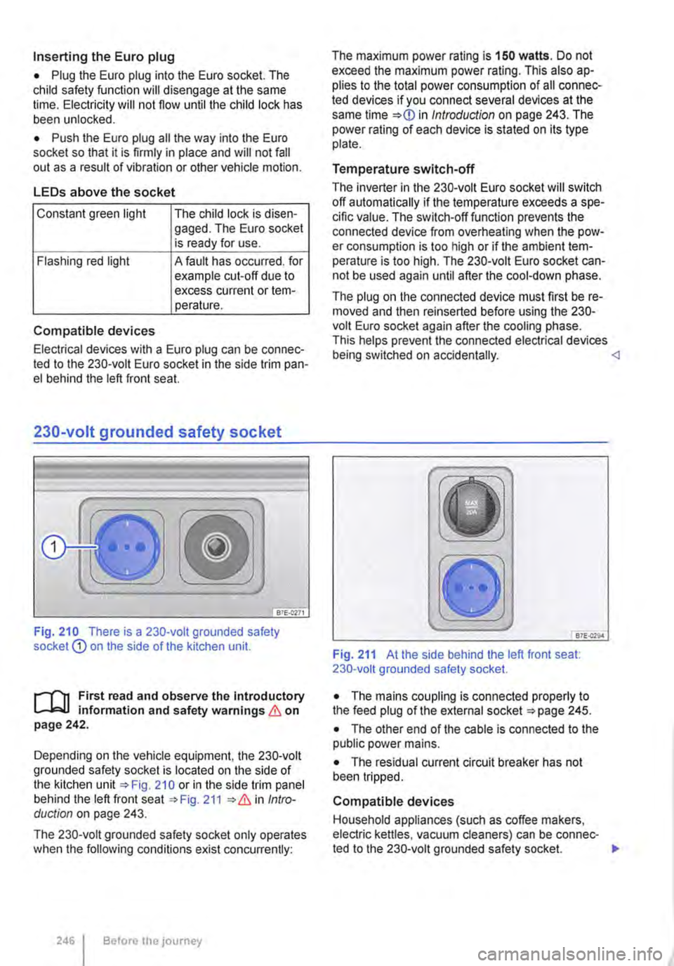
Fig. 210 There is a 230-volt grounded safety socket Q) on the side of the kitchen unit.
r--T'n First read and observe the Introductory L-k.U information and safety warnings & on page 242.
Depending on the vehicle equipment, the 230-volt grounded safety socket is located on the side of the kitchen unit 210 or in the side trim panel behind the left front seat 211 Intro-duction on page 243.
The 230-volt grounded safety socket only operates when the following conditions exist concurrently:
246 I Before the journey
The maximum power rating is 150 watts. Do not exceed the maximum power rating. This also ap-plies to the total power consumption of all connec-ted devices if you connect several devices at the same time in Introduction on page 243. The power rating of each device is stated on its type plate.
Temperature switch-off
The inverter in the 230-volt Euro socket will switch off automatically if the temperature exceeds a spe-cific value. The switch-off function prevents the connected device from overheating when the pow-er consumption is too high or if the ambient tem-perature is too high. The 230-volt Euro socket can-not be used again until after the cool-down phase.
The plug on the connected device must first be re-moved and then reinserted before using the 230-volt Euro socket again after the cooling phase. This helps prevent the connected electrical devices being switched on accidentally. <1
B7E.Q29.4
Fig. 211 At the side behind the left front seat: 230-volt grounded safety socket.
• The mains coupling is connected properly to the feed plug of the external socket 245.
• The other end of the cable is connected to the public power mains.
• The residual current circuit breaker has not been tripped.
Compatible devices
Household appliances (such as coffee makers, electric kettles, vacuum cleaners) can be connec-ted to the 230-volt grounded safety socket. .,.
Page 250 of 486
A WARNING (Continued)
• Never fit fuses that have a higher fuse pro-tection limit. Fuses must always be replaced by a new fuse with the same amp rating (same colour and markings) and size.
• Never repair a fuse.
• Never use a metal strip, paper clip or simi-lar objects to replace a fuse.
CD
• To avoid damage to the electrical system in the vehicle, switch the ignition, the lights and all electrical consumers off and remove the ve-hicle key from the ignition before changing a fuse.
• You can damage another position in the electrical system by using a fuse with a higher amp rating.
• Fuse boxes must be protected from dirt and moisture when opened. Dirt and moisture in the fuse boxes can damage the electrical system.
o::n Introduction
This chapter contains information on the following subjects:
Controls for the living area 250
Controls for the living area
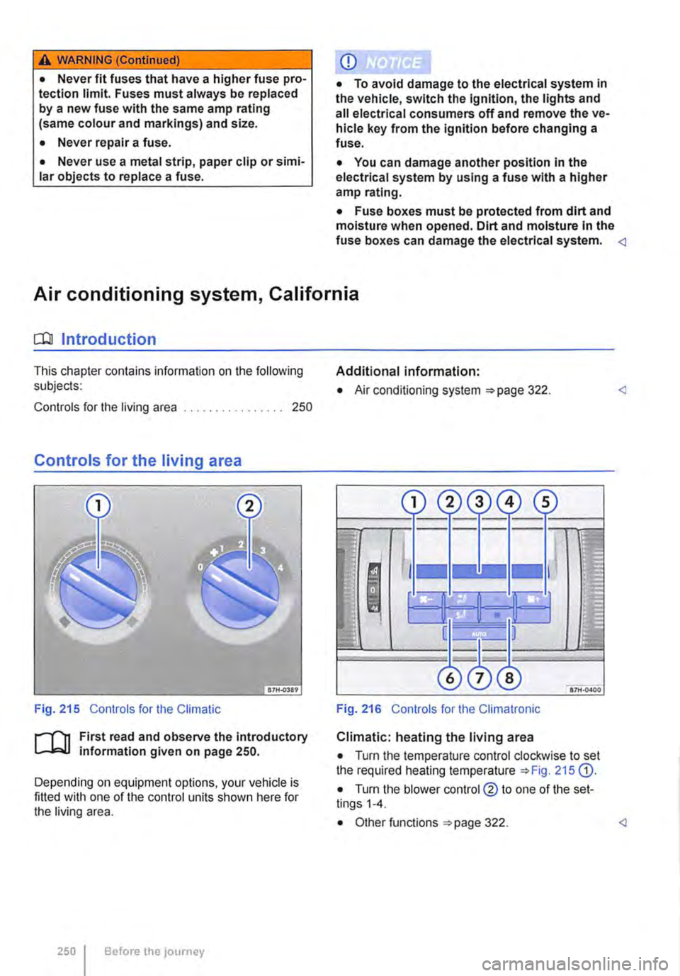
Fig. 215 Controls for the Climatic
ifl1 First read and observe the introductory L-.J.=.IJ information given on page 250.
Depending on equipment options, your vehicle is fitted with one of the control units shown here for the living area.
250 I Before the journey
Additional information:
• Air conditioning system 322.
Fig. 216 Controls for the Climatronic
Climatic: heating the living area
• Turn the temperature control clockwise to set the required heating temperature 215 G).
• Turn the blower control @ to one of the set-tings 1-4.
Page 251 of 486
Supplementary heater, California
o:JJ Introduction
This chapter contains information on the following subjects:
Programming the supplementary heater. . . . . 251
The supplementary heating system is supplied with fuel from the vehicle fuel tank and can be used when the vehicle is in motion or stationary.
Additional information:
• Central control panel 204
• Supplementary heaters 322
• Rectifying faults on the camping equipment 254
A WARNING
The fumes from the supplementary heating system contain carbon monoxide, which is an odourless and colourless poisonous gas. Carbon monoxide can cause people to lose consciousness. lt can also cause death.
A WARNING (Continued)
• Never start or run the supplementary heat-ing system in unventilated or closed rooms.
• Never programme the auxiliary heater so that it is switched on and run in unventilated or enclosed spaces.
A WARNING
Parts of the exhaust system of the supple-mentary heating system become very hot. This can cause fires.
• Park the vehicle so that no part of the ex-haust system can come into contact with any inflammable material underneath the vehicle, e.g. dry grass.
CD
Do not place any food, medicine or any other heat-sensitive items In front of the vents. Heat-sensitive food, medicine and other items could be either damaged or rendered useless.
,.....-('n First read and observe the introductory L-bl.l information and safety warnings & on page 251.
The built-in timer allows you to program up to sev-en switch-on times.
Functions Submenu Description
New Set daily or day of Turn the rotary/push knob 168@ to change the setting. week. Press the rotary/push knob to confirm the setting and move to the next submenu.
Set the time Set the switch-on time.
Specify the run period. Set the run period for the supplementary heating system. A low battery charge could cause the run period to be cut short.
Select temperature. Select the heating temperature.
Change Change switch-on time. Select the switch-on setting to be changed and select Change. Change the switch-on time as described under New.
Delete Delete switch-on time. Select the switch-on time to be deleted and select Delete. Con-firm entry.
Equipment, California I 251