2013 SUBARU FORESTER ECO mode
[x] Cancel search: ECO modePage 362 of 436
WARNING
Never let clutch fluid contact your
eyes because clutch fluid can be
harmful to your eyes. If clutch fluid
gets in your eyes, immediately flush
them thoroughly with clean water.
For safety, wearing eye protection isadvisable.
CAUTION
. Clutch fluid absorbs moisture
from the air. Any absorbed moist-
ure can cause improper clutchoperation.
. If the vehicle requires frequent
refilling, there may be a leak. If
you suspect a problem, have the
vehicle checked at your SUBARU
dealer.
. When clutch fluid is added, be
careful not to allow any dirt into
the tank.
. Never splash the clutch fluid over
painted surfaces or rubber parts.
Alcohol contained in the clutch
fluid may damage them.
. Be careful not to spill clutch fluid
when adding it. If clutch fluid
touches the exhaust pipe, it may cause a bad smell, smoke, and/or
a fire. If clutch fluid gets on the
exhaust pipe, be sure to wipe itoff.
& Recommended clutch fluid
Refer to “Fluids ”F 12-9.
CAUTION
Never use different brands of clutch
fluid together. Also, avoid mixing
DOT 3 and DOT 4 brake fluids even if
they are the same brand. Brake booster
If the brake booster does not operate as
described in the following, have it checked
by your SUBARU dealer.
1. With the engine off, depress the brake
pedal several times, applying the same
pedal force each time. The distance the
pedal travels should not vary.
2. With the brake pedal depressed, start
the engine. The pedal should move
slightly down to the floor.
3. With the brake pedal depressed, stop
the engine and keep the pedal depressed
for 30 seconds. The pedal height should
not change.
4. Start the engine again and run for
approximately 1 minute then turn it off.
Depress the brake pedal several times to
check the brake booster. The brake
booster operates properly if the pedal
stroke decreases with each depression. NOTE
For models equipped with the brake
assist system, when you depress the
brake pedal strongly or suddenly while
the engine is running, the following
phenomena occur. They do not indicate
any malfunctions, and the brake assist
system is operating properly.Maintenance and service
11-25
– CONTINUED –
Page 366 of 436
Parking brake stroke
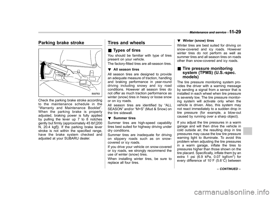
Check the parking brake stroke according
to the maintenance schedule in the“Warranty and Maintenance Booklet ”.
When the parking brake is properly
adjusted, braking power is fully applied
by pulling the lever up 7 to 8 notches
gently but firmly (approximately 45 lbf [200
N, 20.4 kgf]). If the parking brake lever
stroke is not within the specified range,
have the brake system checked and
adjusted at your SUBARU dealer. Tires and wheels &
Types of tires
You should be familiar with type of tires
present on your vehicle.
The factory-fitted tires are all-season tires. ! All season tires
All season tires are designed to provide
an adequate measure of traction, handling
and braking performance in year-round
driving including snowy and icy road
conditions. However all season tires do
not offer as much traction performance as
winter (snow) tires in heavy or loose snow
or on icy roads.
All season tires are identified by “ALL
SEASON ”and/or “M+S ”(Mud & Snow) on
the tire sidewall. ! Summer tires
Summer tires are high-speed capability
tires best suited for highway driving under
dry conditions.
Summer tires are inadequate for driving
on slippery roads such as on snow-
covered or icy roads.
If you drive your vehicle on snow-covered
or icy roads, we strongly recommend the
use of winter (snow) tires.
When installing winter tires, be sure to
replace all four tires. !
Winter (snow) tires
Winter tires are best suited for driving on
snow-covered and icy roads. However
winter tires do not perform as well as
summer tires and all season tires on roads
other than snow-covered and icy roads. & Tire pressure monitoring
system (TPMS) (U.S.-spec.models)
The tire pressure monitoring system pro-
vides the driver with a warning message
by sending a signal from a sensor that is
installed in each wheel when tire pressure
is severely low. The tire pressure monitor-
ing system will activate only when the
vehicle is driven. Also, this system may
not react immediately to a sudden drop in
tire pressure (for example, a blow-out
caused by running over a sharp object).
If you adjust the tire pressures in a warm
garage and will then drive the vehicle in
cold outside air, the resulting drop in tire
pressures may cause the low tire pressure
warning light to illuminate. To avoid this
problem when adjusting the tire pressures
in a warm garage, inflate the tires to
pressures higher than those shown on the
tire placard. Specifically, inflate them by an
extra 1 psi (6.9 kPa, 0.07 kgf/cm
2) for
every difference of 10 8F (5.6 8C) between
Maintenance and service
11-29
– CONTINUED –
Page 372 of 436
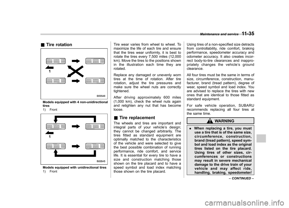
&Tire rotation
Models equipped with 4 non-unidirectional tires
1) Front
Models equipped with unidirectional tires
1) Front Tire wear varies from wheel to wheel. To
maximize the life of each tire and ensure
that the tires wear uniformly, it is best to
rotate the tires every 7,500 miles (12,000
km). Move the tires to the positions shown
in the illustration each time they arerotated.
Replace any damaged or unevenly worn
tires at the time of rotation. After tire
rotation, adjust the tire pressures and
make sure the wheel nuts are correctlytightened.
After driving approximately 600 miles
(1,000 km), check the wheel nuts again
and retighten any nut that has becomeloose. &
Tire replacement
The wheels and tires are important and
integral parts of your vehicle ’s design;
they cannot be changed arbitrarily. The
tires fitted as standard equipment are
optimally matched to the characteristics
of the vehicle and were selected to give
the best possible combination of running
performance, ride comfort, and service
life. It is essential for every tire to have a
size and construction matching those
shown on the tire placard and to have a
speed symbol and load index matching
those shown on the tire placard. Using tires of a non-specified size detracts
from controllability, ride comfort, braking
performance, speedometer accuracy and
odometer accuracy. It also creates incor-
rect body-to-tire clearances and inappro-
priately changes the vehicle
’s ground
clearance.
All four tires must be the same in terms of
size, circumference, construction, manu-
facturer, brand (tread pattern), degree of
wear, speed symbol and load index. You
are advised to replace the tires with new
ones that are identical to those fitted as
standard equipment.
For safe vehicle operation, SUBARU
recommends replacing all four tires at
the same time.
WARNING
. When replacing a tire, you must
use a tire that is of the same size,
circumference, construction,
brand (tread pattern), speed sym-
bol and load index as the original
tires listed on the tire placard.
Using tires of other sizes, cir-
cumferences or constructions
may result in severe mechanical
damage to the drive train of your
vehicle and may affect ride,
handling, braking, speedometer/ Maintenance and service
11-35
– CONTINUED –
Page 382 of 436

corresponding fuse. If a fuse has blown,
replace it.
1. Turn the ignition switch to the“LOCK ”
position and turn off all electrical acces- sories.
2. Remove the cover.
3. Determine which fuse may be blown.
Look at the back side of each fuse box
cover and refer to “Fuses and circuits ”
F 12-11.
4. Pull out the fuse with the fuse puller.
5. Inspect the fuse. If it has blown,
replace it with a spare fuse of the samerating.
6. If the same fuse blows again, this
indicates that its system has a problem.
Contact your SUBARU dealer for repairs. Installation of accessories
Always consult your SUBARU dealer
before installing fog lights or any other
electrical equipment in your vehicle. Such
accessories may cause the electronic
system to malfunction if they are incor-
rectly installed or if they are not suited for
the vehicle.
Replacing bulbs
WARNING
Bulbs may become very hot while
illuminated. Before replacing bulbs,
turn off the lights and wait until the
bulbs cool down. Otherwise, there is
a risk of burn injury.
CAUTION
Replace any bulb only with a new
bulb of the specified wattage. Using
a bulb of different wattage could
result in a fire. For the specified
wattage of each bulb, refer to “Bulb
chart ”F 12-15.
& Headlights (models with HID headlights)
WARNING
High-intensity-discharge (HID) bulbs
are used for the low beams of the
headlights. These HID bulbs use an
extremely high voltage. To avoid the
risk of an electric shock that could
result in serious injury, observe the Maintenance and service
11-45
– CONTINUED –
Page 383 of 436

11-46Maintenance and service
following precautions. .Do not replace any headlight
bulbs (both low beam and high
beam) by yourself.
. Do not remove/restore the head-
light assemblies by yourself.
. Do not remove any headlight-
assembly components by your-self.
For replacement, contact your
SUBARU dealer.
& Headlights (models without
HID headlights)
CAUTION
Halogen headlight bulbs become
very hot while in use. If you touch
the bulb surface with bare hands or
greasy gloves, fingerprints or
grease on the bulb surface will
develop into hot spots, causing the
bulb to break. If there are finger
prints or grease on the bulb surface,
wipe them away with a soft cloth
moistened with alcohol. NOTE .
If headlight aiming is required, con-
sult your SUBARU dealer for proper adjustment.. It may be difficult to replace the
bulbs. Have the bulbs replaced by your
SUBARU dealer if necessary. !
Low beam light bulbs
Right-hand side
1. Use a screwdriver to undo the clips on
the air intake duct, then remove the air
intake duct (right-hand side).
Left-hand side
Page 402 of 436
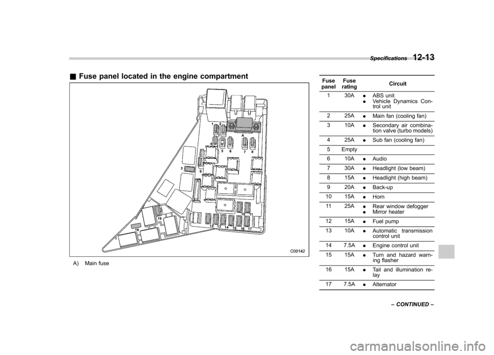
&Fuse panel located in the engine compartment
A) Main fuse Fuse
panel Fuse
rating Circuit
1 30A .ABS unit
. Vehicle Dynamics Con-
trol unit
2 25A .Main fan (cooling fan)
3 10A .Secondary air combina-
tion valve (turbo models)
4 25A .Sub fan (cooling fan)
5 Empty
6 10A .Audio
7 30A .Headlight (low beam)
8 15A .Headlight (high beam)
9 20A .Back-up
10 15A .Horn
11 25A .Rear window defogger
. Mirror heater
12 15A .Fuel pump
13 10A .Automatic transmission
control unit
14 7.5A .Engine control unit
15 15A .Turn and hazard warn-
ing flasher
16 15A .Tail and illumination re-
lay
17 7.5A .Alternator
Specifications
12-13
– CONTINUED –
Page 405 of 436
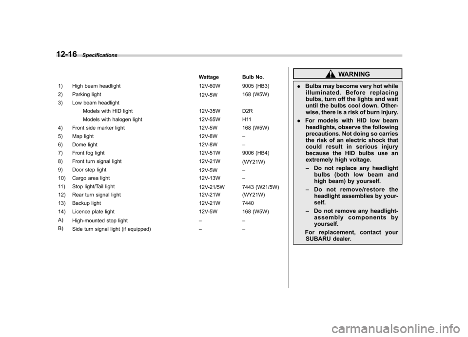
12-16Specifications
Wattage Bulb No.
1) High beam headlight 12V-60W 9005 (HB3)
2) Parking light 12V-5W168 (W5W)
3) Low beam headlight
Models with HID light 12V-35W D2R
Models with halogen light 12V-55W H11
4) Front side marker light 12V-5W 168 (W5W)
5) Map light 12V-8W–
6) Dome light 12V-8W–
7) Front fog light 12V-51W 9006 (HB4)
8) Front turn signal light 12V-21W (WY21W)
9) Door step light 12V-5W–
10) Cargo area light 12V-13W–
11) Stop light/Tail light 12V-21/5W 7443 (W21/5W)
12) Rear turn signal light 12V-21W (WY21W)
13) Backup light 12V-21W 7440
14) Licence plate light 12V-5W 168 (W5W)A) High-mounted stop light ––
B) Side turn signal light (if equipped) ––WARNING
. Bulbs may become very hot while
illuminated. Before replacing
bulbs, turn off the lights and wait
until the bulbs cool down. Other-
wise, there is a risk of burn injury.
. For models with HID low beam
headlights, observe the following
precautions. Not doing so carries
the risk of an electric shock that
could result in serious injury
because the HID bulbs use an
extremely high voltage. – Do not replace any headlight
bulbs (both low beam and
high beam) by yourself.
– Do not remove/restore the
headlight assemblies by your-self.
– Do not remove any headlight-
assembly components by yourself.
For replacement, contact your SUBARU dealer.
Page 413 of 436
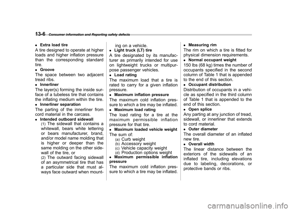
13-6Consumer information and Reporting safety defects
. Extra load tire
A tire designed to operate at higher
loads and higher inflation pressure
than the corresponding standardtire. . Groove
The space between two adjacent
tread ribs.. Innerliner
The layer(s) forming the inside sur-
face of a tubeless tire that contains
the inflating medium within the tire. . Innerliner separation
The parting of the innerliner from
cord material in the carcass.. Intended outboard sidewall
(1) The sidewall that contains a
whitewall, bears white lettering
or bears manufacturer, brand,
and/or model name molding that
is higher or deeper than the
same molding on the other side-
wall of the tire, or (2) The outward facing sidewall
of an asymmetrical tire that has
a particular side that must al-
ways face outward when mount- ing on a vehicle.
. Light truck (LT) tire
A tire designated by its manufac-
turer as primarily intended for use
on lightweight trucks or multipur-
pose passenger vehicles. . Load rating
The maximum load that a tire is
rated to carry for a given inflationpressure.. Maximum inflation pressure
The maximum cold inflation pres-
sure to which a tire may be inflated.. Maximum load rating
The load rating for a tire at the
maximum permissible inflation
pressure for that tire.. Maximum loaded vehicle weight
The sum of: (a) Curb weight
(b) Accessory weight
(c) Vehicle capacity weight
(d) Production options weight
. Maximum permissible inflation
pressure
The maximum cold inflation pres-
sure to which a tire may be inflated. .
Measuring rim
The rim on which a tire is fitted for
physical dimension requirements. . Normal occupant weight
150 lbs (68 kg) times the number of
occupants specified in the second
column of Table 1 that is appended
to the end of this section. . Occupant distribution
Distribution of occupants in a vehi-
cle as specified in the third column
of Table 1 that is appended to the
end of this section. . Open splice
Any parting at any junction of tread,
sidewall, or innerliner that extends
to cord material. . Outer diameter
The overall diameter of an inflated
new tire.. Overall width
The linear distance between the
exteriors of the sidewalls of an
inflated tire, including elevations
due to labeling, decorations, or
protective bands or ribs.