Page 321 of 436

9-8In case of emergency
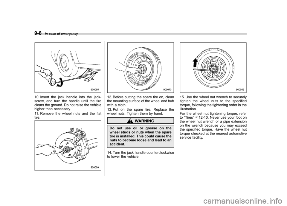
10. Insert the jack handle into the jack-
screw, and turn the handle until the tire
clears the ground. Do not raise the vehicle
higher than necessary.
11. Remove the wheel nuts and the flat tire.12. Before putting the spare tire on, clean
the mounting surface of the wheel and hub
with a cloth.
13. Put on the spare tire. Replace the
wheel nuts. Tighten them by hand.
WARNING
Do not use oil or grease on the
wheel studs or nuts when the spare
tire is installed. This could cause the
nuts to become loose and lead to anaccident.
14. Turn the jack handle counterclockwise
to lower the vehicle.
15. Use the wheel nut wrench to securely
tighten the wheel nuts to the specified
torque, following the tightening order in theillustration.
For the wheel nut tightening torque, refer to “Tires ”F 12-10. Never use your foot on
the wheel nut wrench or a pipe extension
on the wrench because you may exceed
the specified torque. Have the wheel nut
torque checked at the nearest automotive
service facility.
Page 326 of 436

Engine overheating
WARNING
Never attempt to remove the radia-
tor cap until the engine has been
shut off and has fully cooled down.
When the engine is hot, the coolant
is under pressure. Removing the
cap while the engine is still hot
could release a spray of boiling hot
coolant, which could burn you very
seriously.
If the engine overheats, safely pull off the
road and stop the vehicle in a safe place. & If steam is coming from the
engine compartment
Turn off the engine and get everyone
away from the vehicle until it cools down. & If no steam is coming from
the engine compartment
NOTE
For details about how to check the
coolant level or how to add coolant,
refer to “Engine coolant ”F 11-14.
1. Keep the engine running at idlingspeed. 2. Open the hood to ventilate the engine
compartment. Refer to
“Engine hood ”
F 11-5.
Confirm that the cooling fan is turning. If
the fan is not turning, immediately turn off
the engine and contact your SUBARU
dealer for repair.
3. After the engine coolant temperature
has dropped, turn off the engine.
If any of the following conditions occur,
turn off the engine. .The temperature gauge stays in the
overheated zone (if equipped). Referto “Temperature gauge (models with
type A combination meter) ”F 3-11.
. The coolant temperature high warn-
ing light remains illuminated (if
equipped). Refer to “Coolant tempera-
ture low indicator light/Coolant tem-
perature high warning light ”F 3-16.
4. After the engine has fully cooled down,
check the coolant level in the reservoir.
If the coolant level is below the “LOW ”
mark, add coolant up to the “FULL ”mark.
5. If there is no coolant in the reservoir,
add coolant to the reservoir. Then remove
the radiator cap (non-turbo models) or the
coolant filler tank cap (turbo models) and
fill the radiator with coolant.
If you have to remove a hot radiator cap/
coolant filler tank cap, first wrap a thick cloth around the cap, then turn the cap
counterclockwise slowly without pressing
down until it stops. Release the pressure
from the cooling system. After the pres-
sure has been fully released, remove the
cap by pressing it down and turningcounterclockwise.
In case of emergency
9-13
Page 378 of 436
&Rear window wiper blade assembly
1. Raise the wiper arm off the rear
window.
2. Turn the wiper blade assembly coun- terclockwise.
3. Pull the wiper blade assembly toward
you to remove it from the wiper arm.
4. Install the wiper blade assembly to the
wiper arm. Make sure that it locks in place.
5. Hold the wiper arm by hand and slowly
lower it in position. &
Rear window wiper blade rubber
1. Pull out the end of the blade rubber
assembly to unlock it from the plasticsupport.
Maintenance and service 11-41
– CONTINUED –
Page 384 of 436
2. Use a Phillips screwdriver to remove
the secured clip of the washer tank. To
make it easy to access the bulb, move the
washer tank to the horizontal direction
(left-hand side).
3. Remove the bulb cover by turning it counterclockwise.
4. Disconnect the electrical connector
from the bulb.
5. Remove the bulb from the headlight
assembly by turning it counterclockwise.
6. Replace the bulb with a new one. At
this time, do not touch the bulb surface.7. To install the bulb to the headlight
assembly, turn it clockwise until it clicks.
8. Reconnect the electrical connector.
9. Install the bulb cover.
10. Install the air intake duct with clips
(right-hand side).
11. Set the washer tank to the original
place and secure it by clip (left-hand side). !
High beam light bulbs
Right-hand side
1. Use a screwdriver to undo the clips on
the air intake duct, then remove the air
intake duct (right-hand side). Maintenance and service
11-47
– CONTINUED –
Page 385 of 436
11-48Maintenance and service
2. Disconnect the electrical connector
from the bulb.
3. Remove the bulb from the headlight
assembly by turning it counterclockwise.
4. Replace the bulb with new one. At this
time, be careful not to touch the bulb surface. Turn the bulb clockwise until itclicks.
5. Reconnect the electrical connector.
6. Install the air intake duct with clips
(right-hand side).
& Parking light
1. Turn the bulb socket counterclockwise
and pull out the socket.
2. Pull the bulb out of the socket.
3. Install a new bulb.
4. Install the bulb socket by turning it clockwise. &
Front turn signal light
It may be difficult to replace the bulbs.
Have the bulbs replaced by your SUBARU
dealer if necessary. & Rear combination lights1. Using a Phillips screwdriver, remove
the upper and lower screws that secure
the rear combination light assembly.
Page 386 of 436
2. Slide the rear combination light as-
sembly rearward and remove it from thevehicle.
1) Stop light/Tail light
2) Rear turn signal light
3) Backup light3. Remove the bulb socket from the rear
combination light assembly by turning itcounterclockwise.
4. Pull the bulb out of the bulb socket and
replace it with a new one.
5. Set the bulb socket into the rear
combination light assembly and turn it
clockwise until it locks.
6. Put the rear combination light assem-
bly into place while aligning the clip with
the guide on the vehicle.
7. Tighten the upper and lower screws. &
License plate light
1. Remove the mounting screws using a
Phillips screwdriver. Maintenance and service
11-49
– CONTINUED –
Page 400 of 436
Fuses and circuits &Fuse panel located in the passenger compartmentFuse
panel Fuse
rating Circuit
1 20A .Trailer
2 Empty
3 15A .Door locking
4 10A .Front wiper deicer relay
5 10A .Combination meter
6 7.5A .Remote control rear
view mirrors
. Seat heater relay
7 15A .Combination meter
. Integrated unit
8 20A .Stop light
9 15A .Front wiper deicer
10 7.5A .Power supply (battery)
11 7.5A .Turn signal unit
. Clock
12 15A .Automatic transmission
unit
. Engine control unit
. Integrated unit
13 20A .Accessory power outlet
(center console)
14 15A .Parking light
. Tail light
. Rear combination light
15 Empty (FWD connector for AWD AT models)
Specifications
12-11
– CONTINUED –
Page 401 of 436
12-12Specifications
Fuse
panel Fuse
rating Circuit
16 10A .Illumination
17 15A .Seat heaters
18 10A .Backup light
19 Empty
20 10A .Accessory power outlet
(instrument panel)
21 7.5A .Starter relay
22 15A .Air conditioner
. Rear window defogger
relay coil
23 15A .Rear wiper
. Rear window washer
24 15A .Audio unit
. Clock
25 15A .SRS airbag system
26 7.5A .Power window relay
. Radiator main fan relay
. Tail and illumination re-
lay
27 15A .Blower fan
28 15A .Blower fan
29 15A .Fog light
30 30A .Front wiper
31 7.5A .Auto air conditioner unit
. Integrated unit Fuse
panel Fuse
rating Circuit
32 Empty
33 7.5A .ABS/Vehicle Dynamics
Control unit