2013 SUBARU FORESTER low beam
[x] Cancel search: low beamPage 303 of 436
8-16Driving tips
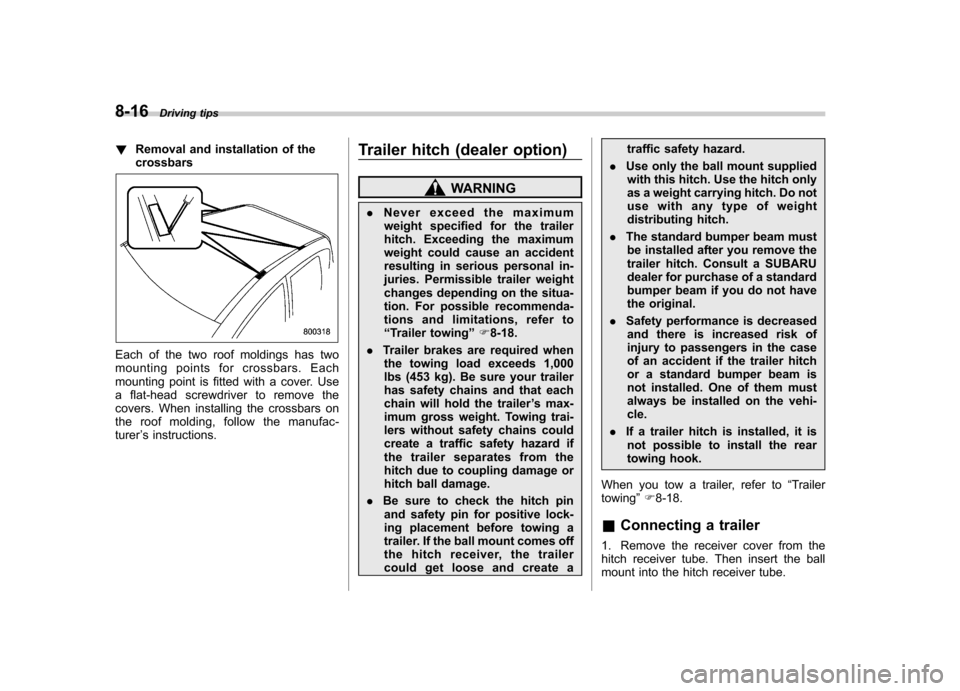
!Removal and installation of the crossbars
Each of the two roof moldings has two
mounting points for crossbars. Each
mounting point is fitted with a cover. Use
a flat-head screwdriver to remove the
covers. When installing the crossbars on
the roof molding, follow the manufac- turer ’s instructions. Trailer hitch (dealer option)
WARNING
. Never exceed the maximum
weight specified for the trailer
hitch. Exceeding the maximum
weight could cause an accident
resulting in serious personal in-
juries. Permissible trailer weight
changes depending on the situa-
tion. For possible recommenda-
tions and limitations, refer to“ Trailer towing ”F 8-18.
. Trailer brakes are required when
the towing load exceeds 1,000
lbs (453 kg). Be sure your trailer
has safety chains and that each
chain will hold the trailer ’s max-
imum gross weight. Towing trai-
lers without safety chains could
create a traffic safety hazard if
the trailer separates from the
hitch due to coupling damage or
hitch ball damage.
. Be sure to check the hitch pin
and safety pin for positive lock-
ing placement before towing a
trailer. If the ball mount comes off
the hitch receiver, the trailer
could get loose and create a traffic safety hazard.
. Use only the ball mount supplied
with this hitch. Use the hitch only
as a weight carrying hitch. Do not
use with any type of weight
distributing hitch.
. The standard bumper beam must
be installed after you remove the
trailer hitch. Consult a SUBARU
dealer for purchase of a standard
bumper beam if you do not have
the original.
. Safety performance is decreased
and there is increased risk of
injury to passengers in the case
of an accident if the trailer hitch
or a standard bumper beam is
not installed. One of them must
always be installed on the vehi-cle.
. If a trailer hitch is installed, it is
not possible to install the rear
towing hook.
When you tow a trailer, refer to “Trailer
towing ”F 8-18.
& Connecting a trailer
1. Remove the receiver cover from the
hitch receiver tube. Then insert the ball
mount into the hitch receiver tube.
Page 328 of 436
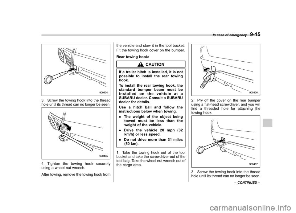
3. Screw the towing hook into the thread
hole until its thread can no longer be seen.
4. Tighten the towing hook securely
using a wheel nut wrench.
After towing, remove the towing hook fromthe vehicle and stow it in the tool bucket.
Fit the towing hook cover on the bumper.
Rear towing hook:
CAUTION
If a trailer hitch is installed, it is not
possible to install the rear towinghook.
To install the rear towing hook, the
standard bumper beam must be
installed on the vehicle at a
SUBARU dealer. Consult a SUBARU
dealer for details.
Use a hitch ball and follow the
instructions below when towing. . The weight of the object being
towed must be less than the
weight of the vehicle.
. Drive the vehicle 20 mph (32
km/h) or less speed.
. Do not drive more than 31 miles
(50 km).
1. Take the towing hook out of the tool
bucket and take the screwdriver out of the
tool bag. Take the wheel nut wrench out of
the cargo area.
2. Pry off the cover on the rear bumper
using a flat-head screwdriver, and you will
find a threaded hole for attaching the
towing hook.
3. Screw the towing hook into the thread
hole until its thread can no longer be seen. In case of emergency
9-15
– CONTINUED –
Page 382 of 436

corresponding fuse. If a fuse has blown,
replace it.
1. Turn the ignition switch to the“LOCK ”
position and turn off all electrical acces- sories.
2. Remove the cover.
3. Determine which fuse may be blown.
Look at the back side of each fuse box
cover and refer to “Fuses and circuits ”
F 12-11.
4. Pull out the fuse with the fuse puller.
5. Inspect the fuse. If it has blown,
replace it with a spare fuse of the samerating.
6. If the same fuse blows again, this
indicates that its system has a problem.
Contact your SUBARU dealer for repairs. Installation of accessories
Always consult your SUBARU dealer
before installing fog lights or any other
electrical equipment in your vehicle. Such
accessories may cause the electronic
system to malfunction if they are incor-
rectly installed or if they are not suited for
the vehicle.
Replacing bulbs
WARNING
Bulbs may become very hot while
illuminated. Before replacing bulbs,
turn off the lights and wait until the
bulbs cool down. Otherwise, there is
a risk of burn injury.
CAUTION
Replace any bulb only with a new
bulb of the specified wattage. Using
a bulb of different wattage could
result in a fire. For the specified
wattage of each bulb, refer to “Bulb
chart ”F 12-15.
& Headlights (models with HID headlights)
WARNING
High-intensity-discharge (HID) bulbs
are used for the low beams of the
headlights. These HID bulbs use an
extremely high voltage. To avoid the
risk of an electric shock that could
result in serious injury, observe the Maintenance and service
11-45
– CONTINUED –
Page 383 of 436

11-46Maintenance and service
following precautions. .Do not replace any headlight
bulbs (both low beam and high
beam) by yourself.
. Do not remove/restore the head-
light assemblies by yourself.
. Do not remove any headlight-
assembly components by your-self.
For replacement, contact your
SUBARU dealer.
& Headlights (models without
HID headlights)
CAUTION
Halogen headlight bulbs become
very hot while in use. If you touch
the bulb surface with bare hands or
greasy gloves, fingerprints or
grease on the bulb surface will
develop into hot spots, causing the
bulb to break. If there are finger
prints or grease on the bulb surface,
wipe them away with a soft cloth
moistened with alcohol. NOTE .
If headlight aiming is required, con-
sult your SUBARU dealer for proper adjustment.. It may be difficult to replace the
bulbs. Have the bulbs replaced by your
SUBARU dealer if necessary. !
Low beam light bulbs
Right-hand side
1. Use a screwdriver to undo the clips on
the air intake duct, then remove the air
intake duct (right-hand side).
Left-hand side
Page 402 of 436
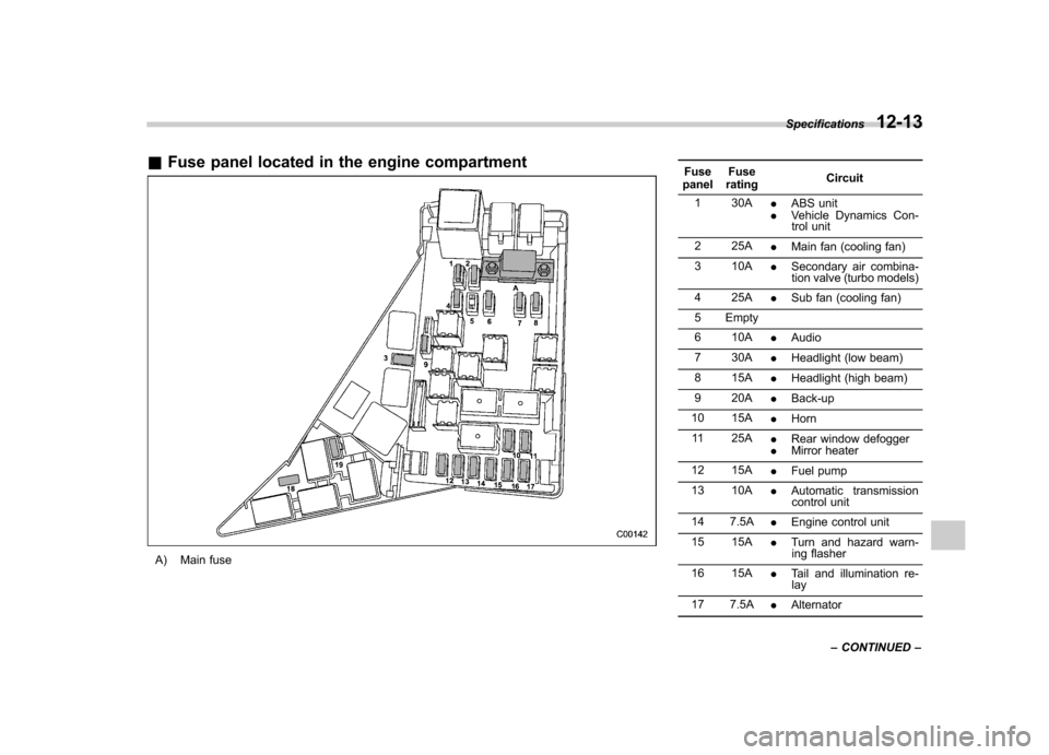
&Fuse panel located in the engine compartment
A) Main fuse Fuse
panel Fuse
rating Circuit
1 30A .ABS unit
. Vehicle Dynamics Con-
trol unit
2 25A .Main fan (cooling fan)
3 10A .Secondary air combina-
tion valve (turbo models)
4 25A .Sub fan (cooling fan)
5 Empty
6 10A .Audio
7 30A .Headlight (low beam)
8 15A .Headlight (high beam)
9 20A .Back-up
10 15A .Horn
11 25A .Rear window defogger
. Mirror heater
12 15A .Fuel pump
13 10A .Automatic transmission
control unit
14 7.5A .Engine control unit
15 15A .Turn and hazard warn-
ing flasher
16 15A .Tail and illumination re-
lay
17 7.5A .Alternator
Specifications
12-13
– CONTINUED –
Page 405 of 436
12-16Specifications
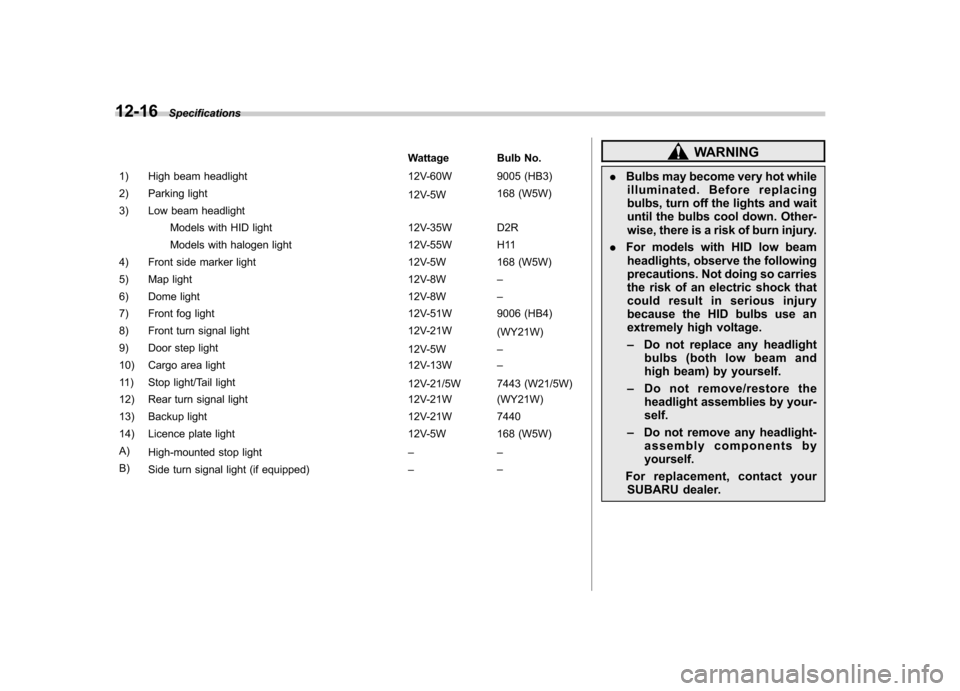
Wattage Bulb No.
1) High beam headlight 12V-60W 9005 (HB3)
2) Parking light 12V-5W168 (W5W)
3) Low beam headlight
Models with HID light 12V-35W D2R
Models with halogen light 12V-55W H11
4) Front side marker light 12V-5W 168 (W5W)
5) Map light 12V-8W–
6) Dome light 12V-8W–
7) Front fog light 12V-51W 9006 (HB4)
8) Front turn signal light 12V-21W (WY21W)
9) Door step light 12V-5W–
10) Cargo area light 12V-13W–
11) Stop light/Tail light 12V-21/5W 7443 (W21/5W)
12) Rear turn signal light 12V-21W (WY21W)
13) Backup light 12V-21W 7440
14) Licence plate light 12V-5W 168 (W5W)A) High-mounted stop light ––
B) Side turn signal light (if equipped) ––WARNING
. Bulbs may become very hot while
illuminated. Before replacing
bulbs, turn off the lights and wait
until the bulbs cool down. Other-
wise, there is a risk of burn injury.
. For models with HID low beam
headlights, observe the following
precautions. Not doing so carries
the risk of an electric shock that
could result in serious injury
because the HID bulbs use an
extremely high voltage. – Do not replace any headlight
bulbs (both low beam and
high beam) by yourself.
– Do not remove/restore the
headlight assemblies by your-self.
– Do not remove any headlight-
assembly components by yourself.
For replacement, contact your SUBARU dealer.
Page 425 of 436

14-2Index
A Abbreviation ................................................................... 3
ABS (Anti-lock Brake System) ..................................... 7-23
Warning light ......................................................... 3-19
Accessories ....................................................... 5-4, 11-45
Accessory power outlet ................................................. 6-9
Active head restraint ..................................................... 1-6
Air cleaner element ................................................... 11-15
Air conditioner
Manual climate control system ................................... 4-8
Air filtration system ..................................................... 4-11
Airflow selection Automatic climate control system ............................... 4-6
Manual climate control system ................................... 4-8
Alarm system ............................................................ 2-14
All-Wheel Drive warning light ....................................... 3-21
Aluminum wheel ....................................................... 11-37
Cleaning ............................................................... 10-3
Antenna system ........................................................... 5-3
Anti-lock Brake System (ABS) ..................................... 7-23
Arming the system ..................................................... 2-15
Armrest ....................................................................... 1-8
Ashtray ..................................................................... 6-11
AT OIL TEMP warning light ......................................... 3-17
Audio Antenna system ....................................................... 5-3
Auxiliary input jack ................................................. 5-29
Bluetooth
®audio .................................................... 5-40
CD player operation ............................................... 5-22
Control button ........................................................ 5-37
FM/AM radio operation ........................................... 5-13 iPod
®operations
.................................................... 5-32
Power and audio controls ......................................... 5-9
Satellite radio operations ......................................... 5-18
Set ........................................................................ 5-4
USB storage device operations ................................ 5-32
Auto-dimming mirror/compass .............................. 3-36, 3-38
Automatic climate control system ................................... 4-6
Automatic headlight beam leveler ................................. 3-31
Warning light .......................................................... 3-21
Automatic transmission ............................................... 7-15
Fluid ........................................................... 11-20, 12-9
MANUAL mode ...................................................... 7-19
Oil temperature warning light (AT OIL TEMP) ............. 3-17
Select lever ........................................................... 7-16
Shift lock function ................................................... 7-17
SPORT mode ........................................................ 7-20
Automatic/Emergency Locking Retractor (A/ELR) ........... 1-13
Auxiliary input jack ...................................................... 5-29
BBattery .................................................................... 11-43
Drainage prevention function ..................................... 2-5
Jump starting ......................................................... 9-10
Replacement (remote engine start transmitter) ........... 7-12
Replacement (remote keyless entry system) .............. 2-10
Bluetooth
®audio ........................................................ 5-40
Booster seat .............................................................. 1-28
Bottle holder ............................................................... 6-9
Brake Assist .................................................................... 7-22
Booster ....................................................... 7-22, 11-25
Page 429 of 436
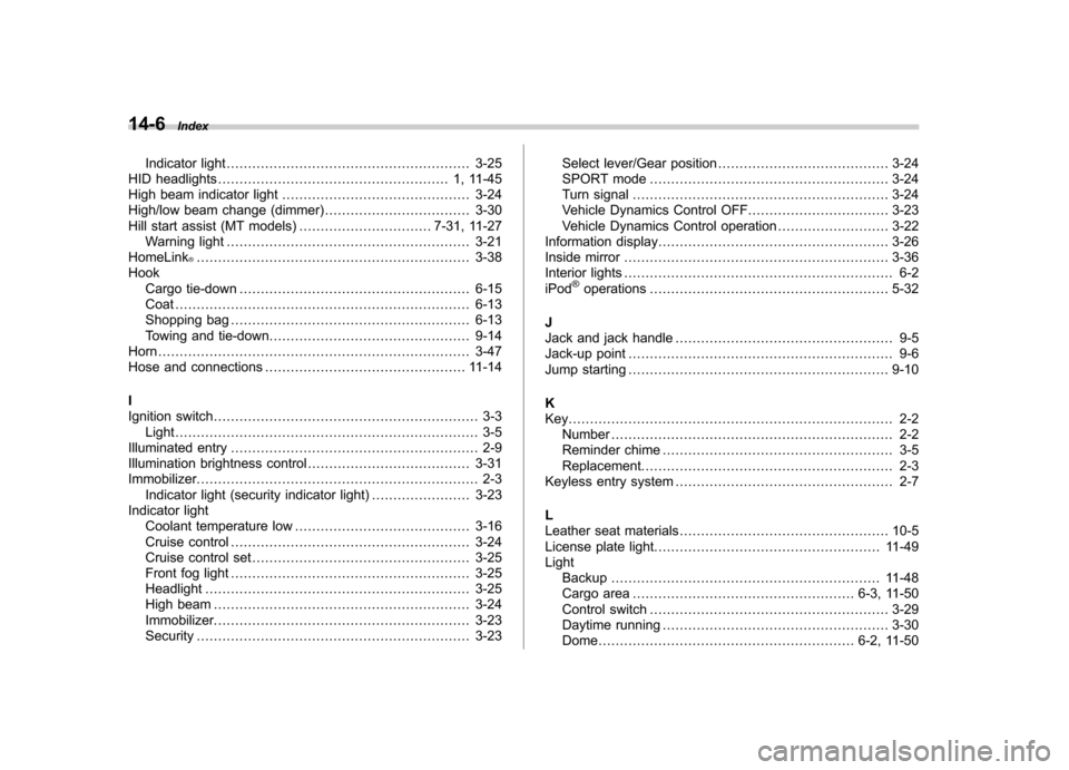
14-6Index
Indicator light ......................................................... 3-25
HID headlights ...................................................... 1, 11-45
High beam indicator light ............................................ 3-24
High/low beam change (dimmer) .................................. 3-30
Hill start assist (MT models) ............................... 7-31, 11-27
Warning light ......................................................... 3-21
HomeLink
®................................................................ 3-38
Hook Cargo tie-down ...................................................... 6-15
Coat ..................................................................... 6-13
Shopping bag ........................................................ 6-13
Towing and tie-down ............................................... 9-14
Horn ......................................................................... 3-47
Hose and connections ............................................... 11-14
I
Ignition switch .............................................................. 3-3
Light ....................................................................... 3-5
Illuminated entry .......................................................... 2-9
Illumination brightness control ...................................... 3-31
Immobilizer. ................................................................. 2-3
Indicator light (security indicator light) ....................... 3-23
Indicator light
Coolant temperature low ......................................... 3-16
Cruise control ........................................................ 3-24
Cruise control set ................................................... 3-25
Front fog light ........................................................ 3-25
Headlight .............................................................. 3-25
High beam ............................................................ 3-24
Immobilizer. ........................................................... 3-23
Security ................................................................ 3-23 Select lever/Gear position
........................................ 3-24
SPORT mode ........................................................ 3-24
Turn signal ............................................................ 3-24
Vehicle Dynamics Control OFF ................................. 3-23
Vehicle Dynamics Control operation .. ........................ 3-22
Information display ...................................................... 3-26
Inside mirror .............................................................. 3-36
Interior lights ............................................................... 6-2
iPod
®operations ........................................................ 5-32
J
Jack and jack handle ................................................... 9-5
Jack-up point .............................................................. 9-6
Jump starting ............................................................. 9-10
K
Key............................................................................ 2-2 Number .................................................................. 2-2
Reminder chime ...................................................... 3-5
Replacement. .......................................................... 2-3
Keyless entry system ................................................... 2-7
L
Leather seat materials ................................................. 10-5
License plate light ..................................................... 11-49
Light Backup ............................................................... 11-48
Cargo area .................................................... 6-3, 11-50
Control switch ........................................................ 3-29
Daytime running ..................................................... 3-30
Dome ............................................................ 6-2, 11-50