2013 SUBARU FORESTER height
[x] Cancel search: heightPage 60 of 436

WARNING
. Put children aged 12 and under in
the rear seat properly restrained
at all times. The SRS airbag
deploys with considerable speed
and force and can injure or even
kill children, especially if they are
12 years of age and under and
are not restrained or improperly
restrained. Because children are
lighter and weaker than adults,
their risk of being injured from
deployment is greater.
For that reason, we strongly
recommend that ALL children
(including those in child seats
and those that have outgrown
child restraint devices) sit in the
REAR seat properly restrained at
all times in a child restraint
device or in a seatbelt, whichever
is appropriate for the child ’s age,
height and weight.
Secure ALL types of child re-
straint devices (including for-
ward facing child seats) in the
REAR seats at all times.
According to accident statistics,
children are safer when properly
restrained in the rear seating positions than in the front seat-
ing positions.
For instructions and precautions
concerning the child restraint
system, refer to
“Child restraint
systems ”F 1-22.
. NEVER INSTALL A REARWARD
FACING CHILD SEAT IN THE
FRONT SEAT. DOING SO RISKS
SERIOUS INJURY OR DEATH TO
THE CHILD BY PLACING THECHILD ’S HEAD TOO CLOSE TO
THE SRS AIRBAG.
. Never allow a child to stand up,
or to kneel on the front passen-ger ’s seat, or never hold a child
on your lap or in your arms. The
SRS airbag deploys with consid-
erable force and can injure or
even kill the child.
CAUTION
. When the SRS airbag deploys,
some smoke will be released.
This smoke could cause breath-
ing problems for people with a
history of asthma or other
breathing trouble. If you or your
passengers have breathing pro-
blems after SRS airbag deploys, get fresh air promptly.
. A deploying SRS airbag releases
hot gas. Occupants could get
burned if they come into direct
contact with the hot gas.
NOTE
When you sell your vehicle, we urge
you to explain to the buyer that it is
equipped with SRS airbags by alerting
the buyer to the applicable section in
this Owner ’s Manual.
Seat, seatbelt and SRS airbags
1-35
– CONTINUED –
Page 142 of 436
&Automatic headlight beam
leveler (models with HID headlights)
The HID headlights generate more light
than conventional halogen headlights.
Therefore a driver of an oncoming vehicle
may experience too much glare if your
headlight beam height adjustment is high
when the vehicle is carrying a heavy load.
The automatic headlight beam leveler
adjusts the headlight beam height auto-
matically and optimally according to the
load being carried by the vehicle.
The automatic headlight beam leveler has
a warning light on the combination meter.
Refer to “Automatic headlight beam leve-
ler warning light (models with HID head-lights) ”F 3-21. Turn signal lever
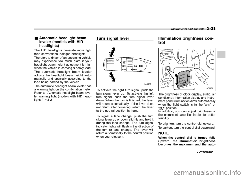
To activate the right turn signal, push the
turn signal lever up. To activate the left
turn signal, push the turn signal lever
down. When the turn is finished, the lever
will return automatically. If the lever does
not return after cornering, return the lever
to the neutral position by hand.
To signal a lane change, push the turn
signal lever up or down slightly and hold it
during the lane change. The turn signal
indicator lights will flash in the direction of
the turn or lane change. The lever will
return automatically to the neutral position
when you release it. Illumination brightness con- trol
The brightness of clock display, audio, air
conditioner, information display and instru-
ment panel illumination dims automatically
when the light switch is in the
“
”or
“” position.
In addition, you can adjust brightness of
the instrument panel illumination for better
visibility.
To brighten, turn the control dial upward.
To darken, turn the control dial downward. NOTE
When the control dial is turned fully
upward, the illumination brightness
becomes the maximum and the auto- Instruments and controls
3-31
– CONTINUED –
Page 308 of 436
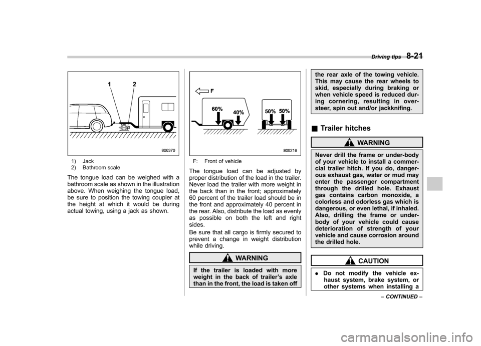
1) Jack
2) Bathroom scale
The tongue load can be weighed with a
bathroom scale as shown in the illustration
above. When weighing the tongue load,
be sure to position the towing coupler at
the height at which it would be during
actual towing, using a jack as shown.F: Front of vehicle
The tongue load can be adjusted by
proper distribution of the load in the trailer.
Never load the trailer with more weight in
the back than in the front; approximately
60 percent of the trailer load should be in
the front and approximately 40 percent in
the rear. Also, distribute the load as evenly
as possible on both the left and rightsides.
Be sure that all cargo is firmly secured to
prevent a change in weight distribution
while driving.
WARNING
If the trailer is loaded with more
weight in the back of trailer ’s axle
than in the front, the load is taken off the rear axle of the towing vehicle.
This may cause the rear wheels to
skid, especially during braking or
when vehicle speed is reduced dur-
ing cornering, resulting in over-
steer, spin out and/or jackknifing.
& Trailer hitches
WARNING
Never drill the frame or under-body
of your vehicle to install a commer-
cial trailer hitch. If you do, danger-
ous exhaust gas, water or mud may
enter the passenger compartment
through the drilled hole. Exhaust
gas contains carbon monoxide, a
colorless and odorless gas which is
dangerous, or even lethal, if inhaled.
Also, drilling the frame or under-
body of your vehicle could cause
deterioration of strength of your
vehicle and cause corrosion around
the drilled hole.
CAUTION
. Do not modify the vehicle ex-
haust system, brake system, or
other systems when installing a Driving tips
8-21
– CONTINUED –
Page 342 of 436
the engine has stopped.
& When checking or servicing
in the engine compartment
while the engine is running
WARNING
A running engine can be dangerous.
Keep your fingers, hands, clothing,
hair and tools away from the cooling
fan, belts and any other moving
engine parts. Removing rings,
watches and ties is advisable. Engine hood
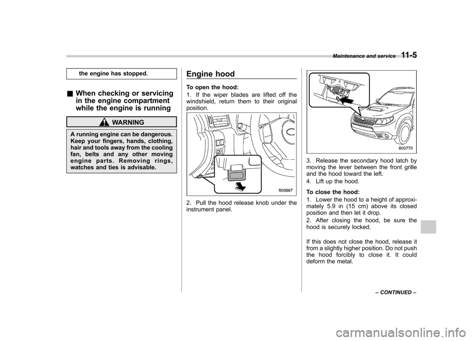
To open the hood:
1. If the wiper blades are lifted off the
windshield, return them to their originalposition.
2. Pull the hood release knob under the
instrument panel.
3. Release the secondary hood latch by
moving the lever between the front grille
and the hood toward the left.
4. Lift up the hood.
To close the hood:
1. Lower the hood to a height of approxi-
mately 5.9 in (15 cm) above its closed
position and then let it drop.
2. After closing the hood, be sure the
hood is securely locked.
If this does not close the hood, release it
from a slightly higher position. Do not push
thehoodforciblytocloseit.Itcould
deform the metal.Maintenance and service
11-5
– CONTINUED –
Page 362 of 436
WARNING
Never let clutch fluid contact your
eyes because clutch fluid can be
harmful to your eyes. If clutch fluid
gets in your eyes, immediately flush
them thoroughly with clean water.
For safety, wearing eye protection isadvisable.
CAUTION
. Clutch fluid absorbs moisture
from the air. Any absorbed moist-
ure can cause improper clutchoperation.
. If the vehicle requires frequent
refilling, there may be a leak. If
you suspect a problem, have the
vehicle checked at your SUBARU
dealer.
. When clutch fluid is added, be
careful not to allow any dirt into
the tank.
. Never splash the clutch fluid over
painted surfaces or rubber parts.
Alcohol contained in the clutch
fluid may damage them.
. Be careful not to spill clutch fluid
when adding it. If clutch fluid
touches the exhaust pipe, it may cause a bad smell, smoke, and/or
a fire. If clutch fluid gets on the
exhaust pipe, be sure to wipe itoff.
& Recommended clutch fluid
Refer to “Fluids ”F 12-9.
CAUTION
Never use different brands of clutch
fluid together. Also, avoid mixing
DOT 3 and DOT 4 brake fluids even if
they are the same brand. Brake booster
If the brake booster does not operate as
described in the following, have it checked
by your SUBARU dealer.
1. With the engine off, depress the brake
pedal several times, applying the same
pedal force each time. The distance the
pedal travels should not vary.
2. With the brake pedal depressed, start
the engine. The pedal should move
slightly down to the floor.
3. With the brake pedal depressed, stop
the engine and keep the pedal depressed
for 30 seconds. The pedal height should
not change.
4. Start the engine again and run for
approximately 1 minute then turn it off.
Depress the brake pedal several times to
check the brake booster. The brake
booster operates properly if the pedal
stroke decreases with each depression. NOTE
For models equipped with the brake
assist system, when you depress the
brake pedal strongly or suddenly while
the engine is running, the following
phenomena occur. They do not indicate
any malfunctions, and the brake assist
system is operating properly.Maintenance and service
11-25
– CONTINUED –
Page 391 of 436
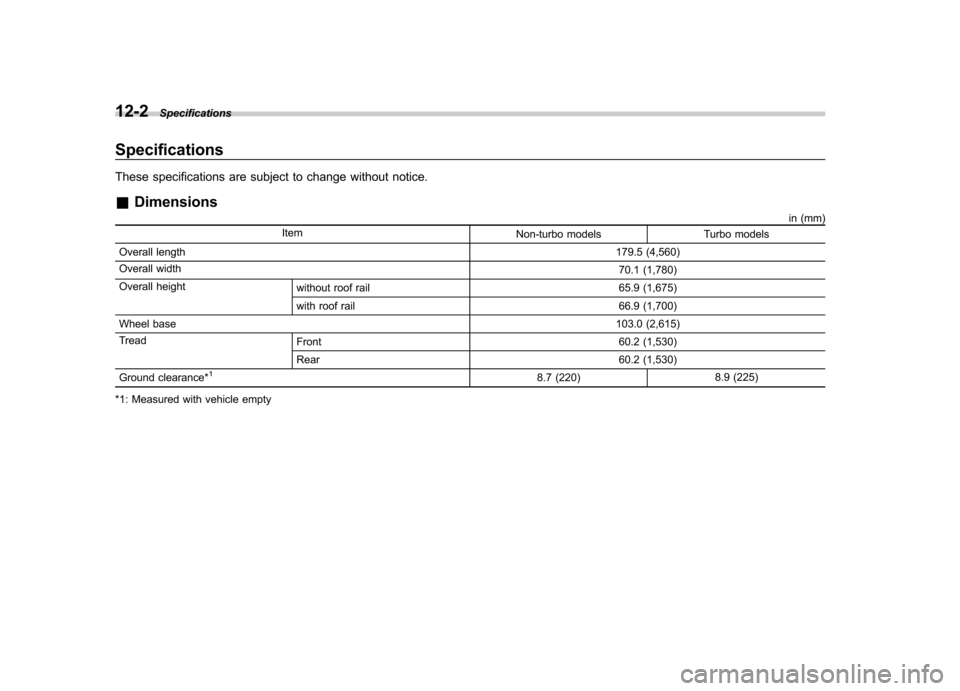
12-2Specifications
Specifications
These specifications are subject to change without notice. &Dimensions
in (mm)
Item Non-turbo models Turbo models
Overall length 179.5 (4,560)
Overall width 70.1 (1,780)
Overall height without roof rail 65.9 (1,675)
with roof rail 66.9 (1,700)
Wheel base 103.0 (2,615)
Tread Front 60.2 (1,530)
Rear 60.2 (1,530)
Ground clearance*
18.7 (220) 8.9 (225)
*1: Measured with vehicle empty
Page 409 of 436
13-2Consumer information and Reporting safety defects
For U.S.A.
The following information has been
compiled according to Code of
Federal Regulations “Title 49, Part
575 ”. Tire information &
Tire labeling
Many markings (e.g. Tire size, Tire
Identification Number or TIN) are
placed on the sidewall of a tire by
tire manufacturers. These markings
can provide you with useful infor-
mation on the tire. ! Tire size
Your vehicle comes equipped with
P-Metric tire size. It is important to
understand the sizing system in
selecting the proper tire for your
vehicles. Here is a brief review of
the tire sizing system with a break-
down of its individual elements. ! P Metric
With the P-Metric system, Section
Width is measured in millimeters.
To convert millimeters into inches,
divide by 25.4. The Aspect Ratio
(Section Height divided by Section
Width) helps provide more dimen-
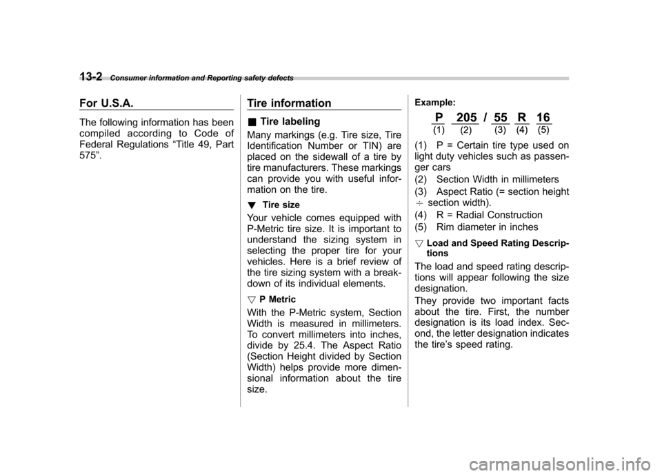
sional information about the tiresize. Example:
(1) P = Certain tire type used on
light duty vehicles such as passen-
ger cars
(2) Section Width in millimeters
(3) Aspect Ratio (= section height 7
section width).
(4) R = Radial Construction
(5) Rim diameter in inches ! Load and Speed Rating Descrip- tions
The load and speed rating descrip-
tions will appear following the size designation.
They provide two important facts
about the tire. First, the number
designation is its load index. Sec-
ond, the letter designation indicates
the tire ’s speed rating.
Page 428 of 436

EngineCompartment overview ........................................... 11-7
Coolant ........................................................ 11-14, 12-9
Exhaust gas (carbon monoxide) ............................. 6, 8-2
Hood .................................................................... 11-5
Oil................................................................ 11-9, 12-5 Overheating .......................................................... 9-13
Starting ................................................................... 7-7
Stopping ................................................................. 7-9
Exterior care .............................................................. 10-2
F
Flat tires ..................................................................... 9-6
Floor mat .................................................................. 6-12
Fluid level Automatic transmission .......................................... 11-20
Brake .................................................................. 11-23
Clutch .................................................................. 11-24
Power steering ..................................................... 11-22
Fog light Bulb ................................................................... 12-15
Indicator light ......................................................... 3-25
Switch .................................................................. 3-32
Folding mirror switch .................................................. 3-44
Front Differential gear oil ........................................ 11-21, 12-8
Fog light ..................................................... 3-32, 12-15
Fog light indicator light ............................................ 3-25
Seatbelt pretensioners ............................................ 1-20
Turn signal light .................................................... 11-48
Front seats .................................................................. 1-2 Forward and backward adjustment
............................ 1-3
Head restraint adjustment ......................................... 1-5
Power seat ............................................................. 1-4
Reclining ................................................................ 1-3
Seat height adjustment (driver ’s seat) ........................ 1-4
Fuel ........................................................................... 7-2
Consumption indicator ............................................. 3-26
Economy hints ........................................................ 8-2
Filler lid and cap ...................................................... 7-3
Gauge ................................................................... 3-10
Requirements ................................................. 7-2, 12-4
Fuses ..................................................................... 11-44
Fuses and circuits .................................................... 12-11
G
GAWR (Gross Axle Weight Rating) .. ............................. 8-13
Glove box ................................................................... 6-5
GVWR (Gross Vehicle Weight Rating) ........................... 8-13
H
Hands-free system. ..................................................... 5-42
Hazard warning flasher .......................................... 3-5, 9-2
Head restraint adjustment Front seat ............................................................... 1-5
Rear seat ............................................................... 1-8
Headlight
Beam leveler. ......................................................... 3-31
Bulb replacing ...................................................... 11-45
Bulb wattage ........................................................ 12-15
Control switch ........................................................ 3-29
Flasher .................................................................. 3-30 Index
14-5