Page 201 of 796

02-42
(3) Functions
Piston transfers the combustion energy from engine to connecting rod. Especially in the direct injection
engine such as D20DTF, it provides the combustion space and largely effects to the engine performance
and exhaust gas.
Piston ring
#1 ring (Top ring) : Prevents the high pressurized combustion gas from leaking into crank chamber,
and prevents the engine oil getting into combustion chamber.
#2 ring: Scrapes the engine oil on the cylinder bore, and prevents the leaked combustion gas from #1
ring from leaking into the crank chamber.
Oil ring: Scrapes the engine oil on the cylinder bore.
Piston pin
Connects the piston the connecting rod, and transfers the linear movement of piston to connecting
rod to convert it to rotating energy
Snap pin
Locks the piston pin. ▶
-
-
-
▶
-
▶
-
(4) Assembling the piston
Install the piston rings with the "Y" mark on
the ring facing upwards.
Position the end gap of #1 ring at 180˚
away from the end gap of #1 ring.
Position the end gap of oil ring at 180˚
away from the end gap of coil spring, and
position the end gap of oil ring at 90˚
away from the end gap of #2 ring. 1.
2.
3.
Page 202 of 796
02-430000-00
Selecting piston oversize
Top of piston Top of cylinder block
EnginePiston Cylinder bore
Part NO Marking NO.-
D20DTF 671 030 06 17 - -
671 037 07 01 A A
671 037 08 01 X X
671 037 09 01 B B
671 037 10 01 +5 -
671 037 11 01 +10 -
Page 207 of 796
02-48
4) Cylinder Block
(1) Overview
The major dimensions in D20DTR are similar to
D20DTR engine. It has two mounting
bosses for knock sensor and meets the
requirements for EURO5 regulation.
(2) Layout
Right sideCylindrical pin
Expansion plug
Screw plug
Page 209 of 796
02-50
The bottom side of water jacket is desgined as sine wave to strengthen the structure of crankcase. The
main flow of coolant starts from outlet port of water pump and goes along the longitudinal direction of
engine. The coolant passage from cylinder head to inlet port of water pump is integrated in cylinder
head.
The engine oil from oil pump is supplied to the main oil gallery through oil channel, oil filter module and
cross bore in cylinder block without using external pipes. This oil is supplied to main bearing, cylinder
head and MBU. And, it is sprayed to the chain through the chain tensioner connected to cross bore.
Crankcase cross bore for oil supply
Water jacket core
Page 210 of 796
03-32210-01
1. SPECIFICATIONS
Description Specification
Fuel Diesel
Fuel filter Type Fuel heater + priming pump + water
separator integrated type
Filter type Changeable filter element type
Change interval EU every 40,000 km
GEN every 45,000 km
Water separation
intervalEU every 20,000 km
GEN every 15,000 km
Water accumulating capacity 200 cc
Heater capacity 250W 13.5V
Injector System pressure 1800 bar
High pressure fuel
pumpType Eccentric cam/Plunger type
Operating type Gear driven type
Normal operating temperature-40 ~ 125˚C
Operating pressure 1800 bar
Operating temperature-30 ~ 120˚C
Low pressure fuel
pumpType Vane type
Gear ratio (pump/engine) 0.5 : 1
Pressure 6 bar
Fuel tank Capacity 80 L
Material Plastic
Fuel sender Single sender type
Page 211 of 796
03-4
Took kit for low pressure lineTool kit for high pressure line
2. MAINTENANCE AND INSPECTION
1) Maintenance Procedures for DI Engine Fuel System
Always keep the workshop and lift clean (especially, from dust).
Always keep the tools clean (from oil or foreign materials).
Wear a clean vinyl apron to prevent the fuzz, dust and foreign materials from getting into fuel
system. Wash your hands and do not wear working gloves. 1.
2.
3.
Follow the below procedures before starting service works for fuel system.
If the problem is from HP pump, fuel supply line or injector, prepare the clean special tools and
sealing caps to perform the diagnosis for DI engine fuel system in this manual. At this point,
thoroughly clean the related area in engine compartment. 4.
Clean the engine compartment before starting service works.
Page 212 of 796

03-52210-01
Plug the removed components with clean and undamaged sealing caps and store it into the box to
keep the conditions when it was installed. 6.
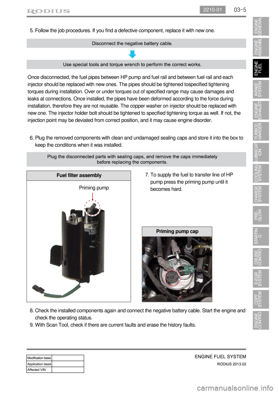
Fuel filter assembly
Follow the job procedures. If you find a defective component, replace it with new one. 5.
Once disconnected, the fuel pipes between HP pump and fuel rail and between fuel rail and each
injector should be replaced with new ones. The pipes should be tightened tospecified tightening
torques during installation. Over or under torques out of specified range may cause damages and
leaks at connections. Once installed, the pipes have been deformed according to the force during
installation, therefore they are not reusable. The copper washer on injector should be replaced with
new one. The injector holder bolt should be tightened to specified tightening torque as well. If not, the
injection point may be deviated from correct position, and it may cause engine disorder.
To supply the fuel to transfer line of HP
pump press the priming pump until it
becomes hard. 7.
Priming pump
Check the installed components again and connect the negative battery cable. Start the engine and
check the operating status.
With Scan Tool, check if there are current faults and erase the history faults. 8.
9.
Priming pump cap
Page 213 of 796
03-6
2) Diagnostic Test for Engine Fuel System
(1) Overview
If a DTC is displayed on the diagnostic device, check the low pressure- and high pressure fuel
systems before removing the components.
To run the system properly, the electric system must be intact but for the DI engine, the fuel pressure
should be measured also when there is a malfunction even after the diagnostic test with a diagnostic
device.
(2) Hydraulic system